ISSN: 2615-9740
JOURNAL OF TECHNICAL EDUCATION SCIENCE
Ho Chi Minh City University of Technology and Education
Website: https://jte.edu.vn
Email: jte@hcmute.edu.vn
JTE, Volume 19, Issue 06, 2024
45
The Controller Improves Voltage Quality In Microgrids
Xuan Hoa Thi Pham , Hien-Thanh Le*
Ho Chi Minh City University of Industry and Trade, Vietnam
*Corresponding author. Email: hienlt@huit.edu.vn
ARTICLE INFO
ABSTRACT
24/05/2024
The inverters in the microgrid are connected in parallel to improve efficiency.
When the Microgrid is operating in standalone mode, the inverters must be
controlled to share their power to stabilize the frequency and voltage. The
droop control method is one of the most popular power-sharing methods
today, some studies have presented traditional and improved droop control
methods. However, the purpose of the studies is power-sharing for the
inverters that no purpose of reducing the voltage and frequency deviation to
improve power quality. This paper presents a voltage and frequency
adjustment method based on fuzzy logic to minimize voltage and frequency
deviation to improve power quality in microgrids. This controller includes a
Droop controller combined with fuzzy logic, the fuzzy logic block will
control to change in the slope of the Droop characteristic curve when the load
changes. The purpose of the proposed method is to improve the accuracy of
power-sharing for inverters and at the same time minimize voltage and
frequency deviations in microgrids. Simulation results will prove the
effectiveness of the proposed method.
20/09/2024
07/10/2024
28/12/2024
KEYWORDS
Power sharing;
Microgrid control;
Parallel inverter;
Fuzzy logic;
Non-linear load.
Doi: https://doi.org/10.54644/jte.2024.1602
Copyright © JTE. This is an open access article distributed under the terms and conditions of the Creative Commons Attribution-NonCommercial 4.0
International License which permits unrestricted use, distribution, and reproduction in any medium for non-commercial purpose, provided the original work is
properly cited.
1. Introduction
The microgrid includes a system of distributed generation (DG) sources, which uses renewable
energy sources such as solar energy, wind energy and storage. However, in stand-alone mode, the
microgrid must have power sh`aring between inverters connected in parallel to maintain voltage and
frequency stability.
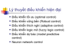
Fig. 1. The microgrid consists of several inverters connected in parallel coupling (PCC)
Bus DC
Line
impedance 1
Inverter 1
Bus DC
Line
impedance 2
Inverter 2
Bus DC
Line
impedance n
Inverter n
Point of Common
Coupling (PCC)
ISSN: 2615-9740
JOURNAL OF TECHNICAL EDUCATION SCIENCE
Ho Chi Minh City University of Technology and Education
Website: https://jte.edu.vn
Email: jte@hcmute.edu.vn
JTE, Volume 19, Issue 06, 2024
46
If there is no power sharing between inverters, there will be a balanced current flowing between the
inverters, which can cause overload or even damage the inverter [1-3]. Based on the power
characteristics of the source, previous studies have established a mathematical model for the droop
controller to control the power-sharing between inverters operating in parallel. The droop controller
controls active power according to frequency and controls reactive power according to voltage.
Relationship between active power and frequency; Reactive power and voltage are expressed through
slope coefficients [1-5]. Therefore, researchers relied on the slope factor to realize power sharing
between parallel-connected inverters. Several studies have presented traditional droop control methods
for power sharing. The purpose of this study is to share power among inverters without aiming to reduce
voltage and frequency deviation to improve power quality. However, the traditional droop controller is
affected by the line impedance parameter. Therefore, there have been several studies presenting
improved droop control methods for power sharing [5-8]. However, the purpose of these studies is to
improve the accuracy of power-sharing for inverters without aiming to reduce voltage and frequency
deviations to improve power quality.
Therefore, this paper designs a droop controller combined with fuzzy logic to overcome the
disadvantages of previous controllers. The purpose of these studies is to improve the accuracy of power-
sharing for inverters without aiming to reduce voltage and frequency deviations to improve power
quality. The droop-fuzzy logic controller automatically adjusts the slope of the droop characteristic
curves when the load changes. Therefore, this controller will minimize the frequency and voltage
deviation, it improves power quality in microgrid. In addition, the droop-fuzzy logic controller correctly
power-sharing between the parallel-connected inverters in the Microgrid. Typically, the structure of an
island microgrid consisting of inverters operating in parallel is shown in Figure 1. In standalone mode,
the microgrid must be capable of self-stabilizing voltage and the frequency.
2. Proposed controller
Fig. 2. Block diagram of the proposed controller for an inverter in islanded microgrid
The model of the proposed controller is shown in Figure 2. The proposed control system includes
the following blocks: the external controller is the Droop- fuzzy logic power controller to control the
power-sharing for the inverters, and the inside controllers are current and voltage controllers to control
the current and voltage at the output of the inverter.
ISSN: 2615-9740
JOURNAL OF TECHNICAL EDUCATION SCIENCE
Ho Chi Minh City University of Technology and Education
Website: https://jte.edu.vn
Email: jte@hcmute.edu.vn
JTE, Volume 19, Issue 06, 2024
47
2.1. Design of the droop controller
Fig. 3. Equivalent schematic of inverters connected to a load
According to Fig 3, the active and reactive power supplied by the inverter are calculated as follows
[9-12]:
P= V
R2+X2[R(V-VPCCcosδ)+XVPCCsinδ]
Q= V
R2+X2[-RVPCCsinδ+X(V-VPCCcosδ)]
(1)
(2)
When the angle is small and X>>R, equations (1) and (2) are rewritten as shown as formula (3),
(4):
δXP
VVPCC
(3)
V-VPCCXQ
V
(4)
Expressions (3) and (4) show that the frequency depends on the active power (P), and the voltage
deviation depends on the reactive power (Q). From the expressions (3) and (4), we can conclude that the
voltage is controlled by Q, and the frequency is controlled by P. Therefore, the droop characteristics P/f
and Q/V are used according to expressions (5) and (6), presented as shown in Figure 4:
f=f0-mp(P-P0)
(5)
V=V0-mq(Q-Q0)
(6)
Where: V0 and f0 are the nominal amplitude voltage and the nominal frequency of the inverter; V and
are the measured amplitude voltage and the measured frequency of the inverter; P and Q are the active
power and reactive power at output of the inverter; mp and mq are the slope coefficients, which are
calculated as follows formula (7):
mp=f0-fmin
Pmax-P0
; mq=V0-Vmin
Qmax-Q0
(7)
2.2. Design of the fuzzy logic controller
Equations (5) and (6) show that: V=V0 and f=f0 can only be obtained when Q=Q0 and P=P0.
When the active power of the load increases then the frequency decreases and when the active
power of the load decreases then the frequency increases. When the reactive power of the load
increases, then the voltage decreases and when the reactive power of the load decreases, then
the voltage increases. That means, when the reactive power of the load changes by an amount
∆Q, it will cause a corresponding voltage deviation ∆V; When the active power of the load
changes by an amount ∆P, it will cause a corresponding frequency deviation ∆f.
ISSN: 2615-9740
JOURNAL OF TECHNICAL EDUCATION SCIENCE
Ho Chi Minh City University of Technology and Education
Website: https://jte.edu.vn
Email: jte@hcmute.edu.vn
JTE, Volume 19, Issue 06, 2024
48
(a)
(b)
Fig. 4. (a) The droop P/f characteristic; (b) The droop Q/V characteristic
The equations (5) and (6) show that the power-sharing for inverters depends on the slope coefficients
determined in equation (7). Figure 4 shows that the frequency at the output of the inverter changes
according to the active power of the load and the voltage at the output of the inverter changes according
to the reactive power of the load; The graph of droop P/f and Q/V in (5) and (6) have slopes that depend
on (7). When the slopes (7) change, the power sharing will change accordingly.
Fig. 5. The proposed Droop-fuzzy logic controller
Therefore, this paper proposes a method to shift the slope coefficients mp and mq according to
changes in the load instead of fixing them according to the equation (7). In the conventional droop
method, the slope coefficients mp and mq are fixed according to equation (7). When the load increases
or decreases sharply, the frequency and voltage at the output of the inverter will deviate much from the
value of its norm. The block diagram for the proposed droop-fuzzy logic controller is shown in Figure
5. Figure 5 is combined from equations (5), (6) and fuzzy-logic block to adjust the slope coefficients mp
and mq.
a. The input signal of fuzzy logic controller:
The input signal of fuzzy logic controller Q/V:
The first input signal is eq = Q Q0
(8)
The second input signal is the rate of change of Q over time as dQ
dt
(9)
The input signal of fuzzy logic controller P/f:
The first input signal is ep = P P0
(10)
The second input signal is the rate of change of P over time as dP
dt
(11)
ISSN: 2615-9740
JOURNAL OF TECHNICAL EDUCATION SCIENCE
Ho Chi Minh City University of Technology and Education
Website: https://jte.edu.vn
Email: jte@hcmute.edu.vn
JTE, Volume 19, Issue 06, 2024
49
b. The output signal of fuzzy logic controller:
The output signal of fuzzy logic controller Q/V:
The output signal of fuzzy logic controller Q/V is the slope 𝑚𝑞
The output signal of fuzzy logic controller P/f:
The output signal of fuzzy logic controller P/f is the slope 𝑚𝑝
c. Define language variables for input and output:
Select 5 language variables for first input signal as shown in formula (12)
ep = eq = {NB, NS, ZE, PS, PB}
(12)
NB: more negative; NS: less negative; ZE: equal zero; PS: less positive; PB: much positive
Select 3 language variables for second input signal: dQ
dt =dP
dt ={N,Z,P}
(13)
N: negative; Z: zero; P: positive
Select 9 language variables for output signal as shown in formula (14)
mp= mq= {A1, A2, A3; B1, B2, B3; C1, C2, C3}
(14)
A1, A2, A3: small; B1, B2, B3: medium; C1, C2, C3: big
d. Select value domain for input and output:
Based on equations (10), (11), (14) and values P, Q, P0, Q0, we choose the range of values for the
inputs and outputs:
The value domain for the first input: ep = [-3500; 3500], eq = [-500; 500]
The value domain for the second input: 𝑑𝑃
𝑑𝑡 = [−100; 100], 𝑑𝑄
𝑑𝑡 = [−50; 50]
The value domain for the output: mp = mq = [0;5. e-4]
e. Define membership functions for input and output:
(a)
(b)
(c)
(d)
NB NS ZE PS PB
-3500 0
-1750 1750 3500
(ep) m
(ep)
NB NS ZE PS PB
-50 0
-25 25 50
(eq) m
(eq)
dQ/dt
m
N Z P
-50 -25 25 50
(dQ/dt)
dP/dt
m
N Z P
-100 -50 50 100
(dP/dt)