
25
Journal of Science, Technology and Engineering Mien Tay Construction University (ISSN: 3030-4806) No.14 (09/2025)
The Design of the Vertical Sand Drain
Le T. B. T.1,*
1Department of Civil Engineering, National Central University, No.300, Zhongda Rd.,
Zhongli District, Taoyuan City, Taiwan 320317 (R.O.C.)
*Corresponding author: 112382603@cc.ncu.edu.tw
■ Received: 03/03/2025 ■ Revised: 27/03/2025 ■ Accepted: 13/06/2025
ABSTRACT
A vertical sand drain is designed to allow fluids to drain from clay or silty soil by drilling a hole
and filling it with sand or gravel. Sand drains are required for building in places where drainage
is limited due to extremely fine soils, such as clay or silt. Therefore, when assessing design
assumptions and construction costs to determine whether sand drain stabilization is feasible for
a particular project, the impact of the sand drain installation method on the in situ characteristics
of the subsoil being treated is crucial. It is the purpose of this paper to review the design of sand
drain installations for use in foundation stabilization with or without using sand drain piles. The
results show that untreated soil consolidates slowly in two cases (H = 6m and 12m), especially
for deeper layers, requiring nearly 1000 days to reach approximately 60% consolidation while
sand drain treatment dramatically reduces consolidation time; in the treated case with SD = 1.5m
achieves near-complete consolidation within approximately 100 days, and another case reaches
similar consolidation levels within approximately 200 days with SD = 2m. The findings suggest that
reducing sand drain spacing and employing sand drain treatment effectively reduce consolidation
time, which is essential for construction projects involving soft soil layers.
Keywords: vertical sand drain, soft soil, construction, stabilization, consolidation
INTRODUCTION
A strategy or approach used to improve
land that is in poor condition or in a disturbed
state is called soil improvement. To improve
the properties of the current soil, it is re-
engineered using a variety of geotechnical
techniques. In order to satisfy the specifications
of the kind of construction that will be built on
that specific plot of land, soil improvement is
typically carried out.
In addition to improving weak soils,
ground improvement techniques also improve
inappropriate and contaminated soils. One
advantage of soil improvement is that it takes
less time because it is relatively quick to
plan and implement. Additionally, when the
procedures are used for ground improvement,
very little waste is produced. Thus, it involves
no disposal expenses; the substructure is simple
to design and build, and ground improvement
works well on a variety of soil types.
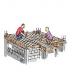
Figure 1. Soil Improvement in the Construction
Industry [1]
There are numerous options for soil
improvement. However, each technique
has unique advantages and disadvantages
in terms of time, performance, and cost.
Soil improvement procedures include pre-
compaction, sand drains, wick drains, stone
columns, deep mixing, and grouting. The
primary purpose of most soil improvement
measures for decreasing liquefaction dangers
is to prevent significant increases in pore water

26
Journal of Science, Technology and Engineering Mien Tay Construction University (ISSN: 3030-4806) No.14 (09/2025)
pressure during earthquake shaking. This can
be accomplished by densifying the soil and
increasing its drainage capacity. This study
will focus on vertical sand drain systems for
pre-loading and hence pre-consolidating soils
before building begins. The goal is to ensure
that all settlement takes place before or during
construction, not after.
2. METHOD
2.1. An overview about the vertical sand
drain pile
Liquefaction concerns can be avoided by
improving soil drainage. If porewater within
the soil can freely drain, surplus pore water
pressure will be decreased. Vertical drains are
commonly used to consolidate soft clay, silt,
and compressible materials. They consist of a
succession of vertical sand drains or piles.
Medium to coarse sand is typically used.
The drains have a diameter of at least 30cm
and are arranged in a square grid pattern at 2
to 3 meter intervals. Economy necessitates a
thorough examination of the influence of sand
drain spacing on consolidation rate.
Figure 2. Schematic figure illustrates the
sand drains [2]
- Vertical drain depth should be equal to
the thickness of the compressible layer.
- A horizontal blanket of free draining
sand should be laid on top of the stratum,
which can be as thick as a meter.
- An embankment is gradually built on top
of the sand blanket to provide a soil surcharge.
2.2. Design the vertical sand drain pile
Design the vertical sand drain pile [3]:
Step 1. Using a specified time, t and
coefficient of consolidation, Cv, and the
drainage path without sand drains, calculate
the time factors, Tv; v
v2
Ct
T=
H
Step 2. Use the theoretical time factor, Tv,
to find the corresponding Uv. This gives the
degree of consolidation that can be obtained
without the use of radial drains.
Step 3. If Uv is less than the required
degree of consolidation, then calculate the
required Uh;
h
h
v
1-U
U =1-1-U
.
Step 4. Choose a specific well-drain
diameter, dw and solve for the effective radial
drainage, R, where, R = nrw; n = constant and
rw = radius of well.
2.3. Install the vertical sand drain piles
Sand drains are built by drilling holes
through the clay layer with rotary drills,
continuous flight augers, or by pushing
hollow mandrels into the soil. The holes
are subsequently filled with sand. When a
surcharge is applied to the ground surface, the
pressure of pore water in the clay increases,
which is then dissipated via draining in the
horizontal as well as vertical directions. As
a result, the settlement process is hastened
(Fig.2).
Sand drains can be used to form sand
piles. They help to reinforce the soft ground
in which they are placed. Even hif sand drains
substitute only 1 to 2% of the soil volume,
the total increase in bearing capacity could be
more than 10% [4].
However, they do have certain
disadvantages [5, 6]:
• Installing sand drains by driving hollow
mandrels disturbs the soil around each drain.
This may decrease the amount of water into
the drain.
• During the filling, sand bulking may
occur, resulting in voids.

27
Journal of Science, Technology and Engineering Mien Tay Construction University (ISSN: 3030-4806) No.14 (09/2025)
• The huge dimension of sand drains may
cause construction and/or budgetary issues.
2.4. Patterns of vertical sand drain piles
There are several common patterns of
vertical sand drain columns used in ground
improvement techniques, each with different
efficiency levels in terms of soil consolidation
and drainage performance. Here are the most
widely used patterns:
Figure 3. Installation of sand drain piles [7]
2.4.1. Rectangular Pattern
Similar to the square pattern but with
different spacing in one direction (longer in
one axis).
Spacing: The horizontal distance x differs
from the vertical distance y.
Advantages: Suitable for sites where
one direction of drainage needs to be more
effective.
Disadvantages: May lead to uneven
consolidation rates if spacing is too irregular.
2.4.2. Square Pattern
Sand drains are arranged in a grid-like
square pattern.
Spacing: Equal distance d between
adjacent drains in both horizontal and vertical
directions.
Advantages:
Simple and easy to implement.
Works well for uniform soil conditions.
Disadvantages: Less efficient than
triangular patterns in terms of reducing
drainage distance
2.4.3. Consolidation due to sand drains
The diagram on the right shows the radial
consolidation effect around a sand drain.
The drainage path is influenced by the
cylindrical influence zone around each sand
drain.
The effective drainage diameter (dc = 2re)
represents the area of influence for each sand
drain.
Water within the clay layer is forced
to move towards the sand drains due to the
applied load, reducing pore water pressure
and increasing consolidation rate.
The consolidation process is depicted with
the movement of water towards the sand drain,
leading to a decrease in settlement over time.
3. CALCULATION CASE OF THE
VERTICAL SAND DRAIN PILES
Suppose the thickness of two soft layers
are 6 and 12m, and each layer is divided into

28
Journal of Science, Technology and Engineering Mien Tay Construction University (ISSN: 3030-4806) No.14 (09/2025)
untreated area and sand pile treated area.
40-cm-diameter sand piles are set in the treated
area with pitches of 1.5m and 2.0m and the
piles are arranged in the equilateral triangle
shape. Try to find and draw the consolidation
curves of the above conditions. The coefficient
of consolidation is:
cv = cvh = 4.5x10⁻² cm2/min = 6.48x10⁻³ m2/day
(1) Calculation without sand drain piles:
Based on Table of variation of Tv with U,
it can be performed at the below table 1:
Table 1: Variation of Tv with U
U(%) TvU(%) Tv
0 0 50 0.197
5 0.00196 55 0.239
10 0.00785 60 0.286
15 0.0177 65 0.304
20 0.0314 70 0.403
25 0.0491 75 0.477
30 0.0707 80 0.567
35 0.0962 85 0.684
40 0.126 90 0.848
45 0.159 95 1.129
Time of consolidation can be calculated
using this formula:
2
dr v
v
H .T
t= C
Where Cv = C
vh = 4.5x10⁻² cm2/min =
6.48x10⁻³ m2/day
Time of consolidation can be computed in
Table 2.
Table 2: Time of consolidation of
untreated soil
U(%) Tv
Time (day)
H = 6m H = 12m
0000
5 0.00196 11 44
10 0.00785 44 174
15 0.0177 98 393
20 0.0314 174 698
25 0.0491 273 1091
U(%) Tv
Time (day)
H = 6m H = 12m
30 0.0707 393 1571
35 0.0962 534 2138
40 0.126 700 2800
45 0.159 883 3533
50 0.197 1094 4378
55 0.239 1328 5311
60 0.286 1589 6356
65 0.304 1689 6756
70 0.403 2239 8956
75 0.477 2650 10600
80 0.567 3150 12600
85 0.684 3800 15200
90 0.848 4711 18844
95 1.129 6272 25089
(2) Calculation with sand drain piles:
Diameter of sand piles (dw) = 40cm
Pitches = 1.5m and 2.0m
Patterns of piles = the equilateral triangle
shape
We have installation of sand drain piles
are the equilateral triangle arrangement, the
diameter of effective circle (the area controlled
by one sand pile) is: de = 1.05d
Where: d = the pitch of sand piles.
We need to find the relative between Uh
and Th of ground after installation of sand
drain piles.
Figure 4. Relationship of Uh and Th [7]
The diameter of effective circle:

29
Journal of Science, Technology and Engineering Mien Tay Construction University (ISSN: 3030-4806) No.14 (09/2025)
For pitches of 1.5m:
de = 1.05 x 1.5 = 1.575 (m)
For pitches of 2.0m:
de = 1.05 x 2.0 = 2.1 (m)
The coefficient of consolidation:
Cv = Cvh = 4.5x10⁻² cm2/min = 6.48x10⁻³ m2/day
The values of n in the Fig. 4, dw = 0.4m:
For pitches of 1.5m, de = 1.575m:
e
w
d1.575
n = = = 3.9375 4.0
d 0.4 ≈
For pitches of 2.0m, de = 2.1m:
e
w
d2.1
n = = = 5.25 5.3
d 0.4 ≈
Table 3: Calculation of treated soil using
sand drain piles
Using:
2
eh
vh
d .T
t= C
Where: de = 1.575m and de = 2.1m
U
(%)
Coefficient of
consolidation (Th)Time (day)
SD =
1.575m
(n = 4.0)
SD =
2.1m
(n = 5.3)
SD =
1.575m
(n = 4.0)
SD =
2.1m
(n = 5.3)
0 0 0 0 0
5 0.0023 0.0021 1 1
U
(%)
Coefficient of
consolidation (Th)Time (day)
SD =
1.575m
(n = 4.0)
SD =
2.1m
(n = 5.3)
SD =
1.575m
(n = 4.0)
SD =
2.1m
(n = 5.3)
10 0.005 0.0072 2 5
15 0.011 0.017 4 12
20 0.018 0.023 7 16
25 0.022 0.035 8 24
30 0.028 0.042 11 29
35 0.037 0.053 14 36
40 0.044 0.061 17 42
45 0.056 0.074 21 50
50 0.065 0.085 25 58
55 0.078 0.097 30 66
60 0.085 0.129 33 88
65 0.092 0.148 35 101
70 0.119 0.167 46 114
75 0.142 0.178 54 121
80 0.175 0.22 67 150
85 0.19 0.26 73 177
90 0.24 0.32 92 218
95 0.33 0.42 126 286
From results of calculations, it can be
shown below (Fig. 5):
Figure 5. Consolidation time of untreated soil and treated soil using sand drain piles


![Bài giảng Phương pháp luận thiết kế kiến trúc: Chuyên đề 6 - TS. KTS. Khuất Tân Hưng [Mới Nhất]](https://cdn.tailieu.vn/images/document/thumbnail/2025/20251212/tambang1205/135x160/18291768806312.jpg)

![Bài giảng Phương pháp luận thiết kế kiến trúc: Chuyên đề 4 - TS. KTS. Khuất Tân Hưng [Mới nhất]](https://cdn.tailieu.vn/images/document/thumbnail/2025/20251212/tambang1205/135x160/93361768806314.jpg)


![Ứng dụng ChatGPT trong xây dựng công trình ngầm [mới nhất]](https://cdn.tailieu.vn/images/document/thumbnail/2025/20251019/vitobirama/135x160/49571768792813.jpg)


