
TOYOTA TUNDRA – NEW FEATURES
12CEG01Y
12CEG02Y
13
NEW FEATURES
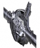
J1UR-FE ENGINE
1. Description
The 1UR-FE engine is a 4.6-liter, 32-valve DOHC V8. This engine uses the Dual Variable Valve
Timing-intelligent (Dual VVT-i) system, Direct Ignition System (DIS), Acoustic Control Induction System
(ACIS), Electronic Throttle Control System-intelligent (ETCS-i), air injection system and Exhaust Gas
Recirculation (EGR) control. These control functions achieve improved engine performance, fuel economy,
and clean emissions.

TOYOTA TUNDRA – NEW FEATURES
14
" Engine Specifications A
No. of Cyls. & Arrangement 8-cylinder, V Type
Valve Mechanism 32-valve DOHC, Chain Drive (with Dual VVT-i)
Combustion Chamber Pentroof Type
Manifolds Cross-flow
Fuel System SFI
Ignition System DIS
Displacement cm3 (cu. in.) 4608 (281.2)
Bore × Stroke mm (in.) 94.0 × 83.0 (3.70 × 3.27)
Compression Ratio 10.2 : 1
Max. Output (SAE-NET)*1231 kW @ 5600 rpm (310 HP @ 5600 rpm)
Max. Torque (SAE-NET)*1443 N⋅m @ 3400 rpm (327 ft⋅lbf @ 3400 rpm)
Valve Timing
Intake Open –18_ to 22_ BTDC
Closed 70_ to 30_ ABDC
Exhaust Open 62_ to 30_ BBDC
Closed – 8_ to 24_ ATDC
Firing Order 1 – 8 – 7 – 3 – 6 – 5 – 4 – 2
Octane Rating 87 or higher
Research Octane Number (RON) 91 or higher
Tailpipe Emission Regulation LEVII-ULEV, SFTP
Evaporative Emission Regulation LEVII, ORVR
Engine Service Mass*2 (Reference) kg (lb) 216.1 (476.5)
*1: Maximum output and torque ratings are determined by revised SAE J1349 standard.
*2: The figure shown is the weight of the part without coolant and oil.

TOYOTA TUNDRA – NEW FEATURES
12CEG03Y
: Intake valve opening angle
: Exhaust valve opening angle
Intake VVT-i
Operation Range
Exhaust VVT-i
Operation Range
TDC
22_8_18_24_
70_
Intake VVT-i
Operation Range 30_
BDC
30_
62_
Exhaust VVT-i
Operation Range
12CEG53Y
460 340
440 320
420 300
400
380 280
360 260
340 240
320
Torque
N⋅m (ft⋅lbf)
320 240
300 220
280 200
260
180
240
160
220
200
140
180
160
120
100
140
120
80
100
80
60
40
60
40
20 20
00
Output
(HP) kW
1000 2000 3000 4000 5000 6000
Engine Speed (rpm)
15
" Valve Timing A
" Performance Curve A

TOYOTA TUNDRA – NEW FEATURES
16
2. Features of 1UR-FE Engine
The 1UR-FE engine has achieved the following performance through the use of the items listed below:
(1) High performance and reliability
(2) Low noise and vibration
(3) Lightweight and compact design
(4) Good serviceability
(5) Clean emission and fuel economy
Item (1) (2) (3) (4) (5)
Engine Proper
A taper squish shape is used for the combustion chamber. f f
An aluminum alloy cylinder block containing an engine
coolant distribution pathway is used. f f
Spiny-type liners are used in the cylinder bores. f f
Cylinder block water jacket spacers are used. f
The piston skirt is coated with resin. f f f
A No. 1 oil pan made of aluminum alloy is used. f f f
Valve
Mechanism
Timing chains and chain tensioners are used. f f
Hydraulic lash adjusters are used. f f f f
Roller rocker arms are used. f f
Lubrication
System
An oil filter with a replaceable element is used. f
A water-cooled type oil cooler is used.* f
Intake and
Exhaust System
A carbon filter is used in the air cleaner cap. f
A linkless-type throttle body is used. f f
An intake manifold made of plastic is used. f f
A step motor type EGR valve is used. f
A water-cooled type EGR cooler is used. f
Stainless steel exhaust manifolds are used. fff
Ceramic type Three-Way Catalytic converters (TWCs)
are used. f
Fuel System 12-hole type fuel injectors are used to improve the
atomization of fuel. f f
Ignition System
The Direct Ignition System (DIS) makes ignition timing
adjustment unnecessary. f f f
Long-reach type iridium-tipped spark plugs are used. f f f
(Continued)
*: Models with towing package

TOYOTA TUNDRA – NEW FEATURES 17
Item (1) (2) (3) (4) (5)
Charging
System A segment conductor type generator is used. f f
Starting System A planetary reduction type starter is used. f
Serpentine Belt
Drive System A serpentine belt drive system is used. f f
Blowby Gas
Ventilation
System
A separator case is provided between the cylinder block
and the intake manifold. f f
Engine Control
System
An magnetic Resistance Element (MRE) type crankshaft
position, a camshaft position, and VVT sensors are used. f
The Electronic Throttle Control System-intelligent
(ETCS-i) is used. f f
The Dual Variable Valve Timing-intelligent (Dual
VVT-i) system is used. f f
The Acoustic Control Induction System (ACIS) is used. f f
The Exhaust Gas Recirculation (EGR) control is used. f
An air injection system is used. f
A starter control (cranking hold function) is used. f
An evaporative emission control system is used. f


![Giáo trình Kỹ thuật chung về ô tô (Nghề: Công nghệ ô tô) - Trường Cao đẳng Bách Khoa Tây Nguyên [Mới Nhất]](https://cdn.tailieu.vn/images/document/thumbnail/2025/20251212/laphong0906/135x160/39771779074470.jpg)
![Giáo trình Kỹ thuật chung về ô tô và công nghệ sửa chữa (Nghề: Công nghệ ô tô) - Trường Cao đẳng Bách Khoa Tây Nguyên [Mới Nhất]](https://cdn.tailieu.vn/images/document/thumbnail/2025/20251212/laphong0906/135x160/23311779074471.jpg)


![Giáo trình Hệ thống nhiên liệu động cơ ô tô (CĐ) - Trường Cao đẳng Công nghiệp Thanh Hóa [Ngành Công nghệ ô tô]](https://cdn.tailieu.vn/images/document/thumbnail/2026/20260511/hoatrami2026/135x160/37511778728704.jpg)
![Giáo trình Hệ thống phanh ABS Công nghệ ô tô (CĐ) - Trường Cao đẳng Công nghiệp Thanh Hóa [Mới nhất]](https://cdn.tailieu.vn/images/document/thumbnail/2026/20260511/hoatrami2026/135x160/1901778728704.jpg)


![Giáo trình Hệ thống điện thân xe ô tô (CĐ) - Trường Cao đẳng Công nghiệp Thanh Hóa [Mới nhất]](https://cdn.tailieu.vn/images/document/thumbnail/2026/20260511/hoatrami2026/135x160/611778728708.jpg)


%20--%3e%3cdefs%3e%3cstyle%3e%20.st0%20{%20fill:%20%23fff;%20}%20.st1%20{%20fill:%20%237800fa;%20}%20%3c/style%3e%3c/defs%3e%3cpath%20class='st1'%20d='M117.78,12.18H43.11c2.9,3.47,4.65,7.94,4.65,12.82,0,5.6-2.3,10.66-6.01,14.29h76.02l7.22-13.56-7.22-13.56Z'/%3e%3cg%3e%3cpath%20class='st0'%20d='M53.58,26.17h-.59v-1.46h.59v-4.96h2.83c1.78,0,2.67.94,2.67,2.82v5.76c0,1.87-.89,2.81-2.67,2.81h-2.83v-4.96ZM55.36,21.37v3.34h1.1v1.46h-1.1v3.34h1.01c.61,0,.91-.37.91-1.1v-5.93c0-.74-.3-1.1-.91-1.1h-1.01Z'/%3e%3cpath%20class='st0'%20d='M65.99,31.14h-1.8l-.31-2.07h-2.19l-.31,2.07h-1.64l1.82-11.39h2.62l1.82,11.39ZM65.28,18.04c-.25.46-.51.77-.75.94-.21.15-.47.22-.79.22-.26,0-.57-.07-.92-.22l-.38-.15c-.14-.05-.26-.07-.37-.07-.3,0-.53.18-.71.54l-.91-.68c.25-.46.51-.77.75-.94.21-.14.48-.21.79-.21.26,0,.57.07.92.21l.38.15c.14.05.26.07.37.07.3,0,.53-.18.71-.54l.91.68ZM61.91,27.52h1.73l-.87-5.76-.87,5.76Z'/%3e%3cpath%20class='st0'%20d='M74.53,26.89v1.52c0,1.91-.89,2.86-2.67,2.86s-2.67-.95-2.67-2.86v-5.93c0-1.91.89-2.86,2.67-2.86s2.67.95,2.67,2.86v1.11h-1.69v-1.22c0-.75-.31-1.12-.93-1.12s-.93.37-.93,1.12v6.15c0,.74.31,1.11.93,1.11s.93-.37.93-1.11v-1.63h1.69Z'/%3e%3cpath%20class='st0'%20d='M81.4,31.14h-1.8l-.31-2.07h-2.19l-.31,2.07h-1.64l1.82-11.39h2.62l1.82,11.39ZM75.9,19.2l1.52-1.91h1.71l1.51,1.91h-1.61l-.76-.95-.75.95h-1.61ZM77.32,27.52h1.73l-.87-5.76-.87,5.76ZM83.1,15.99l-1.76,1.91h-1.26l1.17-1.91h1.86Z'/%3e%3cpath%20class='st0'%20d='M84.86,19.75c1.78,0,2.67.94,2.67,2.82v1.48c0,1.87-.89,2.81-2.67,2.81h-.85v4.28h-1.79v-11.39h2.64ZM84.01,21.37v3.86h.85c.58,0,.87-.36.87-1.08v-1.71c0-.71-.29-1.07-.87-1.07h-.85Z'/%3e%3cpath%20class='st0'%20d='M93.51,19.75c1.78,0,2.67.94,2.67,2.82v1.48c0,1.87-.89,2.81-2.67,2.81h-.85v4.28h-1.79v-11.39h2.64ZM92.66,21.37v3.86h.85c.58,0,.87-.36.87-1.08v-1.71c0-.71-.29-1.07-.87-1.07h-.85Z'/%3e%3cpath%20class='st0'%20d='M98.8,31.14h-1.79v-11.39h1.79v4.88h2.03v-4.88h1.83v11.39h-1.83v-4.88h-2.03v4.88Z'/%3e%3cpath%20class='st0'%20d='M105.36,24.55h2.46v1.62h-2.46v3.34h3.09v1.63h-4.88v-11.39h4.88v1.63h-3.09v3.18ZM108.17,17.29l-1.76,1.91h-1.26l1.17-1.91h1.86Z'/%3e%3cpath%20class='st0'%20d='M112.2,19.75c1.78,0,2.67.94,2.67,2.82v1.48c0,1.87-.89,2.81-2.67,2.81h-.85v4.28h-1.79v-11.39h2.64ZM111.35,21.37v3.86h.85c.58,0,.87-.36.87-1.08v-1.71c0-.71-.29-1.07-.87-1.07h-.85Z'/%3e%3c/g%3e%3ccircle%20class='st1'%20cx='25'%20cy='25'%20r='20'/%3e%3cpath%20class='st0'%20d='M32.78,19.27c2.92,0,4.43,2.55,5.28,5.33l.71,2.17c.14.38-.33.75-.71.75h-5.61c.19-.33.24-.71.09-1.08l-.75-2.45c-.43-1.32-.99-2.64-1.79-3.77.75-.57,1.65-.94,2.78-.94h0ZM25,18.38c3.25,0,4.9,2.78,5.89,5.89l.76,2.45c.14.42-.33.8-.8.8h-11.69c-.42,0-.94-.38-.8-.8l.75-2.45c.99-3.11,2.64-5.89,5.89-5.89h0ZM25,11.35c1.74,0,3.11,1.37,3.11,3.11s-1.37,3.11-3.11,3.11-3.11-1.41-3.11-3.11,1.41-3.11,3.11-3.11h0ZM17.27,19.27c1.08,0,1.98.38,2.73.94-.8,1.13-1.37,2.45-1.74,3.77l-.8,2.45c-.14.38-.05.75.09,1.08h-5.56c-.42,0-.9-.38-.75-.75l.71-2.17c.9-2.78,2.41-5.33,5.33-5.33h0ZM17.27,12.91c1.51,0,2.78,1.27,2.78,2.83s-1.27,2.83-2.78,2.83-2.83-1.27-2.83-2.83,1.27-2.83,2.83-2.83h0ZM32.78,12.91c1.56,0,2.78,1.27,2.78,2.83s-1.23,2.83-2.78,2.83-2.83-1.27-2.83-2.83,1.27-2.83,2.83-2.83h0ZM27.07,28.56v.09c0,.57-.24,1.08-.61,1.46h0v.05c-.38.33-.9.57-1.46.57s-1.08-.24-1.46-.61h0c-.38-.38-.61-.9-.61-1.46v-.09h1.41v.09c0,.19.05.38.19.47v.05c.09.09.28.19.47.19s.38-.09.47-.19v-.05c.14-.09.24-.28.24-.47t-.05-.09h1.41ZM30.99,28.56v.09c0,1.65-.66,3.16-1.74,4.24-1.08,1.08-2.59,1.79-4.24,1.79s-3.16-.71-4.24-1.79l-.05-.05c-1.04-1.08-1.7-2.55-1.7-4.2v-.09h1.41v.09c0,1.27.47,2.4,1.27,3.25h.05c.85.85,1.98,1.37,3.25,1.37s2.4-.52,3.25-1.37c.85-.8,1.37-1.98,1.37-3.25v-.09h1.37ZM34.99,28.56v.09c0,2.78-1.13,5.28-2.92,7.07-1.79,1.79-4.29,2.92-7.07,2.92s-5.23-1.13-7.07-2.92c-1.79-1.79-2.92-4.29-2.92-7.07v-.09h1.41v.09c0,2.4.94,4.53,2.5,6.08,1.56,1.56,3.72,2.5,6.08,2.5s4.52-.94,6.08-2.5c1.56-1.56,2.5-3.68,2.5-6.08v-.09h1.41Z'/%3e%3c/svg%3e)