ISSN 1859-1531 - THE UNIVERSITY OF DANANG - JOURNAL OF SCIENCE AND TECHNOLOGY, VOL. 22, NO. 12, 2024 23
BACKSCATTER-BASED UAV-ENABLED MOBILE EDGE COMPUTING IoT
NETWORK: DESIGN AND ANALYSIS
Dac-Binh Ha1, Van-Truong Truong1*, Tien-Vu Truong1, Nguyen-Son Vo2, Van Nhan Vo1
1Duy Tan University, Da Nang, Vietnam
2Institute of Fundamental and Applied Sciences, Duy Tan University, Ho Chi Minh City, Vietnam
*Corresponding author: truongvantruong@dtu.edu.vn
(Received: June 24, 2024; Revised: October 19, 2024; Accepted: October 24, 2024)
DOI: 10.31130/ud-jst.2024.321E
Abstract - In the 6G mobile networks, ensuring low latency and
low energy consumption is paramount. This study explores a
novel approach for addressing these issues in a backscatter
communication (BC) - based multiple user unmanned aerial
vehicle (UAV) - enabled mobile edge computing (MEC) Internet
of Things (IoT) network. Our proposed framework incorporates
a partial offloading strategy, a time division multiple access
(TDMA) scheme, and a radio frequency energy harvesting
mechanism. We use the channel gains statistical characteristics to
derive approximate closed-form expressions for the successful
computation and energy outage probabilities. Using these
benchmarks, we investigate the impact of critical parameters such
as transmit power, number of sensor nodes, task division ratio,
the altitude of the UAV, and threshold tolerance. We validate our
analysis through computer simulations and provide results to
support our findings. The study reveals that selecting an optimal
UAV altitude can significantly improve latency and energy
consumption performance.
Key words - Mobile edge computing; partial offloading;
unmanned aerial vehicle; backscatter; RF energy harvesting.
1. Introduction
Mobile edge computing (MEC) is crucial in unlocking
the potential of 6G networks, supporting various innovative
applications and services that require ultra-low latency, high
reliability, and intelligent edge processing capabilities [1],
[2]. MEC brings computation and storage closer to the edge
of the network, reducing the latency experienced by mobile
users. In 6G networks, this could enable real-time
applications like autonomous vehicles, augmented reality
(AR), and virtual reality (VR) to operate seamlessly. By
offloading processing tasks to edge servers, MEC can
alleviate congestion on the core network, leading to more
efficient bandwidth utilization. It is crucial as 6G networks
aim to support massive connectivity and higher data rates.
MEC can also improve network reliability by distributing
processing tasks across multiple edge servers, reducing the
impact of individual server failures. This resilience is
essential for critical healthcare, transportation, and industrial
automation applications. With MEC, artificial intelligence
(AI) and machine learning (ML) models can be deployed
directly at the network edge, enabling real-time intelligent
decision-making without relying exclusively on centralized
cloud infrastructure. It facilitates various use cases,
including context-aware services and predictive
maintenance. MEC enables network slicing, allowing
operators to create virtualized, customized network
instances tailored to specific application requirements. In 6G
networks, this capability can support diverse use cases with
varying performance, security, and resource requirements.
MEC enables data processing and analytics to be performed
closer to the data source, reducing the need to transmit
sensitive information over long distances. It enhances
privacy and compliance with data localization regulations,
which are becoming increasingly stringent globally.
In recent years, we have also seen MEC networks being
applied more in the IoT field, combining BC technology
[3]. BC is a method to transmit data by reflecting signals to
a receiver rather than generating its signals [4]. It is
commonly used in radio frequency identification (RFID)
systems and wireless communication devices. In
backscatter technology, a device modulates and reflects an
incoming signal to convey information, enabling
communication without requiring its power source for
signal transmission. Accordingly, BC is suitable for low-
power communication applications, such as IoT devices
and wireless sensors [5]. It can lead to significant energy
savings, extended battery life, and increased deployment
possibilities for applications in 6G networks [2], [6].
Meanwhile, UAVs can be utilized for various
purposes, such as aerial base stations, edge computing,
network coverage expansion, traffic monitoring, and
disaster management [7]. Their ability to quickly deploy
and navigate rugged terrain makes them valuable assets
for improving connectivity and computing assistance,
especially in remote or inaccessible areas. Additionally,
UAVs can support dynamic network optimization and
resource management, contributing to the efficiency and
reliability of 6G networks [2], [8]. In order to prolong the
lifetime of connectivity, RF (Radio Frequency) energy
harvesting holds significant potential in 6G networks [9].
With the expected proliferation of small cell
deployments, massive MIMO systems, and mmWave
technologies in 6G, abundant ambient RF energy will be
available for harvesting. This energy can power low-
power devices, sensors, and IoT devices, extending their
battery life or enabling battery-free operation.
Additionally, RF energy harvesting can contribute to
sustainability efforts by reducing the need for
conventional power sources in wireless communication
networks. However, challenges such as efficient energy
conversion, RF signal variability, and interference
mitigation must be addressed to fully leverage the
potential of RF energy harvesting in 6G networks.
24 Dac-Binh Ha, Van-Truong Truong, Tien-Vu Truong, Nguyen-Son Vo, Van Nhan Vo
This paper explores how backscatter, UAV and RF
energy harvesting, and MEC technologies can be
integrated into IoT networks. The main contributions of the
paper are summarized as follows:
• We introduce an innovative framework for a UAV-
enabled MEC IoT system utilizing backscatter technology,
featuring a partial offloading strategy, time division multiple
access scheme, and RF energy harvesting mechanism.
• We derive approximate closed-form expressions for
the successful computation probability (SCP) and energy
outage probability (EOP) using the statistical
characteristics of channel gains.
• We examine how key parameters like transmit power,
task division ratio, UAV altitude, number of sensor nodes,
and threshold latency affect the system. Furthermore, we
offer computer simulation results to validate our analysis.
2. Related works
Numerous studies have explored the integration of
backscatter, UAV and RF energy harvesting, and MEC
technologies in IoT networks [10]-[18]. In their paper [13], the
authors introduced a combined architecture integrating
backscattering and uplink nonorthogonal multiple access
(NOMA) for MEC IoT networks. They performed joint
resource allocation, considering the communication capability
of each IoT node and the computational resources of both the
nodes and the MEC server. The study described in [14]
explores the combination of backscattering, RF energy
harvesting, and intelligent reconfigurable surfaces in the MEC
network, employing the time-division multiple access
(TDMA) scheme. The work [15] focused on the computing
task offloading and resource allocation scheme in UAV-aided
backscatter MEC networks. The UAV is the RF station, while
the ground station is the access point. The problem of
minimizing the total energy consumption of UAVs is
formulated and solved by the successive convex
approximation method. The study [16] explored how energy
efficiency can be improved in an MEC network with UAV
assistance. The UAV is a mobile energy source and edge
computing platform, offering ground-based users battery
charging and computational services. However, this work did
not utilize the backscattering technology. The study [17]
investigated a multi-antenna UAV-assisted communication
system for transmitting short packets using backscatter
technology. The optimization problems aimed at maximizing
throughput while considering the number of transmit bits and
the UAV altitude and minimizing block error rate were
formulated and solved using the one-dimensional search
method. Similarly, the work [18] investigated a system's
performance in which UAV assisted multiple backscattering
devices in wireless energy charging and data transmission.
Using a search algorithm, they formulated and solved an
optimization problem to maximize energy efficiency and
minimize transmit power. However, the MEC system was not
taken into account in these two works [17], [18].
The studies mentioned in the literature have not
overlooked the potential advantages of incorporating
backscatter, RF energy harvesting, and UAV-enabled
techniques into MEC networks. Our study proposes a
UAV-enabled MEC IoT network utilizing backscatter
technology. This network features a partial offloading
strategy, a time division multiple access scheme, and an RF
energy harvesting mechanism. In this setup, the UAV
functions as a mobile edge server, offering computational
resources for ground users. The ground station, on the other
hand, provides an unmodulated signal that facilitates task
offloading from the users to the UAV.
3. System and Channel Model Description
3.1. System and Channel Models
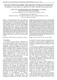
Figure 1 illustrates a backscatter-based multiple smart
sensor node and unmanned aerial vehicle-enabled MEC in
the IoT system. It comprises one ground-dedicated RF
station (denoted as S), one single-antenna UAV access
point (denoted as U), and K resource-constrained single-
antenna ground smart nodes (denoted as SNs). The U is
integrated with an edge server and hovers in the sky at an
altitude zU to assist smart nodes in executing their tasks. The
station S provides RF signals to SNs for employing BC.
Assuming that U and SNs operate in haft-duplex mode. The
static Cartesian coordinate is used to present the location of
the UAV and each node. Thus, we denote the location of
U as (xU, yU, zU), the location of kth SNk as (xk, yk, 0) with
{1,..., }kK
, and the location of S as (xS, yS, 0).
Figure 1. System model for BC-based multi-user
UAV-MEC IoT Network
We can model the signal fading in ground-to-air (G2A)
and air-to-ground (A2G) communication channels using
large-scale and small-scale fading. Large-scale fading
depends on the probability of a direct line-of-sight (LoS) or
indirect non-line-of-sight (NLoS) path, as described in [19].
Small-scale fading refers to rapid signal fluctuations due to
local effects, and we can represent it using the Nakagami-m
distribution with parameter m [20]. Now, considering the
probability of both LoS and NLoS links between the U and
the kth SNk, we can express the average path loss as:
( )
LoS NLoS
LoS 180
,,
1Uk
Uk Uk Uk Uk
a ab
dd
be
−+
−
=+
+
(1)
where
( ) ( )
22
2
Uk U k U k U
d x x y y z= − + − +
,

ISSN 1859-1531 - THE UNIVERSITY OF DANANG - JOURNAL OF SCIENCE AND TECHNOLOGY, VOL. 22, NO. 12, 2024 25
( )
arcsin
Uk U Uk
zd
=
,
stands for the path-loss
exponent,
a
and
b
represent parameters whose values
change based on the surrounding environment, and
( )
1
/4
A V c
cf
−
=
,
{LoS, NLoS}A
, denotes the
parameter depended on environment and carrier frequency
fc, c denotes the speed of light, and
V
represents the
excessive path loss of the LoS and NLoS propagation [21].
The channel coefficients of U-SNk, S-SNk and S-U links
are denoted as
Uk
h
,
Sk
h
and
SU
h
, respectively. The
cumulative distribution function (CDF) and the probability
density function (PDF) of corresponding power channel
gains,
2
||
Uk
h
,
2
||
Sk
h
and
2
||
SU
h
, are, respectively, as follows:
1
0
1
( ) 1 ,
!
XX
X
l
mm
x
X
X
lX
m
F x e x
l
−
−
=
=−
(2)
1
1
( ) ,
( 1)!
XX
XX
mmx
m
X
X
XX
m
f x x e
m
−
−
=
−
(3)
where
2 2 2
{| | | | | },,
Uk Sk SU
X h h h
,
[]
XX
=E
,
[.]E
stands for
expectation operator,
X
m
0.5 is the fading severity factor. For
simplicity,
22
12
| | | |
,
Sk Uk
hh
m m m m= =
,
21
||
Sk
h
=
,
22
||
Uk
h
=
,
{1,..., }kK
,
2
||
Uk Uk
gh=
,
2
||
Sk Sk
gh
=
and
2
||
SU SU
gh
=
.
3.2. Signal Models
In this study, a TDMA strategy is considered as Figure
2. For simplicity, the entire operation duration T is divided
into N equal time slots; thus, the time duration of each slot
is δ = T/N. The nth (
{1,..., }nN
) time slot with the length
of δ is divided again into K small time slots which is
denoted as
[]
kn
,
{1,..., }kK
. The length of each slot
depends on the offloading time for each SN.
Due to BC, the transmitted carrier signal, represented
as s[n], from the dedicated S, can cause an interference to
the received backscattered signal at U. This interference
can be eliminated by implementing perfect successive
interference cancellation (pSIC) at U. Therefore, the signal
received at U can be given by
[ ] [ ] [ ] [ ] [ ] [ ],
ks
k Sk Uk
Uk Sk
P
y n s n n h n h n w n
d
=+
(4)
Where, Ps is the transmit power of S,
(
01
)
denotes the backscattering reflection coefficient SNs,
[ ] {0,1}
kn
22
[ [ ] ] [ [ ] ] 1
k
s n n
==EE
,
[.]E
stands for the
expectation operator,
Sk
d
represents the Euclidean
distances from the
th
k
SN
to
S
, and w[n] denotes the
additive white Gaussian noise (AWGN), which has zero
mean and variance of σ2. The instantaneous signal-to-noise
ratio (SNR) received at U is obtained as
22
| | | | ,
s Sk Uk
k Sk Uk
Uk Sk
hh gg
d
==
(5)
where
2
=
ss
P
,
( )
= sUk Sk
d
.
Figure 2. Time diagram of work flow for our proposed system
3.3. Offloading and Edge Computing Models
In our work, a partial offloading scheme is considered.
In this scheme, the smart user nodes with limited energy
and computation resources can handle their partial tasks
locally and offload the remainders to U for processing
through deployed BC. We assume that the server at U
processes the tasks in a pipeline manner. Each SN’s task
can be divided into two independent
1k k k
LL
=
- bit and
2(1 )
k k k
LL
=−
-bit subtasks, where
01
k
is the task
dividing ratio and Lk represents the total bit length of the
kth SN's task. According to Figure 2, the workflow of this
proposed system is described as follows:
• During the duration
[]
kn
, the
th
k
SN
computes its
1k
L
-bit subtask locally and offloads its
2k
L
-bit remainder to
U
.
Throughout the remaining time, it harvests energy from
S
by
employing an RF power harvesting scheme. The corresponding
executing time at the
th
k
SN
can be expressed as
1,
ck k k k k
k
kk
c L c L
tff
==
(6)
where ck and fk denote the CPU cycles for node k to
compute one bit and its CPU-cycle frequency. The time
consumption for offloading is calculated as
( )
off 2
2
,
log 1
k
k
k
L
tW
=+
(7)
where W denotes the channel bandwidth for each user k.
• The U receives the offloading data from the kth SN,
denoted as
off
k
SN
, and processes the previous received data
from the
( 1)th
k−
SN
, denoted as
pro
1k−
SN
, simultaneously. In
other words, the offloading and computing routines for
each user are executed at
U
in two continuous time slots (
k
and
1k
+
). The corresponding executing time at the
U
is obtained as
2(1 ) ,
UU k U k k
k
UU
c L c L
tff
−
==
(8)
where cU and fU denote the CPU cycles per bit computing
and the CPU-cycle frequency of U's server.
Note: Assuming that the position of U remains nearly
unchanged during each time slot δ and across different time
slots, it can be moved. Accordingly, the position of U at
th
n
time slot is (
[]
U
xn
,
[]
U
yn
,
[]
U
zn
),
{1,..., }nN
. We
further assume that the time of result feedback to each
SN
is small compared to
[]
kn
. Thus, it is neglected.

26 Dac-Binh Ha, Van-Truong Truong, Tien-Vu Truong, Nguyen-Son Vo, Van Nhan Vo
3.4. Energy Models
In our work, we propose that the smart nodes can
harvests the RF energy from RF station. Thus, the
harvested energy of each SN is obtained as
( )
2
|| ,
h off c
Sk
k s k k
Sk
h
E P t t
d
= − −
(9)
where
01
denotes the energy conversion efficiency
of SN. Assuming that all SNs have the same energy
conversion efficiency. The smart nodes are designed so
that the harvested energy is utilized to compute the
1k
L
-
bit subtask, i.e.,
0
h
k
E
. According to [22], the energy
consumption of the kth SN is calculated as
22
1
( ) ( ) ,
c
k k k k k k k k k
E c f L c f L
==
(10)
where
stands for the effective capacitance coefficients
of CPU with relation to the CPU architecture in the kth SN.
Therefore, each task can be divided to satisfy
.
hc
kk
EE
(11)
In other words, we can select the value of task dividing
ratio,
k
, according to (9).
The energy consumption of U consists of two parts: One
is for computing (
c
U
E
) and other is for flying (
f
U
E
). The total
energy consumption for executing in U is obtained as
22
2
11
( ) ( ) (1 ) ,
KK
c
U U U U k U U U k k
kk
E c f L c f L
==
= = −
(12)
Where,
U
stands for the effective capacitance coefficients
of CPU with relation to the CPU architecture in U.
Consider UAV having multiple rotors, the power
consumed when flying in the sky due to gravity force can
given by [20]
3
()
,
2
fU
U
Wg
Pr
=
(13)
where,
U
W
stands for the UAV's weight,
g
is the standard
acceleration of gravity,
is the fluid air density,
is the
rotor disc area, and
n
is the number of rotors.
4. Performance Analysis
4.1. Successful Computation Probability (SCP)
This subsection analyzes the performance analysis
regarding SCP, denoted as . This criterion is the key
metric to evaluate the latency performance of MEC systems
[23]. SCP is the probability that the MEC latency, including
offloading time and computation time, is lower than the pre-
given time. Considering the condition of
0
h
k
E
, the SCP of
this considered system can be defined as follows:
( )
( )
( )
1
1
Pr max , 0
,
Pr , , 0 .
K
off th h
cU
k k k
kk
k
K
off c th off U th h
k k k k k k k
k
t T E
tt
t t T t t T E
=
=
= +
= + +
(14)
The approximately closed-form expression of SCP is
depicted as Theorem 1.
Theorem 1. The SCP of proposed backscatter-based
multi-user UAV-enable MEC IoT system is given by:
( )
1
21
21
1
1
0
112
1
2 2 ,
!( 1)!
m
K
ml
ml
l
klm
−
+
−
=
=
=
−
(15)
where
12
12
mm
=
,
( )
1 2 3
max , ,
=
,
2
()
121
k
th U
kk
L
W T t−
−=
,
2
()
221
k
th c
kk
L
W T t−
−=
,
3
=
2
()
21
k
c
k
L
Wt
−−
,
( )
.
is the modified Bessel function of the second kind
with
th
order.
Proof. See Appendix A.
4.2. Energy Outage Probability (EOP)
This subsection analyzes the performance analysis
regarding EOP of the considered system. The energy
outage event is determined as the event where the energy
consumption at each SN is larger than the harvested energy
(
h
k
E
), or the power consumption at
U
is larger than the
allocated energy budget accompanying each node,
th
k
E
.
Therefore, we obtain the EOP defined as follows:
off
1
1 Pr , .
K
c h f c th
k k U k U k
k
E E P t E E
=
= − +
(16)
The approximately closed-form expressions of EOP is
depicted as Theorem 2.
Theorem 2. The EOP of proposed backscatter-based
multi-user UAV-enable MEC IoT system is given by:
112
0, if ||
1, others,
c th c
K
U k k
k
E E t
II
=
=− +
(17)
where
( )
1
1
11
1
1!
m
m
m
=
−
,
1
.
c
k Sk
S
Ed
P
=
,
2,
th c
kU
f
U
EE
P
−
=
( )
2
1
21
k
c
k
L
Wt
x
x
−−
= −
,
2
2
21
k
L
W
= −
,
1
1c
k
t
=−
,
1
2
2
c
k
t
=− −
,
1
3
2
c
k
t
=− −
,
21
cos 2
q
q
xQ
−
=
,
( )
1
1exp
2
q
q
x
t
+
=−
,
( )
21
1
2
q
q
x
l
+
=−
,
( )
3
1exp
2
q
q
x
h
+
=−
,
Q
is the complexity-vs-accuracy
trade-off coefficient.
( )
( )
( )
( )
( )
( )
( )
( )
( )
( )
( )
1
11
2
1
2
1
1
1
12
2
2
01
22
2
1
1
1
21 2
2
12
01
2
12
ln ln
exp
11,
ln
!2
exp . ln
11,
!2
exp .
m
ml l
q q q
l
mQ
c
qk
q
lq
q
ml l
qq
l
mQ
c
qk
q
lq
q
q
t t t
mxt
t
l Q m
t
I
ll
mlt
l
mm
lQ ll
−
−−
−
==
−−
−
==
− −
−
− +
−
=
−
− +
−−
2
ISSN 1859-1531 - THE UNIVERSITY OF DANANG - JOURNAL OF SCIENCE AND TECHNOLOGY, VOL. 22, NO. 12, 2024 27
( )
( )
( )
( )
1
11
2
2
1
1
1
232
2
2
01
22
2
0,
ln
exp
11,
!2 1
exp ln
c
k
m
ml
qq
l
mQ
c
qk
lq
q
t
hh
Imxt
l Q m
h
−
−−
−
==
+
−
=−
− +
Proof. See Appendix B.
5. Numerical Results and Discussion
This section assessed the backscatter-based UAV-
enabled MEC IoT network's performance through SCP and
EOP using Monte Carlo simulations. Table 1 summarizes
the simulation parameters used [20].
Table 1. Typical values of simulation parameters
Parameters
Notation
Typical
values
The average transmit SNR
S
0 - 20 dB
The number of SN
K
2, 5, 10
The Nakagami-m severity factor
12
,mm
1, 2, 3
The energy conversion efficiency
0.1, 0.5, 0.9
The backscattering reflection
coefficient
0-1
The data dividing ratio
k
0-1
The carrier frequency
fc
2 GHz
The excessive path loss coefficients
LoS
,
NLoS
1, 20
The environment-based parameters
a, b
9.6177,
0.1581
The MEC servers CPU frequency at U
fU
2 GHz
The SN CPU frequency
fk
1 GHz
The number of CPU cycle to
compute 1 bit
ck, cU
2
The effective CPU architecture of
SN and U
k
,
U
10-23
The channel bandwidth
W
1 MHz
The threshold of SN latency
th
k
T
0.05, 0.1, 0.2 s
The stored energy budget
th
k
E
1 kJ
Standard acceleration of gravity
g
9.8 m/s2
Fluid density of air
1.225 kg/m3
The task length
L
50 – 500 kbit
Area of rotor disk
0.2 m2
Number of rotors
r
6
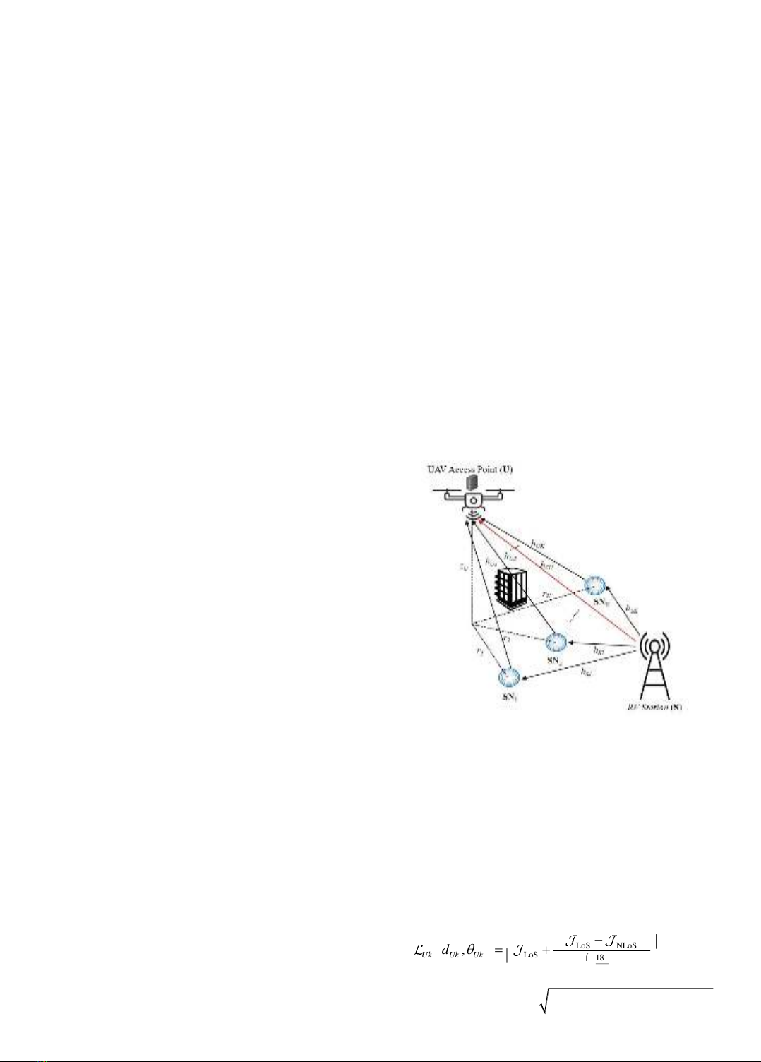
Figure 3 depicts the impact of critical parameters, average
transmit SNR (γS), on the system performance. Firstly, it is
observed that increasing γS leads to an enhancement in system
performance. In simpler terms, the SCP tends to improve as
the transmit power increases, whereas the EOP tends to
decrease. It indicates that there is no trade-off between these
two performance metrics. However, it is noteworthy that as
γS reaches a reasonably high level, the SCP saturates and the
EOP drops to deficient levels, indicating that the system's
performance improvement becomes limited. Furthermore,
Figure 3 investigates the impact of the Nakagami-m severity
factor, i.e., m1 and m2. The SCP associated with m1 = 1 and
m2 = 1 is the smallest, and the EOP is the largest; because, in
this case, the transmission channels follow Rayleigh fading.
Moreover, we observe that a higher severity factor m
corresponds to a better system because the channel quality
improves.
Figure 3. SCP and EOP versus the average transmit SNR with
different values of Nakagami-m severity factor
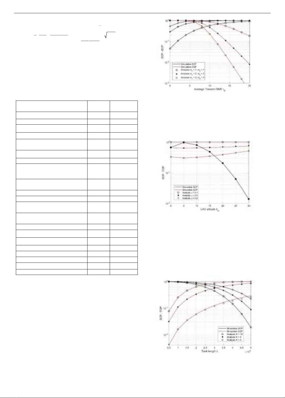
Figure 4 clarifies the impact of two parameters, the
UAV's altitude (hU) and the energy conversion efficiency
(η), on the system performance. The findings indicate the
presence of an optimal flight altitude for the UAV, which
yields the highest SCP and the lowest EOP.
Figure 4. SCP and EOP versus the UAV’s altitude with different
values of energy conversion efficiency
This phenomenon can be attributed to the dynamic
interaction between LoS and NLoS propagation as the
UAV's altitude varies. Therefore, the UAV's altitude
balances enhanced LoS connectivity and controlled
transmission losses. This trade-off culminates in
determining an optimal flight altitude that maximizes SCP
while minimizing EOP. In addition, the results also show
that increasing hU reduces EOP but does not affect SCP.
Figure 5. SCP and EOP versus the task length with
different values of number of SNs
Figure 5 depicts the impact of the task length (L) with
three different number of SN cases: K = 2, K = 5, and