4/2/2013
1
ĐI HC QUC GIA TP.H CHÍ MINH
TRƯNG ĐI HC BÁCH KHOA
KHOA ĐINĐIN T
B MÔN K THU!T ĐIN T
TP.H" Chí Minh 01/2013
X LÝ TÍN HiU S V1I FPGA
Chaper 4: Retiming
(Tái đ?nh thì)
GV: Hoàng Trang
Email: hoangtrang@hcmut.edu.vn
mr.hoangtrang@gmail.com
Thank to: thLy H" Trung MN
Slide: from text book of Parhi
11
Hoàng Trang
BM Đin TDSPFPGAchapter4 01/2013
Thut ng!
English Vietnamses
Pipelining t#o đư'ng (ng
Cutset tp c+t
Transposed SFG SFG chuy.n v0
Data broadcast truy2n d! liu kh+p nơi, phát tán d! liu
Parallel processing x lý song song
block processing x lý kh(i
communication bound gi:i h#n truy2n thông
th'i gian tr< truy2n thông
2
CuuDuongThanCong.com https://fb.com/tailieudientucntt
cuu duong than cong . com

4/2/2013
2
Hoàng Trang
BM Đin TDSPFPGAchapter4 01/2013
Outline
•Retiming Introduction
•Preliminaries
– Quantitative Description
– Properties of Retiming
– Solving systems of inequalities
•Special Cases
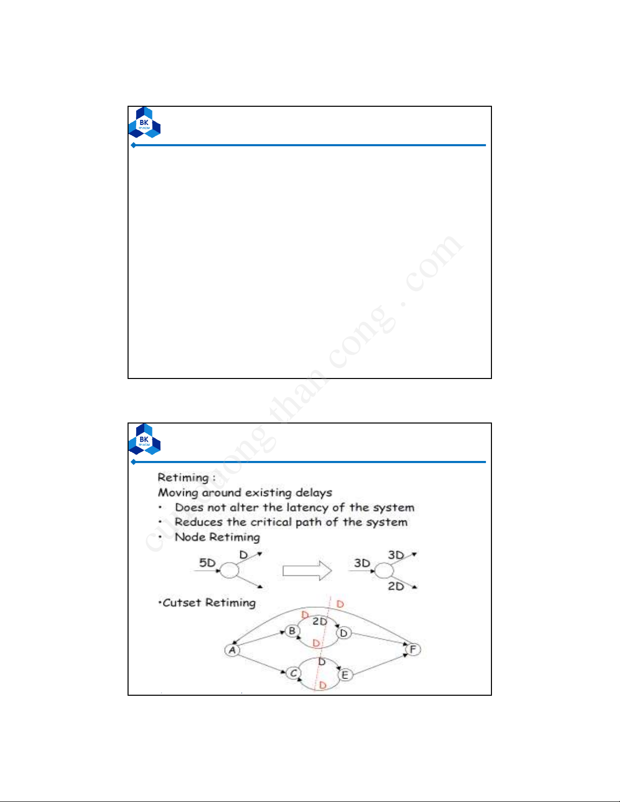
– Cutset Retiming
– Pipelining
•Uses of Retiming
– Retiming for Clock Period Minimization
– Retiming for Register Minimization
Hoàng Trang
BM Đin TDSPFPGAchapter4 01/2013
4.1 INTRODUCTION
•Retiming is a transformation technique used to
change the locations of delay elements in a circuit
without affecting the input/output characteristics of
the circuit.
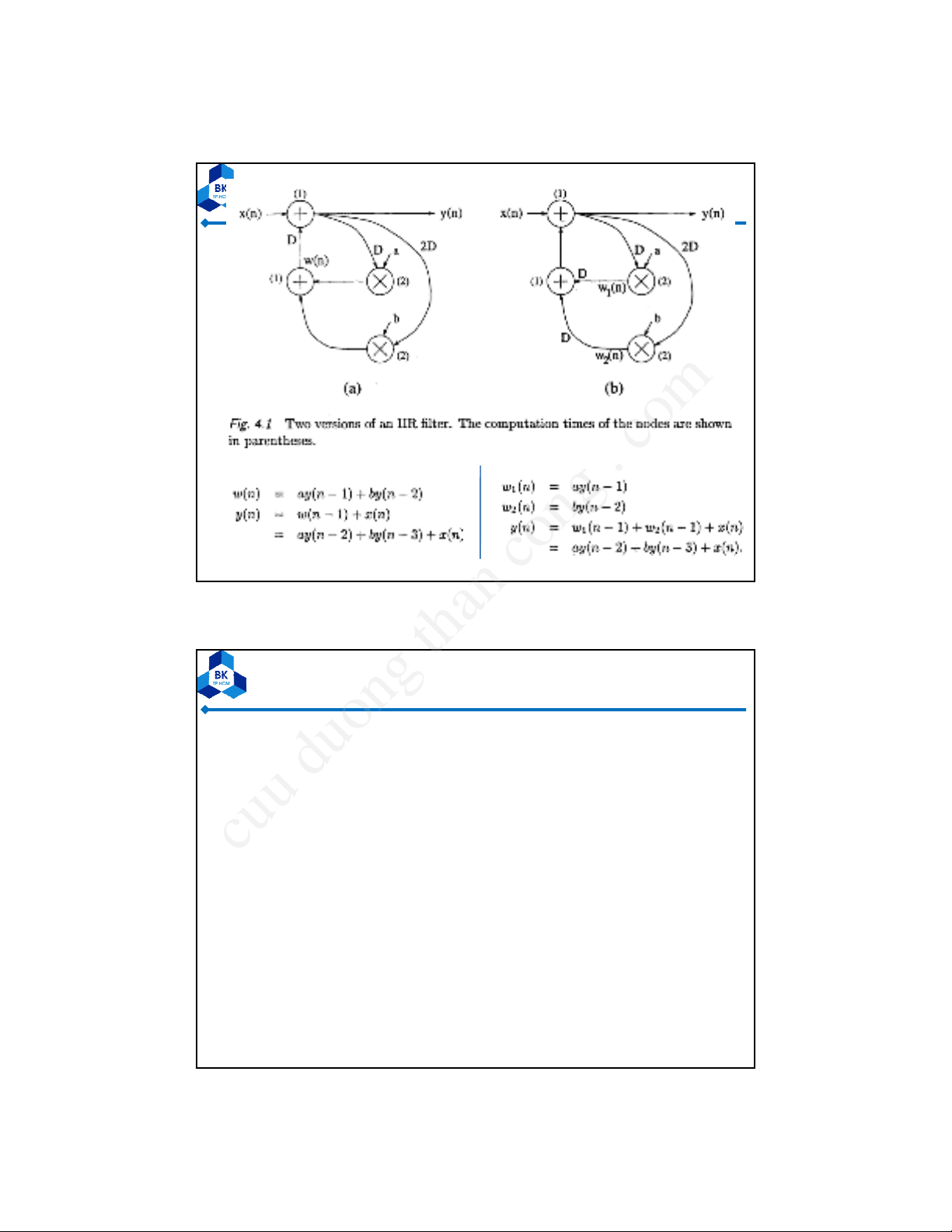
•For example, consider the IIR filters in Fig. 4.1(a) &
(b). Although the filters in Fig. 4.1(a) and Fig. 4.1(b)
have delays at different locations, these filters have
the same input/output characteristics. These 2
filters can be derived from one another using
retiming.
4
CuuDuongThanCong.com https://fb.com/tailieudientucntt
cuu duong than cong . com
4/2/2013
3
Hoàng Trang
BM Đin TDSPFPGAchapter4 01/2013 5
The filter in Fig. 4.1(b) is described byThe filter in Fig. 4.1(a) is described by
Example:
Hoàng Trang
BM Đin TDSPFPGAchapter4 01/2013
Applications of Retiming
•Retiming has many applications in synchronous circuit
design. These applications include
–reducing the clock period of the circuit,
–reducing the number of registers in the circuit,
– reducing the power consumption of the circuit, and
– logic synthesis
6
CuuDuongThanCong.com https://fb.com/tailieudientucntt
cuu duong than cong . com
4/2/2013
4
Hoàng Trang
BM Đin TDSPFPGAchapter4 01/2013
Applications of Retiming (cont’d)
•Retiming can be used to increase the clock rate of a circuit by
reducing the computation time of the critical path.
•For example:
– The critical path of the filter in Fig. 4.1(a) = TM+TA= 3 u.t. => this
filter cannot be clocked with a clock period of less than 3 u.t.
– The retimed filter in Fig. 4.1(b) = TA+TA= 2 u.t. => this filter can be
clocked with a clock period of 2 u.t.
– By retiming the filter in Fig. 4.1(a) to obtain the filter in Fig. 4.1(b), the
clock period has been reduced from 3 u.t. to 2 u.t., or by 33%.
•Retiming can be used to decrease the number of registers in a
circuit. The filter in Fig. 4.1 (a) uses 4 registers while the filter in
Fig. 4.1 (b) uses 5 registers.
•Since retiming can affect the clock period and the number of
registers, it is sometimes desirable to take both of these
parameters into account. 7
Hoàng Trang
BM Đin TDSPFPGAchapter4 01/2013 8
CuuDuongThanCong.com https://fb.com/tailieudientucntt
cuu duong than cong . com
4/2/2013
5
Hoàng Trang
BM Đin TDSPFPGAchapter4 01/2013
Example:
9
Hoàng Trang
BM Đin TDSPFPGAchapter4 01/2013
Retiming
•Generalization of Pipelining
•Pipelining is Equivalent to Introducing Many
delays at the Input followed by Retiming
10
CuuDuongThanCong.com https://fb.com/tailieudientucntt
cuu duong than cong . com


![Ngân hàng đề thi trắc nghiệm Kiến trúc máy tính [mới nhất]](https://cdn.tailieu.vn/images/document/thumbnail/2026/20260514/hoahongxanh0906/135x160/49281779160279.jpg)


%20--%3e%3cdefs%3e%3cstyle%3e%20.st0%20{%20fill:%20%23fff;%20}%20.st1%20{%20fill:%20%237800fa;%20}%20%3c/style%3e%3c/defs%3e%3cpath%20class='st1'%20d='M117.78,12.18H43.11c2.9,3.47,4.65,7.94,4.65,12.82,0,5.6-2.3,10.66-6.01,14.29h76.02l7.22-13.56-7.22-13.56Z'/%3e%3cg%3e%3cpath%20class='st0'%20d='M53.58,26.17h-.59v-1.46h.59v-4.96h2.83c1.78,0,2.67.94,2.67,2.82v5.76c0,1.87-.89,2.81-2.67,2.81h-2.83v-4.96ZM55.36,21.37v3.34h1.1v1.46h-1.1v3.34h1.01c.61,0,.91-.37.91-1.1v-5.93c0-.74-.3-1.1-.91-1.1h-1.01Z'/%3e%3cpath%20class='st0'%20d='M65.99,31.14h-1.8l-.31-2.07h-2.19l-.31,2.07h-1.64l1.82-11.39h2.62l1.82,11.39ZM65.28,18.04c-.25.46-.51.77-.75.94-.21.15-.47.22-.79.22-.26,0-.57-.07-.92-.22l-.38-.15c-.14-.05-.26-.07-.37-.07-.3,0-.53.18-.71.54l-.91-.68c.25-.46.51-.77.75-.94.21-.14.48-.21.79-.21.26,0,.57.07.92.21l.38.15c.14.05.26.07.37.07.3,0,.53-.18.71-.54l.91.68ZM61.91,27.52h1.73l-.87-5.76-.87,5.76Z'/%3e%3cpath%20class='st0'%20d='M74.53,26.89v1.52c0,1.91-.89,2.86-2.67,2.86s-2.67-.95-2.67-2.86v-5.93c0-1.91.89-2.86,2.67-2.86s2.67.95,2.67,2.86v1.11h-1.69v-1.22c0-.75-.31-1.12-.93-1.12s-.93.37-.93,1.12v6.15c0,.74.31,1.11.93,1.11s.93-.37.93-1.11v-1.63h1.69Z'/%3e%3cpath%20class='st0'%20d='M81.4,31.14h-1.8l-.31-2.07h-2.19l-.31,2.07h-1.64l1.82-11.39h2.62l1.82,11.39ZM75.9,19.2l1.52-1.91h1.71l1.51,1.91h-1.61l-.76-.95-.75.95h-1.61ZM77.32,27.52h1.73l-.87-5.76-.87,5.76ZM83.1,15.99l-1.76,1.91h-1.26l1.17-1.91h1.86Z'/%3e%3cpath%20class='st0'%20d='M84.86,19.75c1.78,0,2.67.94,2.67,2.82v1.48c0,1.87-.89,2.81-2.67,2.81h-.85v4.28h-1.79v-11.39h2.64ZM84.01,21.37v3.86h.85c.58,0,.87-.36.87-1.08v-1.71c0-.71-.29-1.07-.87-1.07h-.85Z'/%3e%3cpath%20class='st0'%20d='M93.51,19.75c1.78,0,2.67.94,2.67,2.82v1.48c0,1.87-.89,2.81-2.67,2.81h-.85v4.28h-1.79v-11.39h2.64ZM92.66,21.37v3.86h.85c.58,0,.87-.36.87-1.08v-1.71c0-.71-.29-1.07-.87-1.07h-.85Z'/%3e%3cpath%20class='st0'%20d='M98.8,31.14h-1.79v-11.39h1.79v4.88h2.03v-4.88h1.83v11.39h-1.83v-4.88h-2.03v4.88Z'/%3e%3cpath%20class='st0'%20d='M105.36,24.55h2.46v1.62h-2.46v3.34h3.09v1.63h-4.88v-11.39h4.88v1.63h-3.09v3.18ZM108.17,17.29l-1.76,1.91h-1.26l1.17-1.91h1.86Z'/%3e%3cpath%20class='st0'%20d='M112.2,19.75c1.78,0,2.67.94,2.67,2.82v1.48c0,1.87-.89,2.81-2.67,2.81h-.85v4.28h-1.79v-11.39h2.64ZM111.35,21.37v3.86h.85c.58,0,.87-.36.87-1.08v-1.71c0-.71-.29-1.07-.87-1.07h-.85Z'/%3e%3c/g%3e%3ccircle%20class='st1'%20cx='25'%20cy='25'%20r='20'/%3e%3cpath%20class='st0'%20d='M32.78,19.27c2.92,0,4.43,2.55,5.28,5.33l.71,2.17c.14.38-.33.75-.71.75h-5.61c.19-.33.24-.71.09-1.08l-.75-2.45c-.43-1.32-.99-2.64-1.79-3.77.75-.57,1.65-.94,2.78-.94h0ZM25,18.38c3.25,0,4.9,2.78,5.89,5.89l.76,2.45c.14.42-.33.8-.8.8h-11.69c-.42,0-.94-.38-.8-.8l.75-2.45c.99-3.11,2.64-5.89,5.89-5.89h0ZM25,11.35c1.74,0,3.11,1.37,3.11,3.11s-1.37,3.11-3.11,3.11-3.11-1.41-3.11-3.11,1.41-3.11,3.11-3.11h0ZM17.27,19.27c1.08,0,1.98.38,2.73.94-.8,1.13-1.37,2.45-1.74,3.77l-.8,2.45c-.14.38-.05.75.09,1.08h-5.56c-.42,0-.9-.38-.75-.75l.71-2.17c.9-2.78,2.41-5.33,5.33-5.33h0ZM17.27,12.91c1.51,0,2.78,1.27,2.78,2.83s-1.27,2.83-2.78,2.83-2.83-1.27-2.83-2.83,1.27-2.83,2.83-2.83h0ZM32.78,12.91c1.56,0,2.78,1.27,2.78,2.83s-1.23,2.83-2.78,2.83-2.83-1.27-2.83-2.83,1.27-2.83,2.83-2.83h0ZM27.07,28.56v.09c0,.57-.24,1.08-.61,1.46h0v.05c-.38.33-.9.57-1.46.57s-1.08-.24-1.46-.61h0c-.38-.38-.61-.9-.61-1.46v-.09h1.41v.09c0,.19.05.38.19.47v.05c.09.09.28.19.47.19s.38-.09.47-.19v-.05c.14-.09.24-.28.24-.47t-.05-.09h1.41ZM30.99,28.56v.09c0,1.65-.66,3.16-1.74,4.24-1.08,1.08-2.59,1.79-4.24,1.79s-3.16-.71-4.24-1.79l-.05-.05c-1.04-1.08-1.7-2.55-1.7-4.2v-.09h1.41v.09c0,1.27.47,2.4,1.27,3.25h.05c.85.85,1.98,1.37,3.25,1.37s2.4-.52,3.25-1.37c.85-.8,1.37-1.98,1.37-3.25v-.09h1.37ZM34.99,28.56v.09c0,2.78-1.13,5.28-2.92,7.07-1.79,1.79-4.29,2.92-7.07,2.92s-5.23-1.13-7.07-2.92c-1.79-1.79-2.92-4.29-2.92-7.07v-.09h1.41v.09c0,2.4.94,4.53,2.5,6.08,1.56,1.56,3.72,2.5,6.08,2.5s4.52-.94,6.08-2.5c1.56-1.56,2.5-3.68,2.5-6.08v-.09h1.41Z'/%3e%3c/svg%3e)