REGULAR ARTICLE
New composite material based on heavy concrete reinforced
by basalt-boron ber for radioactive waste management
Iryna Romanenko
1
, Maryna Holiuk
1
, Pavlo Kutsyn
1
, Iryna Kutsyna
1
, Hennadii Odynokin
1
, Anatolii Nosovskyi
1
,
Vitalii Pastsuk
2
, Madis Kiisk
2
, Alex Biland
3
, Yurii Chuvashov
4
, and Volodymyr Gulik
1,2,*
1
Nuclear facility safety department, Institute for Safety Problems of Nuclear Power Plants, Lysogirska 12, 03142 Kyiv, Ukraine
2
Institute of Physics, University of Tartu, W. Ostwaldi 1, 50411 Tartu, Estonia
3
US Basalt Corp., Richmond, TX 77407, USA
4
Institute for Problems in Materials Science, Krzhizhanovsky 3, 03142 Kyiv, Ukraine
Received: 15 August 2019 / Accepted: 2 September 2019
Abstract. A new composite material with neutron radiation shielding properties is presented. This ber
reinforced concrete material incorporates basalt-boron ber, with different concentrations of boron oxide in
ber, and is applicable to nuclear energy and nuclear waste management. The methodology for production of
boron oxide (B
2
O
3
) infused basalt ber has been developed. First experimental samples of basalt boron ber
containing 6% of B
2
O
3
and 12% B
2
O
3
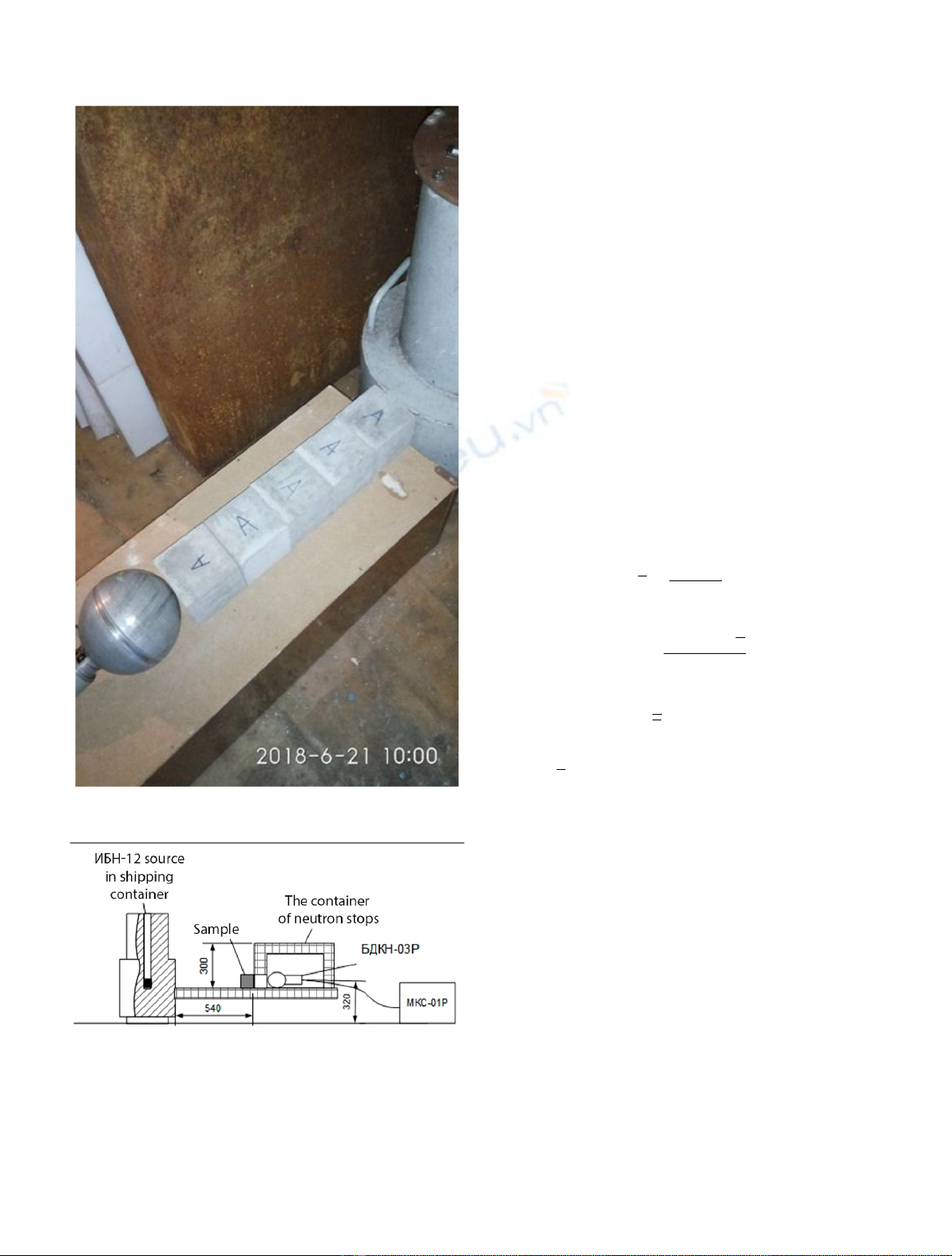
have been produced in laboratory conditions. The concrete samples
reinforced by two types of basalt-boron ber with different dosages have been prepared for neutron experiment.
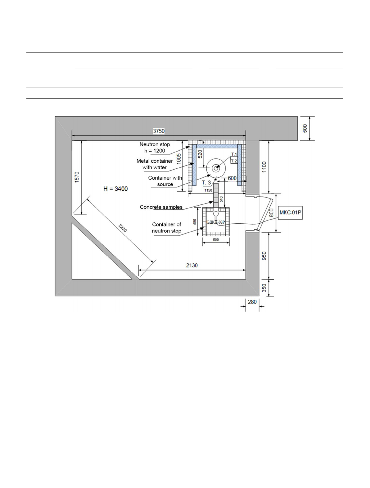
The neutron experimental investigations on radiation shielding properties of concrete reinforced by basalt-boron
ber have been performed by means of Pu-Be neutron source. The prepared samples have been tested in the
course of several series of tests. It is shown that basalt-boron bers in concrete improve neutron radiation
shielding properties for neutrons with different energies, but it appears to be most effective when it comes to
thermal neutrons.
1 Introduction
For safe operation of various sources of radioactivity, it is
necessary to have reliable radiation protection. To date,
there are many different types of radiation sources in the
world, such as conventional ssion reactors, fusion neutron
sources, DD and DT neutron generators, plasma focus
devices used as neutron sources and many gamma sources
[1,2]. These radiation sources are used for industrial,
scientic and medical purposes.
At the moment, there are different types of radiation
shielding. The most widespread is heavy concrete with
various additives [312]. Such heavy concrete should have
radiation shielding properties, both against neutron and
gamma irradiation. For example, in order to protect
against gamma radiation, we need to use materials with
large values of the atomic number Z [13]. As a result, for
protection against gamma radiation, llers are used most
widely, among them such natural minerals as barite
containing a lot of barium, magnetite, which consists of
titanium and iron, and serpentinite. For VVER reactors,
heavy concrete with serpentinite is used as biological
shielding [14]. Serpentinite contains such heavy elements as
iron and magnesium.
In addition to heavy minerals, concrete should contain
elements that are well scattering and absorb neutrons. By
default, the concrete contains a large amount of hydrogen, on
the nuclei of which effective neutron scattering is observed.
In this paper, the authors suggest a new type of
composite material based on heavy concrete reinforced by
improved basalt-boron ber (BBF), in which the boron
oxide is added during the production process.
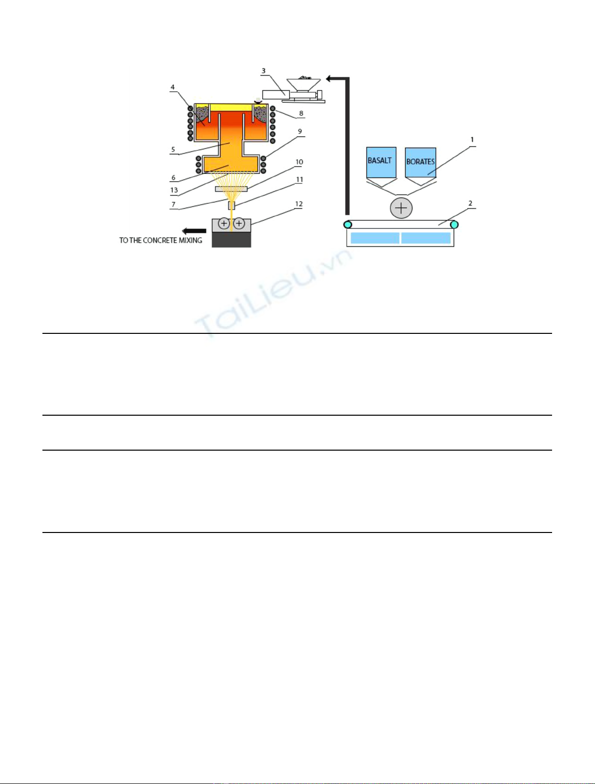
2 Basalt-boron ber
The proposal to add a basalt ber (BF) containing boron is
based on the fact that there is enough hydrogen in the
concrete to slow down fast neutrons, and if we add a
material with a large neutron absorption cross section (for
example, B-10), then it can become very effective material
with neutron radiation shielding properties [14].
Basalt ber is produced similarly to glass ber. The BF
production contains several stages: the preparation of the
basalt rock, the melting, the formation of ber, the drying of
the ber, cutting the ber and obtaining nal products [15].
*e-mail: volodymyr.gulik@gmail.com
EPJ Nuclear Sci. Technol. 5, 22 (2019)
©I. Romanenko et al., published by EDP Sciences, 2019
https://doi.org/10.1051/epjn/2019050
Nuclear
Sciences
& Technologies
Available online at:
https://www.epj-n.org
This is an Open Access article distributed under the terms of the Creative Commons Attribution License (https://creativecommons.org/licenses/by/4.0),
which permits unrestricted use, distribution, and reproduction in any medium, provided the original work is properly cited.
However, the process of BBF production is easier than
the production of glass ber: it does not require a
complicated and expensive process of preparation of the
charge, but requires only one supply line of crushed basalt
rocks in the furnace for melting. The basalt breed is rst
crushed, then washed, dried and loaded into containers
attached to the heater, which mixes the basalt to the
melting bath in gas ovens (see Fig. 1).
A number of studies have shown that concrete reinforced
with BF has high chemical and corrosion resistance,
durability, resistance to abrasion, and frost resistance
[1,1317]. Since the specic density of the BF is approxi-
mately the same as that of the main components of the
concrete, it is evenly distributed over the entire volume of
concrete in the form of steel and other types of polymer ber.
The rst experimental samples of BBF were prepared in
Institute for Problems in Materials Science in Ukraine for
two different types of basalt bers infused with boron as
reinforcing material. The rst type of BBF, hereinafter
referred to as BasBor6, contains 6% of B
2
O
3
, of which 19.8%
B-10 and 80.2% B-11. The second type of BBF, represented
in the text as BasBor12, contains 12% of B
2
O
3
,ofwhich
19.8% B-10 and 80.2%B-11. The chemical compositionof the
BBF with the infusion of boron BasBor6 is displayed on
Table 1. The chemical composition of the BBF with the
infusion of boron BasBor12 is displayed in Table 2.
3 Radiation shielding properties experiment
for Pu-Be neutron source
3.1 Description of experiment
For measurements a plutonium-beryllium neutron source,
(3#=-12) was used, creating a ux of fast neutrons with
Fig. 1. Scheme of the process for BBF production. (1) Metering & mixing equipment (batch preparation). (2) Conveying equipment.
(3) Batch charger. (4) Melting chamber. (5) Conditioning chamber. (6) Fiber forming chamber. (7) Fibers strand. (8) Induction coil of
melting chamber. (9) Induction coil of ber forming chamber. (10) Sizing applicator. (11) Gathering shoe. (12) Direct chopper.
(13) Fiber drawing plate [13].
Table 1. The chemical composition of BBF type BasBor6.
Main constituents B
2
O
3
Na
2
O MgO Al
2
O
3
SiO
2
P
2
O
5
SO
3
Cl
% 6.2 1.809 5.93 13.888 50.40 0.125 0.015 0.010
Main constituents K
2
O CaO TiO
2
V
2
O
5
MnO Fe
2
O
3
Co
2
O
3
NiO
% 1.439 8.040 1.134 0.08 0.164 10.590 0.0033 0.002
Main constituents CuO ZnO Ga
2
O
3
Rb
2
O SrO Y
2
O
3
ZrO
2
BaO
% 0.003 0.014 0.002 0.0067 0.0349 0.006 0.0032 0.03
Table 2. The chemical composition of BBF type BasBor12.
Main constituents B
2
O
3
Na
2
O MgO Al
2
O
3
SiO
2
P
2
O
5
SO
3
Cl
% 11.7 1.715 5.66 13.120 47.64 0.117 0.010 0.008
Main constituents K
2
O CaO TiO
2
V
2
O
5
MnO Fe
2
O
3
Co
2
O
3
NiO
% 1.313 7.421 1.044 0.051 0.149 9.688 0.0028 0.003
Main constituents CuO ZnO Ga
2
O
3
Rb
2
O SrO Y
2
O
3
ZrO
2
BaO
% 0.0028 0.012 0.003 0.0061 0.0313 0.005 0.0029 0.03
2 I. Romanenko et al.: EPJ Nuclear Sci. Technol. 5, 22 (2019)
isotropic distribution and intensity 5 10
7
neutrons s
1
.
Table 3 shows its main technical characteristics.
Measurements of the neutron ux were carried out with
a radiometer-dosimeter МКC-01Ρwith a detection unit
#)К=-03Ρ. The apparatus measurement error of the
МКC-01Ρwhen measuring the neutron ux does not exceed
20 %. Measurements of neutron ux were carried out in two
types of the neutron energy spectrum:
for thermalneutrons;
for intermediate and fast neutrons (with cadmium
attachment to the detecting unit).
The measurements were carried out for two conditions
of irradiation of the samples, in different geometries:
concrete samples are placed in an isotropic neutron eld
from a Pu-Be neutron source (simpleneutron experi-
ment);
measurements with geometry, allowing to take into
account the reected and scattered neutrons (complex
neutron experiment).
During the measurements, the neutron source 3#=-12
was in the transport container. The transport container is a
metal container with a central tube into which the source is
installed. The inner space of the container is lled with
parafn. For personnel protection, a container with a
source from three sides was surrounded by panels of
neutron stopsof type ТΡ12-41-MMS 065/73 and metal
tanks with water. Neutron stopsare blocks of polyeth-
ylene with boron content and are effective neutron
absorbers. The thickness of the neutron-stop panels is
70 mm. Water tank thickness 150 mm.
The oor plan and layout of equipment is shown in
Figure 2, and Figure 3 shows a front view of the source and
the overall dimensions of the equipment.
Table 3. The main technical characteristics of neutron source.
Source type Source dimensions (active part), mm Neutron intensity,
neutrons s
1
Maximum activity
Pu-239 at source
Diameter,
D(d)
Height (Length)
H(h), (L)
Bq Ci
3#=-12 54 (46) 64 (46) (5.0 ± 1.0) 10
7
1.3 10
12
35
Fig. 2. Layout of the room and equipment placement during measurements.
I. Romanenko et al.: EPJ Nuclear Sci. Technol. 5, 22 (2019) 3
As mentioned above, this study investigates two
different types of basalt bers infused with boron as
reinforcing material (BasBor6 and BasBor12). There are
5 types of concrete mixtures in the neutron experiment
conducted, all of them with same type of cement, CEM I
42.5R, same water-to-cement ratio and same river sand as
ne aggregate. The density of concrete was 2.33 g/cm
3
. All
in all, there are ve main types of concrete mixtures in this
study and they are noted throughout the paper as follows:
Rplain concrete without BBF; Aconcrete with
BasBor6 dosage: 5 kg/m
3
;Bconcrete with BasBor6
dosage: 20 kg/m
3
;Cconcrete with BasBor12 dosage:
5 kg/m
3
;Dconcrete with BasBor12 dosage: 30 kg/m
3
.
Concrete samples have dimensions: 10 cm 10 cm 10 cm.
3.2 Simpleexperiment
The scheme of measurement of geometry in a simple
experiment is shown in Figure 4. The detecting unit was
located along the axis and at the height of the source in the
containers. The distance between the detecting unit and
the front wall of the container is L = 500 mm.
Ten measurements were conducted without samples of
concrete. The measurements were carried out for thermal
(see Fig. 5) as well as intermediate and fast neutrons (using
a detection unit with an installed cadmium packing (see
Fig. 6)).
Between the detecting unit and the source, one to ve
concrete samples from each set were sequentially installed.
Ten measurements were conducted for each conguration
and set of samples. The measurements were carried out for
thermal as well as intermediate and fast neutrons (a
detection unit with an installed cadmium packing). All
experimental and simulations results will be presented in
next journal paper which is currently being prepared.
3.3 Complexexperiment
A diagram of the measurement geometry in a complex
experiment is shown in Figure 7.
For measurements, a container was assembled from
neutron stops. The container is a box with dimensions of
580 500 300 mm closed on all sides, with wall thickness
Fig. 3. Frontal view and overall dimensions of the container with
a neutron source.
Fig. 4. Schematic representation of measurement geometry in a
simpleexperiment.
Fig. 5. The measurements for thermal neutrons.
4 I. Romanenko et al.: EPJ Nuclear Sci. Technol. 5, 22 (2019)
70 mm. In one of the walls of the container, a rectangular
opening with a section equal to the section of the samples is
made. A detection unit was installed inside the container
opposite the opening. This measurement geometry allows
shielding from neutrons reected from the walls of the room
and equipment, and taking into account their contribution
to the measurement results of neutron ux.
The hole in the container was closed with a stopper
made of neutron stops and 10 measurements of w
ф
background neutron ux were performed. The measure-
ments were carried out for thermal as well as intermediate
and fast neutrons (a detection unit with an installed
cadmium packing).
Ten measurements of neutron ux w
0
were conducted
without samples of concrete. The measurements were
carried out for thermal as well as intermediate and fast
neutrons (a detection unit with an installed cadmium
packing).
Opposite the opening between the detection unit and
the source, one to ve concrete samples from each set were
sequentially installed. Ten measurements of neutron ux
were then conducted for each conguration and set of
samples. The measurements were carried out for thermal as
well as intermediate and fast neutrons (a detection unit
with an installed cadmium packing).
Based on the results obtained of neutron ux density
measurements, the mean values, the standard deviation
and the relative statistical error of each measurement by
formulas (1)(3) were calculated.
¼Pi¼n
i¼1i
n;ð1Þ
s¼ffiffiffiffiffiffiffiffiffiffiffiffiffiffiffiffiffiffiffiffiffiffiffiffi
Pi¼n
i¼1i
n1
s;ð2Þ
d¼2s
ffiffiffi
n
p100%;ð3Þ
where, imeasured values of neutron ux, neutron/
(cm
2
sec); the average value of neutron ux, neutron/
(cm
2
sec); n= 10 is the number of measurements; s
standard deviation, neutron/(cm
2
sec); dis the limit of the
relative statistical error, percentage.
The results of measurements and calculations in the
complexexperiment for all series of measurements
are given in Tables 4 and 5. The numbers 15 mean that:
1one concrete sample between source and detector;
2two concrete samples between source and detector; 3
three concrete samples between source and detector; 4
four concrete samples between source and detector; 5 ve
concrete samples between source and detector.
It can be seen from Table 4 that there is a slight increase
of neutron radiation shielding properties (up to 5%) in the
case of low concentrations of BBF in concrete (A and C
types of concrete samples), but considerable increase of
neutron radiation shielding properties (up to 13%) with the
addition of higher concentration of BBF in concrete (B and
D types of concrete samples) for intermediate and fast
neutrons. It can also be noted from Table 5 that a similar
trend can be observed for thermal neutrons, which is a
direct result of the increased fraction of neutrons with high
absorption cross-section for Boron-10 in the thermal
Fig. 6. The measurements for intermediate and fast neutrons.
Fig. 7. Schematic representation of the measurement geometry
in a complexexperiment.
I. Romanenko et al.: EPJ Nuclear Sci. Technol. 5, 22 (2019) 5