
* Corresponding author. Tel.: +98 21-61 118 572, Fax: +98 21-88 617 087
E-mail addresses: a_torabi@ut.ac.ir (A.R. Torabi)
© 2013 Growing Science Ltd. All rights reserved.
doi: 10.5267/j.esm.2013.06.002
Engineering Solid Mechanics 1 (2013) 27-36
Contents lists available at GrowingScience
Engineering Solid Mechanics
homepage: www.GrowingScience.com/esm
Determination of permissible defect size for solid axles loaded under fully-reversed rotating
bending
A.R. Torabia* and M.R.M. Alihab
aFracture Research Laboratory, Faculty of New Science and Technologies, University of Tehran, P.O. Box 13741-4395, Tehran, Iran
bWelding and Joining Research Center, School of Industrial Engineering, Iran University of Science and Technology (IUST), Narmak, 16846-13114,
Tehran-Iran
A R T I C L E I N F O A B S T R A C T
Article history:
Received January 15, 2013
Received in Revised form
March, 26, 2013
Accepted 18 June 2013
Available online
29 June 2013
The aim of the present work was to develop a guideline for approving the railway axles made of
C35 steel and containing surface and/or in-body defects after manufacturing. First, several
through and part-through circular cracks were modeled on the surface and in the body of the
axle at its critical cross-section. Then, the permissible size of such cracks was determined by
using the fracture mechanics. To verify the validity of the guideline, the theoretical result for
the semi-circular surface crack was compared with the allowable size prescribed by the
international railway standard. A very good agreement was found to exist between the predicted
and the standard values.
}}
© 2013 Growing Science Ltd. All rights reserved.
Keywords:
Defect
Crack growth
C35 steel
Fatigue
Four-point bending
Fracture Mechanics
1. Introduction
Railway axle is a safety critical component in the train load-carrying system that it is always designed
to be in service typically up to 30 years. This component transmits the vehicle weight to the wheels
and due to its rotation; it is subjected to fatigue loading conditions. The alternating stresses applied to
the axle result in fatigue crack initiation from the axle surface and then crack growth till final abrupt
fracture.
The fatigue failure of railway axles has been frequently investigated by the researchers as a common
cause of derailment both theoretically and experimentally. The fatigue failure of a railway axle in
Turkey railway transportation system has been theoretically studied in Bayrakter et al. (2010). The
influences of surface defects and inclusions on the life of a failed railway axle has been studied in

28
Alihosseini and Dehghani (2010) and revealed that the axle has been very sensitive to the surface
machining scratches even if they are very small. Makino et al. (2011) reviewed the fatigue damage
tolerance of high-speed railway axles in Japan railway network and the crack growth behavior of an
induction-hardened axle has been assessed based on the fracture mechanics. The fracture mechanics
has also been utilized by Beretta et al. (2005) for investigating the fatigue fracture of railway axles.
Beretta and coworkers (2011) have also investigated corrosion-fatigue in full scale railway axle in
A1T mild steel using three-point rotating bend loading with the artificial rainwater as corrosive
environment. Moreover, basic fatigue crack growth data both in the range of stable crack propagation
and near the threshold have been experimentally determined in Luke et al. (2005) for the heat-treated
railway axle steels under constant and variable amplitude loading at corresponding stress ratios. Other
technical reports (e.g. Zerbst et al. 2005 and 2011, Madia. et al. 2008, Luke et al. 2010, Linhart and
Cerny 2011, Beretta and Carboni 2011) dealing with investigating the fatigue failure of railway axles
can be referred which most of the failures start from the positions of stress concentrations such as
notches, defects, cracks and scratches.
After manufacturing, various types of stress concentrators such as metallic and non-metallic
inclusions, voids, defects and scratches are sometimes recognized in the axle that some of these
discontinuities may lead to premature failure. Hence, derailment and other possible events may occur.
Now days, beside experience, the criticality of such pre-existing defects can be accurately determined
thanks to the fracture mechanics as the main knowledge in damage tolerant design. Since cracks
having sizes larger than permitted would propagate and lead to axle premature fatigue failure, it is
necessary to check the axle health prior to its service to see if the size of likely detected defects is
within the allowable range.
In this work, the attempt was made to determine the permissible defects size for the railway axles.
The idea to do this work was started from the point that the permissible defect size prescribed by the
international railway standard UIC 811-1 (1983) is unique and it is not clear enough that whether or
not it is for part-through surface cracks at the critical section of the axle. If yes, what about the axles
containing no surface defect and having instead flaws located completely in the axle body and behave
as through cracks? To answer these important questions, first, a part-through semi-circular surface
crack and several part-through and through circular cracks were modeled in the axle critical section.
Then, the permissible size of such cracks was determined in various positions between the axle
surface and its center by comparing the value of the stress intensity factors with the value of the
fatigue crack propagation threshold of the material as a possible criterion. To evaluate the
computations, the permissible size obtained theoretically for the semi-circular crack was compared
with that suggested by the international railway standard UIC 811-1 (1983). The results showed that
the determined value was in a very good consistency with the standard value. Although there were
not general reference standard values of allowable size for through defects, the presented approach
and the obtained results could be satisfactorily trusted because all of the computations (including for
semi-circular crack) were carried out in a same manner.
2. Axel specifications
2.1. Geometry and loading
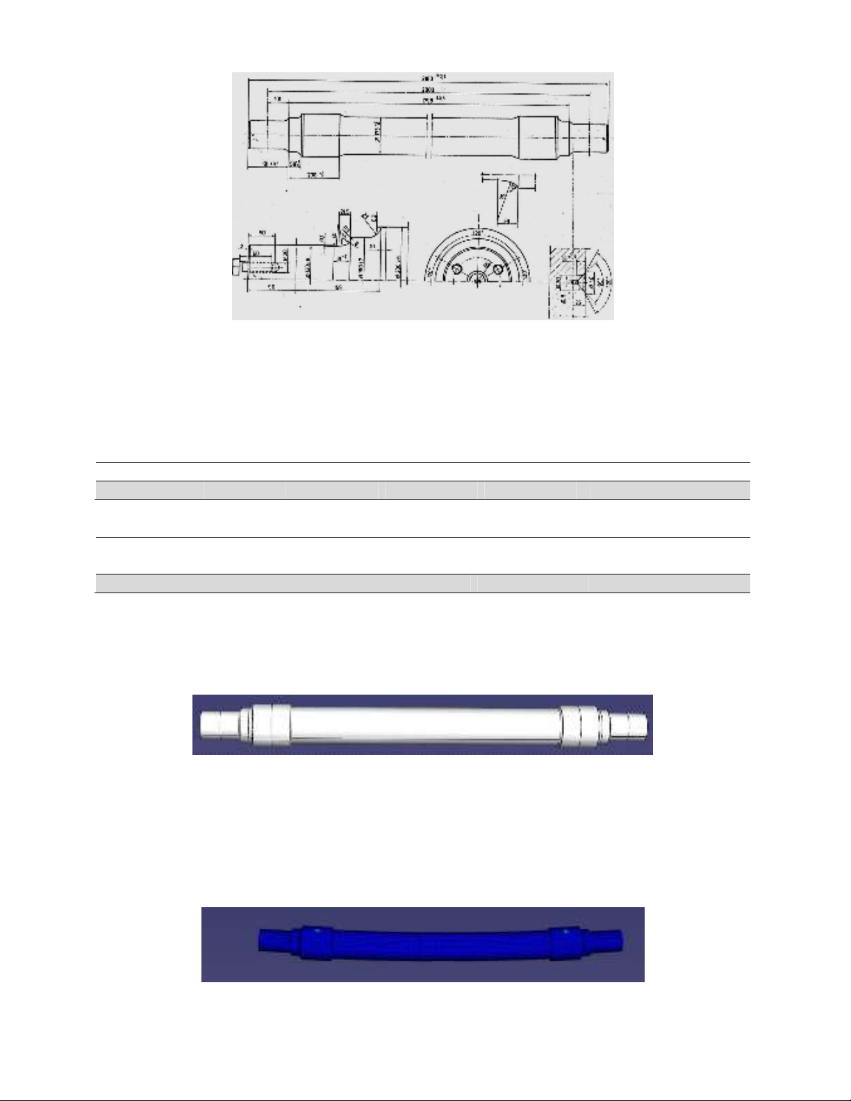
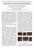
A detailed view of the studied axle is shown in Fig. 1 (given from Iran railway research center-
IRRC, 2000). As seen in this figure, the solid shaft has been made enbloc and its cross-section is
circular. In several locations on the shaft, fillets with different radii are seen which act as the stress
concentrators. The total vehicle weight was 225 kN and it was equally applied to the shaft in two
symmetric positions (112.5 kN concentrated load for each wheel location with diameter of 200 mm in
Fig. 1). The axle was constrained with two bearings at its right and left ends and hence, the shaft was
subjected to four-point rotating bending.
A.R. Torabi and M.R.M. Aliha / Engineering Solid Mechanics 1 (2013)
29
Fig. 1. Detail of the axle geometry (IRRC, 2000)
2.2. Material
The material used for fabricating the axle was carbon steel C35. The chemical composition and the
general mechanical properties of the material are presented in Tables 1 and 2, respectively.
Table 1. Chemical composition of the material
Component C Mn Si Ni Cr Others
Content (%) 0.37 1.12 0.46 0.3 0.3 0.08
Table 2. General mechanical properties of the material
Property Yield strength
(MPa)
Ultimate tensile
strength (MPa)
Elongation
(%)
Elastic
modulus (GPa)
Poisson’s
ratio
Hardness
(HB)
Value
320
520
22
203
0.3
175
3. Stress analysis
In order to determine the stress distribution in the shaft, first, a 3-D model was created for the axle
according to its geometry presented in Fig. 1. The model is shown in Fig. 2.
Fig. 2. A 3-D model of the axle
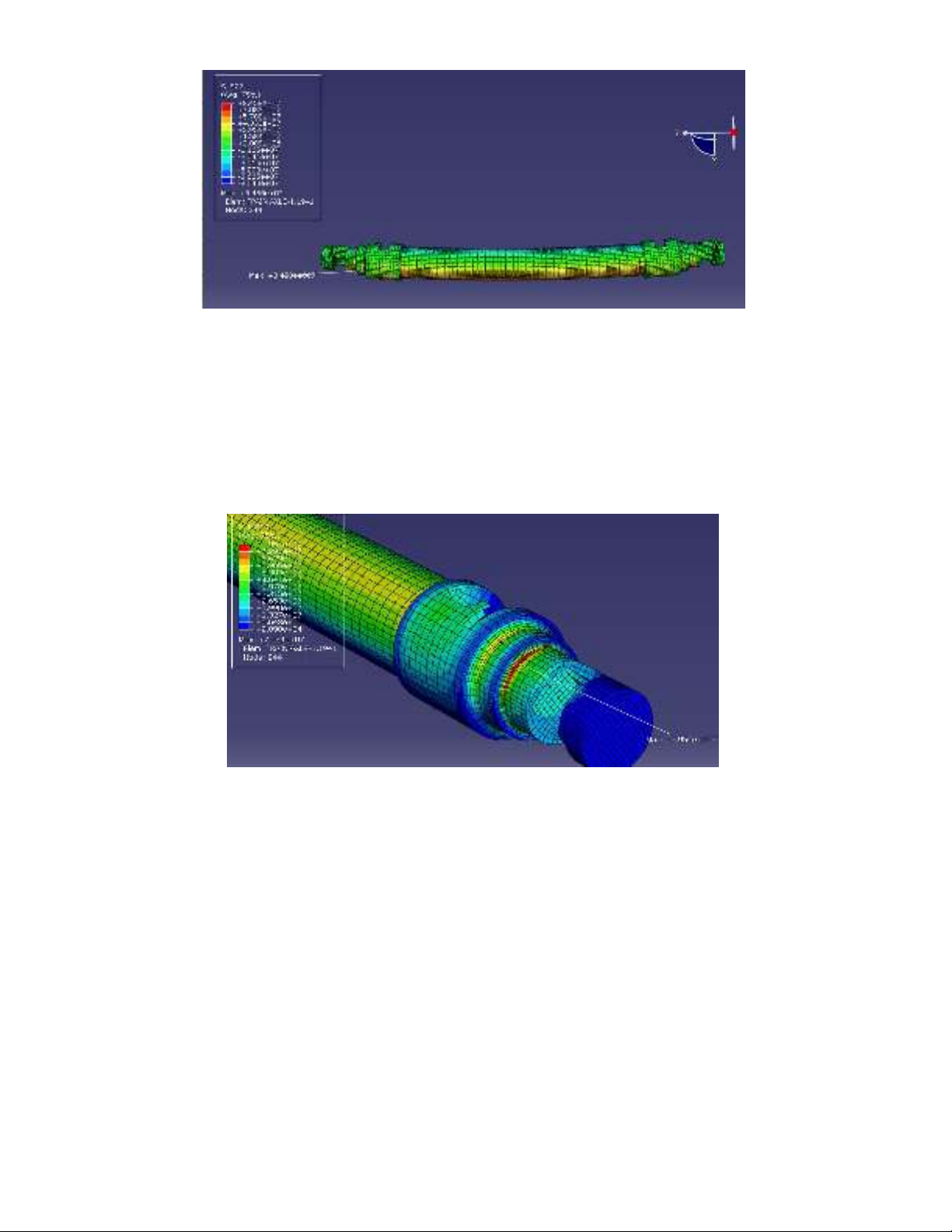
The model was meshed; the loading and boundary conditions were applied and the finite element
linear elastic stress analysis was performed by using the commercial code ABAQUS. A total number
of 40000 quadratic elements were used in the model. A large number of elements were utilized in the
vicinity of fillets because of existing high stress gradients. Figs. 3 and 4 reveal the meshed axle after
loading and the longitudinal stress distribution in the axle, respectively.
Fig. 3. The meshed axle after loading
30
Fig. 4. The longitudinal stress distribution in the axle
Note that the locations of the applied loads and also the bearing positions are locally removed after
analysis to avoid misunderstanding about the position of the maximum stress (those locations
experience high local stresses due to concentrated loads applied). Fig. 5 shows clearly that the
maximum Von-Mises stress of about 80 MPa occurs on the shaft surface at the first fillet near to the
bearings location. Since the dominant stress component in the shaft is longitudinal (due to bending),
the maximum values of the longitudinal and Von-Mises stresses are very close together (about 84 and
80 MPa, respectively).
Fig. 5. Von-Misses stress distribution in the axle
A comparison of the value of maximum Von-Mises stress with the material yield strength (presented
in Table 2) revealed that the material strength is four times larger than the maximum stress
demonstrating no plastic deformation in the axle.In the next section, the stress distribution obtained
above is utilized to compute the stress intensity factors (SIFs) for several defects located in different
positions at the critical cross-section of axle and to determine the allowable size for them.
4. Determination of permissible defects size
4.1. Part-through semi-circular crack
The international railway standard UIC 811-1 (1983) prescribes permissible defects size of maximum
3 mm in production of road axles. The UIC prescription is not clear enough for considering the
influence of cracks at the critical region of the railway axle. Also, it is not stated in this standard that
the permissible size is for what kinds of cracks (e.g. part-through or through etc.). Therefore, first, a
part-through semi-circular surface crack of 3 mm radius was modeled in the shaft at its critical
section and the maximum stress intensity factors (SIFs) were computed by using the finite element
A.R. Torabi and M.R.M. Aliha / Engineering Solid Mechanics 1 (2013)
31
(FE) method under the applied load. Finally, comparing the SIFs with the value of the fatigue crack
propagation threshold of the material gave rise to judge preliminarily about the possibility of growing
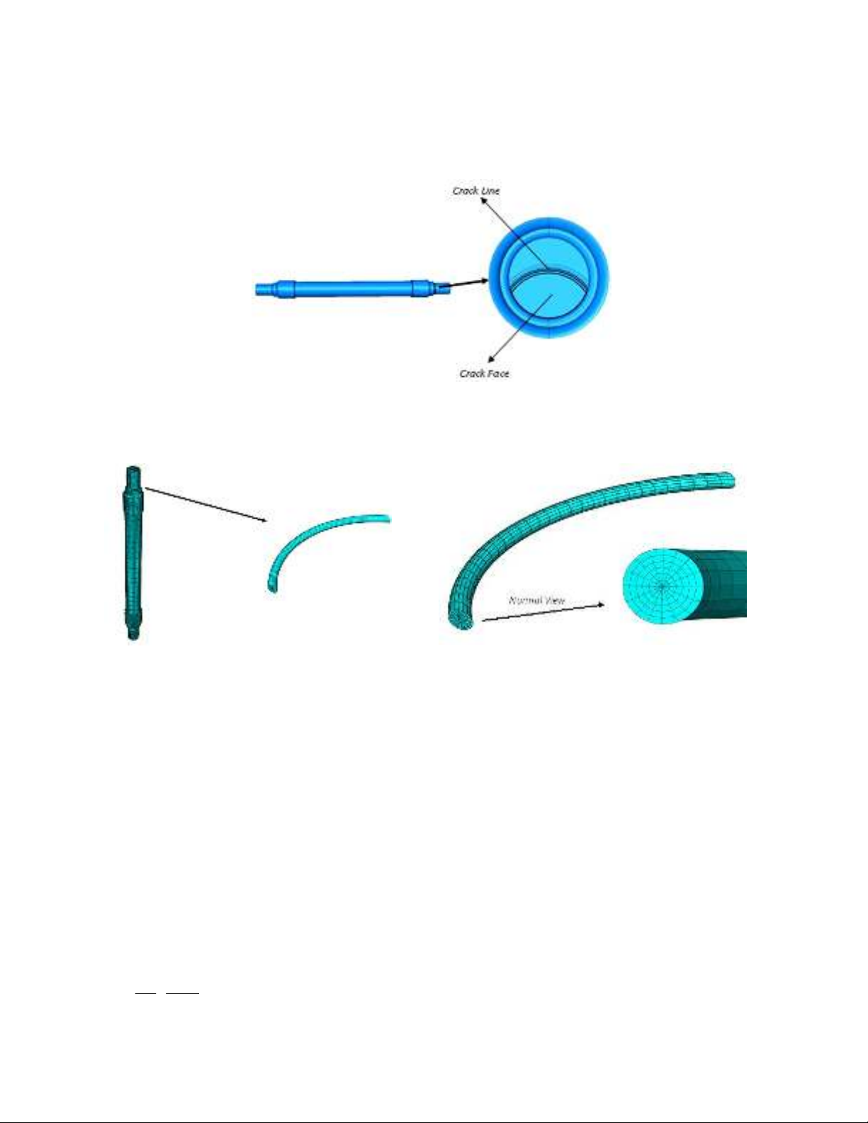
the defect as elaborated below. Fig. 6 shows the cross-section of the axle at its critical region (i.e. the
location of the maximum stress) containing several semi-circular surface defects of different radii
modeled in the FE software.
Fig. 6. The axle critical cross-section containing several semi-circular surface defects of different radii
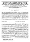
To compute the SIFs more accurately, a large number of elements were created at the vicinity of the
crack front because of high stress gradient. Fig. 7 depicts a mesh pattern around the crack front.
(a)
(b)
Fig. 7. A FE mesh pattern around the crack front
The modes I, II and III SIFs (i.e. KI, KII and KIII) were calculated for the modeled crack (i.e. the crack
with 3 mm radius) using the fracture toolbox of ABAQUS. It was found that KIII was zero and KII was
about 6% of KI demonstrating mode I dominant loading conditions. Thus, the contribution of mode II
crack deformation was neglected and the loading was assumed to be pure mode I (this assumption is
illustratively demonstrated in the section 5 of the present paper for a broken defective axle). The
value of KI for the crack was obtained to be approximately equal to 6.15 MPa m0.5. This value is
almost the same with the value of the fatigue crack propagation threshold (∆Kth) of the C35 steel
reported by Iran railway research center (2000) to be equal to 6 MPa m0.5. Note that ∆Kth value
presented in this report has been determined by conducting the standard fatigue crack growth test
according to the ASTM E647-95 (1995). Consequently, the crack radii larger than about 3 mm will
result in ∆KI > ∆Kth and hence, the defect may propagate under fatigue loading. In addition to ∆Kth,
another important factor which is required to evaluate the growth of initial defects under mode I
loading conditions is the value of tensile stress at the critical distance rc from the crack front. rc is
determined from the following equation suggested by El Haddad et al. (1979)::
2
2
1
e
th
cS
K
r
(1)


![Giáo trình Solidworks nâng cao: Phần nâng cao [Full]](https://cdn.tailieu.vn/images/document/thumbnail/2026/20260128/cristianoronaldo02/135x160/62821769594561.jpg)


![Giáo trình Vật liệu cơ khí [mới nhất]](https://cdn.tailieu.vn/images/document/thumbnail/2025/20250909/oursky06/135x160/39741768921429.jpg)
