CÔNG NGHỆ https://jst-haui.vn Tạp chí Khoa học và Công nghệ Trường Đại học Công nghiệp Hà Nội Tập 60 - Số 8 (8/2024)
68
KHOA H
ỌC
P
-
ISSN 1859
-
3585
E
-
ISSN 2615
-
961
9
EFFECT OF ECAP ROUTES ON STRAIN TO M1 COPPER PLATE
ẢNH HƯỞNG CỦA CÁC LỘ TRÌNH ECAP ĐẾN BIẾN DẠNG ĐỐI VỚI PHÔI DẠNG TẤM DÀY VẬT LIỆU ĐỒNG M1 Dao Manh Anh Tuan1,*, Ta Dinh Xuan1, Nguyen Thanh Hung1 DOI: http://doi.org/10.57001/huih5804.2024.266 1. INTRODUCTION In recent years, UFG materials have become known as critical materials in aerospace, manufacturing, and other sectors due to their exceptional mechanical and physical characteristics. UFG metal is considerably more durable than conventional materials, enabling the construction of significantly lighter structures. The most feasible method for producing UFG metal is severe plastic deformation (SPD), which subjects it to considerable accumulated strain without substantially altering its original shape and size [1]. Several methods of SPD, including high-pressure torsion (HPT), cyclic extrusion compression (CEC), and equal channel angular pressing (ECAP),… can be used to manufacture ultrafine-grained (UFG) materials for metals and alloys. The high-pressure torsion (HPT) method allows for achieving highly high strains without causing significant damage to the sample or tool. Nevertheless, this technique is limited to compact workpieces and exhibits non-uniform deformation directly proportional to the radius [2]. The cyclic extrusion compression (CEC) method can create high hydrostatic pressure, letting the material deform plastically while maintaining its shape [3, 4]. However, the equipment required to conduct this procedure is highly complex since controlling the back pressure to shape the workpiece along the die cavity is difficult. Therefore, this research suggests using the equal channel angular pressing (ECAP) method to investigate the ultrafine-grained (UFG) material manufacturing process. This approach has gained widespread use and popularity,
ABSTRACT
This study utilizes 3D simulations to assess the influence of four different ECAP
routes on the mean strain and
strain homogeneity on the M1 copper plate.
After six
passes, the simulation results significantly improved the mean strain and strain
homogeneity. The mean plastic strain increases significantly when applied along route
BC, while it decreases most
along route A. The strain homogeneity is best when used
along route A and poor when applied along route C throughout the entire volume.
However, when examining a cross
-
section 20mm away from the sample head, which
represents the features in the center of t
he sample, it is clear that applying through
route C leads to a greater degree of uniform deformation than routes B
A and BC
. The
results showed that route A is suitable for pressing when the entire material is required.
However, routes B
A and BC are utiliz
ed when a significant mean strain is desired and
only a uniform material section is used.
Keywords: ECAP process, ECAP routes, copper M1, 3D simulation, strain homogeneity.
TÓM T
ẮT Nghiên cứu này sử dụng mô phỏng 3D để đánh giá ảnh hưởng của các 4 lộ
trình ép
qua kênh g
ấp khúc tới biến dạng và sự đồng đều biến dạng đối với phôi dạng tấm d
ày
v
ật liệu đồng M1. Kết quả mô phỏng cho thấy sau 6 lần ép, biến dạng trung bình và đ
ộ
đ
ồng đều biến dạng đều cải thiện lên đáng kể. Biến dạng trung bình tăng cao nhấ
t khi
ép qua l
ộ trình Bc và thấp nhất khi ép qua lộ trình A còn đ
ộ đồng đều biến dạng tốt nhất
v
ới lộ trình A và kém nhất là lộ trình C trên toàn bộ thể tích. Tuy nhiên, khi xét t
ại mặt
c
ắt ngang cách đầu phôi 20 mm đại diện cho tính chất ở trung tâm phôi cho th
ấy, khi
ép qua l
ộ trình C cho mức độ đồng đều biến dạng tốt hơn lộ trình BA và BC. K
ết quả cho
th
ấy, lộ trình A phù hợp khi yêu cầu sử dụng toàn bộ vật liệu sau khi ép còn lộ trình BA
,
B
C được sử dụng khi yêu cầu biến dạng trung bình lớn và ch
ỉ cần sử dụng một phần đồng
nh
ất của vật liệu. Từ khóa: ECAP, lộ trình ECAP, đồng M1, mô phỏng 3 chiều, đồng đều biến dạng.
1
Faculty of Mechanical Engineering, Le Quy Don Technical University, Vietnam
*
Email: tuandaogcal@gmail.com
Received: 10/5/2024
Revised: 18/6/2024
Accepted:
27/8/2024

P-ISSN 1859-3585 E-ISSN 2615-9619 https://jst-haui.vn SCIENCE - TECHNOLOGY Vol. 60 - No. 8 (Aug 2024) HaUI Journal of Science and Technology 69
facilitating handling of large workpieces with relatively simple equipment. The principle of the ECAP technique involves pressing the workpiece through a die having two channels intersecting at a fixed angle of Φ and the outer corner of ψ (Fig. 1a) without changing the original cross-sectional area of the workpiece. It is also possible to rotate the sample along its longitudinal axis during multiple passes, generating different routes (Fig. 1b) [5]. The equivalent plastic strain value after undergoing N passes is determined by the formula 1 [1]: eqNψψε2cotψcosec223
(1) During the ECAP procedure, workpieces can undergo different routes by being axially rotated after each pressing. Fig. 1b displays four ECAP processing routes that have been found based on the rotation of the sample [6]. (a) (b) Fig. 1. Concept of ECAP (a) and four basis ECAP routes (b) Different ECAP routes can lead to distinct strain levels, grain microstructures, and technical characteristics. Recently, many researchers have examined various issues when investigating the impact of ECAP routes. Abhishek Ghosh et al. [7] employed the finite element method to analyze the deformation of a bar-shaped AL-Zn-Mg-Cu alloy after applying the ECAP process through three different routes: A, BC, and C. The simulation findings indicate that the most optimal outcomes are achieved using the BC route. Mohamed Osman et al. [8] utilized Deform 3D software to simulate the deformation process of Ti-50.8% Ni bar billets along the BC route. The findings indicate an increase in the cumulative average strain and the formation of an ultrafine-grained (UFG) structure. However, inhomogeneity is still present across the planes. Mohamed Ibrahim [9] conducted simulations to examine the efficacy of ECAP, extrusion, and combined ECAP-extrusion procedures in creating UFG-structured composites using Al-1080 materials. The numerical simulation results match the experimental findings, indicating that the workpiece produced utilizing the ECAP approach achieves the highest level of uniform deformation. The research mentioned above concentrated on the assessment of strain for bar workpieces with square or circular cross-sections. The best strain, according to these findings, is obtained while pressing along the BC route. However, there have been several research on plate blanks, which are used for producing sheet products. This study focuses on the ECAP method applied to the four main routes of the copper M1 plate, which is extensively utilized in the manufacturing, aerospace, and military industries. The Qform software simulates and assesses the deformation characteristics and uniformity of plastic strain in M1 copper. This provides the foundation for evaluating the potential to achieve ultra-fine grain structures using the ECAP method. 2. FINITE ELEMENT METHOD 2.1. Simulation model The simulation model includes a punch, die, and workpiece with angle Ф = 90º, ψ = 0º, as shown in Fig. 2a. The study utilized M1 copper, which is considered isotropic. The composition of M1 copper is detailed in Table 1 [10], while the stress-strain relationship at a temperature of 20°C was obtained from the Qform library, as shown in Fig. 2b. The workpiece utilized in the research method is a rectangular plate with dimensions of 50 x 50 x 10mm. (a) (b) Fig. 2. Stress-strain relationship of M1 copper at 20°C (a) and 3D modelling (b) During the simulation, the friction coefficient (µ) between the workpiece and the tools, as well as the velocity of the punch (v = 15mm/s), were maintained at a constant value. In addition, the potential for heat rise in the workpiece and heat transfer with the tools were considered. The material used for the tool is X12MΦ, which was established in the software and had a hardness of 59 HRC at a temperature of 20°C. The workpiece undergoes

CÔNG NGHỆ https://jst-haui.vn Tạp chí Khoa học và Công nghệ Trường Đại học Công nghiệp Hà Nội Tập 60 - Số 8 (8/2024)
70
KHOA H
ỌC
P
-
ISSN 1859
-
3585
E
-
ISSN 2615
-
961
9
six passes in four routes, as depicted in Fig. 2b. Because of the rise in temperature during the deformation process, it is necessary to cool the workpiece back to its original temperature after each pass before proceeding with further pressing. In the actual process, a portion of the workpiece must be lost because, after each pressing, a piece of the length has to be cut off, and burrs have to be ground away. Table 1. Chemical composition of copper M1 Chemical element Cu Fe Zn O Content, % 99.94 0.005 0.004 0.051 2.2. Assessment method Fig. 3 illustrates the sample following the initial ECAP pass. The unequal distribution of plastic strain is evident, particularly at the head and end of the workpiece. Hence, in addition to considering the deformation and distribution across the entire workpiece, it is necessary to evaluate the distribution in both the head and center areas. To assess the strain distribution uniformity, choose two cross-sections, A and B, positioned approximately 5mm and 20mm away from the head of the workpiece, as indicated in Fig. 3. These cross-sections will represent the deformation at the ends and middle of the workpiece, respectively. Fig. 3. Plastic strain after the first ECAP pressing To assess the uniformity of strain distribution, utilize the inhomogeneity index (Ci) [7, 11, 12]:
maxminiavg
εεCε
(2) εmax, εmin, and εavg denote the plastic strain's maximum, minimum, and mean, respectively. A smaller value of this index indicates a higher level of uniformity in strain distribution. 3. RESULT AND DISCUSSION Fig. 4 illustrates the relationship between force and displacement during the initial pressing. During the initial stage, the force undergoes a rapid promotion, reaching at around 3 - 5mm from the beginning of the stroke. And then, the force diminishes in a straight line because the area of contact between the workpiece and the die reduces as more material escapes through the outlet channel. The maximum value achieved is about 33 tons, suitable for most hydraulic presses used in laboratories. Fig. 5 illustrates the simulation results obtained after six pressing passes following four routes. Due to the mechanical machining, a workpiece section is removed after each pass, so the sample is changed from its original square to a rectangular one. Following routes BA and BC, the workpiece undergoes a 90º rotation after each pressing. Because the shape of the workpiece is changed to rectangular, when pushing through the BC and BA routes, the workpiece performs the upsetting process in the inlet channel to reach the width size first and then passes through the outlet channel. As a result, the product will have an irregular shape when pressed using these two routes compared to routes A and C. The finished product must eliminate significant material to achieve a uniform shape. Fig. 4. Plastic strain of the workpieces after six passes (a) Route A (b) Route BA

P-ISSN 1859-3585 E-ISSN 2615-9619 https://jst-haui.vn SCIENCE - TECHNOLOGY Vol. 60 - No. 8 (Aug 2024) HaUI Journal of Science and Technology 71
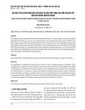
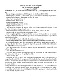
(c) Route BC (d) Route C Fig. 5. Plastic strain of the workpieces after six passes Fig. 6 illustrates the mean plastic strain on the workpiece and the inhomogeneity index during the pressing process across four different routes. The mean strain values are compared with those obtained after calculating theoretical formula 1. The mean plastic strain obtained after six passes varied between 6.4 and 7.5. This value is within the range for severe plastic deformation (6-8) [13]. The graph in Figure 6a demonstrates that the results obtained from simulation calculations exhibit a significant degree of closeness to the theoretical formula 1. After six pressing passes, the mean strain value exhibited a linear increase, and there was a considerable improvement in homogeneity across all four routes. The mean strain value increases in the following order: route A, route C, route BA, and finally, route BC. When assessing the uniformity throughout the total volume of the workpiece, route A shows the highest level of uniformity, followed by routes BA, BC, and finally, route C. When examining the total volume of the workpiece, it is evident that the 90º rotation routes (BA, BC) result in a higher degree of accumulated strain and a moderate level of homogeneity. The graphs in Figs. 6b and 7a demonstrate that the inhomogeneity index over the entire volume and at cross-section A is similar across all four routes. Therefore, the level of uniformity at the initial and final positions of the workpiece significantly impacts the level of uniformity in deformation throughout the entire volume of the workpiece. In cross-section B (Fig. 7b), which is 20mm from the end face, representing the middle of the sample, route A still gives the best level of deformation uniformity. This is followed by route C, then route BA, and finally route BC. In contrast to the mean plastic strain value, the 90º rotation pressing methods result in less homogeneous deformation in the middle of the workpiece than the other two routes. Route C has better strain uniformity in the center area of the workpiece when compared to routes BA and BC. However, it has lower mean plastic strain and uniformity strain across the entire volume than the other routes. (a) (b) Fig. 6. Mean of plastic strain (a) and inhomogeneity index (b) over the entire workpiece (a)

CÔNG NGHỆ https://jst-haui.vn Tạp chí Khoa học và Công nghệ Trường Đại học Công nghiệp Hà Nội Tập 60 - Số 8 (8/2024)
72
KHOA H
ỌC
P
-
ISSN 1859
-
3585
E
-
ISSN 2615
-
961
9
(b) Fig. 7. Inhomogeneity index at cross-section A (a) and cross-section B (b) 4. CONCLUSION This study has demonstrated the plastic deformation and its distribution during the ECAP process of the M1 copper plate using four routes. The pressing route selection depends on the purpose and specifications of the pressing process, as shown by the results mentioned above. Route A provides excellent strain uniformity throughout the sample, particularly at the beginning and middle, but the cumulative strain level is the lowest. When conducting ECAP along route C, the uniformity of strain in the middle of the workpiece is very good. However, the overall workpiece exhibits the lowest level of strain uniformity, and the accumulated strain is also relatively low. Though the uniformity is average, routes BC and BA have a high mean plastic strain. Furthermore, a portion of the material needs to be removed following the ECAP process due to the unequal and distorted shape of the workpiece at the head. Therefore, route A is recommended if the requirement for uniformity is well met and the mean strain value does not need to be too high. If a significant amount of strain is required and the level of homogeneity is not a primary concern, the options to consider are either BA or BC. REFERENCES [1]. A.Rosochowski, Severe plastic deformation technology. Scotland, UK: Whittles Publishing, 2017. [2]. A. P. Zhilyaev, T. G. Langdon, “Using high-pressure torsion for metal processing: Fundamentals and applications,” Prog. Mater. Sci., 53, 6, 893-979, 2008. doi: 10.1016/j.pmatsci.2008.03.002. [3]. A. Rosochowski, “Processing metals by severe plastic deformation,” Solid State Phenom., 101-102, 13-22, 2005. doi: 10.4028/www.scientific.net/ssp.101-102.13. [4]. R. Lapovok, “The Positive Role of Back-Pressure in Equal Channel Angular Extrusion,” Mater. Sci. Forum, 503-504, 37-44, 2006. doi: 10.4028/www.scientific.net/msf.503-504.37. [5]. V. V Stolyarov, Y. T. Zhu, I. V Alexandrov, T. C. Lowe, R. Z. Valiev, “Influence of ECAP routes on the microstructure and properties of pure Ti,” Materials Science and Engineering: A, 299, 1-2, 59-67, 2001. [6]. K. Hajizadeh, H. Farhad, K. J. Kurzydlowski, “Effect of ECAP processing routes on the microstructural characteristics of commercial purity titanium,” Appl. Phys. A, 129, 8, 583, 2023. doi: 10.1007/s00339-023-06868-8. [7]. A. Ghosh, M. Ghosh, “3D FEM simulation of Al-Zn-Mg-Cu alloy during multi-pass ECAP with varying processing routes,” Mater. Today Commun., 26, no. February, 102112, 2021. doi: 10.1016/j.mtcomm.2021.102112. [8]. M. Osman, D. T. Zhang, Y. X. Tong, Y. F. Zheng, L. Li, “3D FEM simulation of multipass ECAP Ti-50.8%Ni at various temperatures,” Adv. Mater. Res., 1004-1005, 1204-1210, 2014. doi: 10.4028/www.scientific.net/AMR.1004-1005.1204. [9]. M. I. Abd EL AAL, “3D FEM simulations and experimental validation of plastic deformation of pure aluminum deformed by ECAP and combination of ECAP and direct extrusion,” Trans. Nonferrous Met. Soc. China (English Ed.), 27, 6, 1338-1352, 2017. doi: 10.1016/S1003-6326(17)60155-9. [10]. S. Lezhnev, I. Volokitina, T. Koinov, “Research of influence equal channel angular pressing on the microstructure of copper,” J. Chem. Technol. Metall., 49, 6, 621-630, 2014. [11]. S. Li, M. A. M. Bourke, I. J. Beyerlein, D. J. Alexander, B. Clausen, “Finite element analysis of the plastic deformation zone and working load in equal channel angular extrusion,” Mater. Sci. Eng. A, 382, 1-2, 217-236, 2004. doi: 10.1016/j.msea.2004.04.067. [12]. F. Djavanroodi, B. Omranpour, M. Ebrahimi, M. Sedighi, “Designing of ECAP parameters based on strain distribution uniformity,” Prog. Nat. Sci. Mater. Int., 22, 5, 452-460, 2012. doi: 10.1016/j.pnsc.2012.08.001. [13]. R. Valiev, “Nanostructuring of metallic materials by SPD processing for advanced properties,” Int. J. Mater. Res., 100, 6, 757-761, 2009. doi: 10.3139/146.110095. THÔNG TIN TÁC GIẢ Đào Mạnh Anh Tuấn, Tạ Đình Xuân, Nguyễn Thanh Hùng Khoa Cơ khí, Trường Đại học kỹ thuật Lê Quý Đôn