
* Corresponding author. Tel/Fax: +98 7433221711
E-mail addresses: m.zamani.n@gmail.com, m_zamani@yu.ac.ir (M. Zamani Nejad)
© 2015 Growing Science Ltd. All rights reserved.
doi: 10.5267/j.esm.2015.1.003
Engineering Solid Mechanics 3 (2015) 117-130
Contents lists available at GrowingScience
Engineering Solid Mechanics
homepage: www.GrowingScience.com/esm
An elastic analysis for thick cylindrical pressure vessels with variable thickness
Mehdi Ghannada, Mehdi Jabbarib and Mohammad Zamani Nejadb*
aMechanical Mechanical Engineering Faculty, Shahrood University, Shahrood, Iran
bMechanical Engineering Department, Yasouj University, Yasouj, Iran
A R T I C L E I N F O A B S T R A C T
Article history:
Received October 6, 2014
Accepted 28 January 2015
Available online
29 January 2015
This paper derives
a
semi
-
analytical solution
to
determin
e
displacements and stresses in a thick
cylindrical shell with variable thickness under uniform pressure based on disk form
multilayers. The proposed study partitions the thick cylinder into disk-layer parts based on their
thickness of the cylinder. According to the existence of shear stress in the thick cylindrical
shell with variable thickness, the equations governing disk layers are acquired based on first
shear deformation theory (FSDT), which are in the form of a set of general differential
equations. In this study, the cylinder is partitioned into n different disks and n sets of differential
equations are derived. The solution of these equations provides displacements and stresses
based on the boundary conditions and continuity conditions between the layers. The results are
compared with those obtained through the analytical solution and the numerical solution. For
the purpose of the analytical solution, matched asymptotic method (MAM) and for the
analytical solution, the finite element method (FEM are implemented.
© 2015 Growing Science Ltd. All rights reserved.
Keywords:
Thick cylindrical shell with
variable thickness
Disk form multilayers
Matched asymptotic method
Finite element method
1. Introduction
Thick cylindrical shells with variable thickness have extensively been used in various fields such
as space flight, aviation, rocket and submarine technology. Given the limitations of the classic theories
of thick wall shells, there has been few works associated with the analytical and semi-analytical
solutions of these shells (Talaee et al., 2014). Naghdi and Cooper (1956) formulated the theory of shear
deformation by considering the transverse shear effect. Mirsky and Hermann (1956) investigated the
solution of thick cylindrical shells of homogenous and isotropic materials, using the first-order shear
deformation theory (FSDT). Greenspon (1960) compared between the findings regarding various
solutions obtained for cylindrical shells. Vekua (1965) built a refined theory for shallow shells with
variable thickness. Suzuki et al. (1981) studied the axisymmetric vibrations of a cylindrical shell where
the thickness differs in the axial direction by using the thin cylindrical shell theory and an improved
118
thick cylindrical shell theory by applying a series solution. Kang and Leissa (2001) performed an
investigation where equations of motion and energy functional were derived for a three-dimensional
coordinate system. The field equations were utilized to express them in terms of displacement
components. Eipakchi et al. (2003) implemented the FSDT in order to find governing equations of thick
cylinders with varying thickness and analyzed the equations based on perturbation theory. Using tensor
analysis, a complete 3-D set of field equations was proposed for elastic analysis of thick shells of
revolution with arbitrary curvature and variable thickness along the meridional direction made of
functionally graded materials by Nejad et al. (2009). Ghannad et al. (2009) proposed to use the FSDT
analytical solution for homogeneous and isotropic truncated thick conical shell. Ghannad and Nejad
(2010) calculated the differential equations governing the homogenous and isotropic axisymmetric
thick-walled cylinders with same boundary conditions at the two ends, based on the first-order shear
deformation theory and the virtual work principle. In addition, they also solved the set of non-
homogenous linear differential equations for the cylinder with clamped-clamped ends. Finally,
Ghannad et al. (2012) presented an analytical solution for clamped-clamped thick cylindrical shells
with variable thickness by considering constant internal pressure. In this paper, elastic analysis is
presented for pressurized thick cylindrical shells with variable thickness using disk form multilayers.
2. Formulation of problem
According to the first-order shear deformation theory, the parts, which are straight and perpendicular
to the mid-plane stay straight but not always perpendicular after deformation and loading. In such
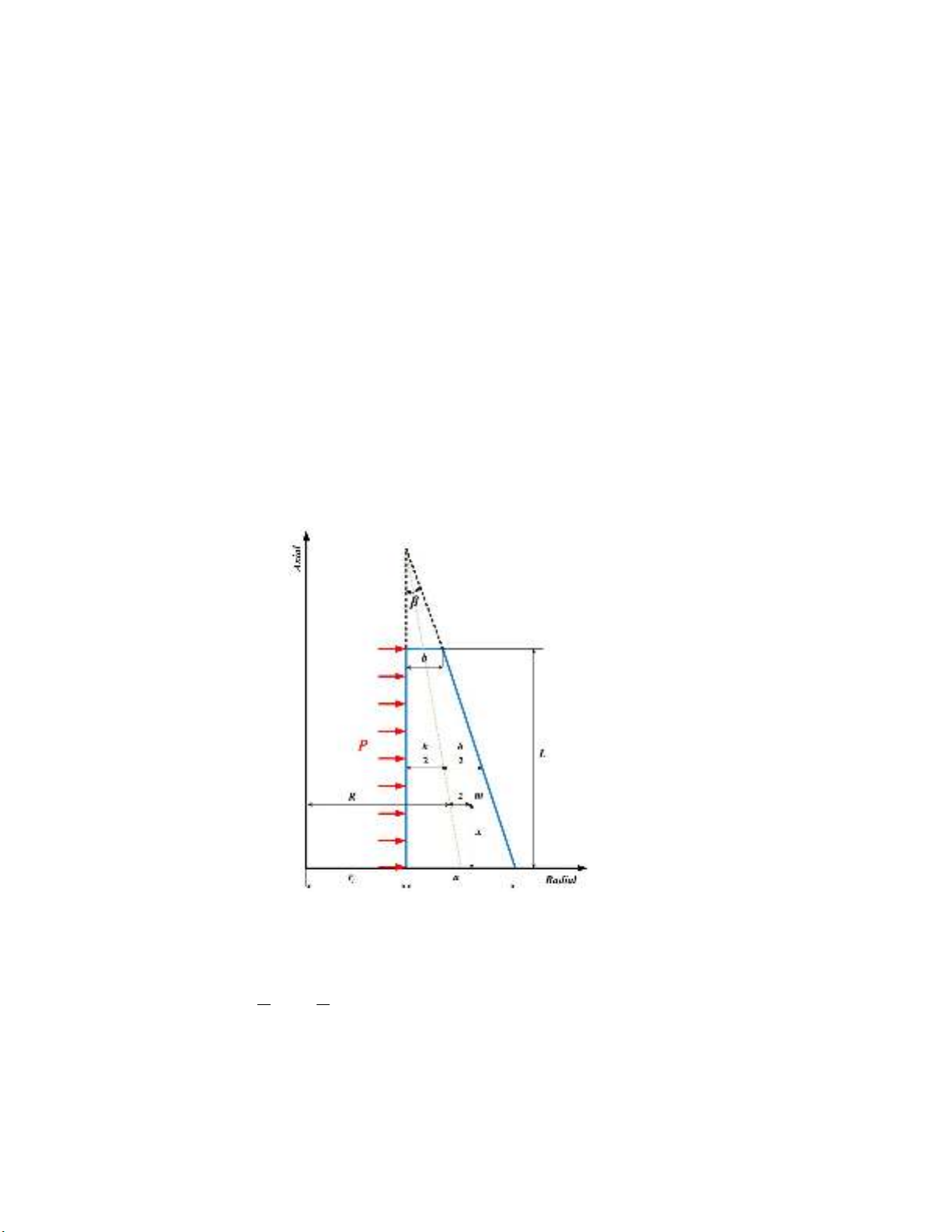
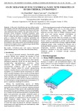
circumstances, shear strain and shear stress are considered. Fig. 1 shows geometry of a thick cylindrical
shell where
h
and L represent variable thickness and length, respectively.
Fig. 1. Thick cylindrical shell with variable thickness
The location of a typical point
m
, within the shell element is as follows,
: , ,
0 &
2 2
-
m r x R z x
h h
x L z
(1)
where
z
is the distance of typical point from the middle surface. In Eq. (1),
R
and variable thickness
h
are
M. Ghannad et al. / Engineering Solid Mechanics 3 (2015)
119
1tan
2 2
tan
i
i
a
R x r x
h x r a x
(2)
where
is tapering angle as
1
tan
a b
L
(3)
The general axisymmetric displacement field
,
x z
U U
, in the first-order Mirsky-Hermann's theory
(1956) could be stated on the basis of axial displacement and radial displacement, as follows,
, ( ) ( )
, ( ) ( )
x
z
U x z u x x z
U x z w x x z
(4)
where
( )
u x
and
( )
w x
are the displacement components of the middle surface. Also,
( )
x
and
( )
x
are the functions applied to determine the displacement field. The kinematic equations (strain-
displacement relations) in the cylindrical coordinates system are
x
x
z
z
z
x z
xz
U du d z
x dx dx
U w z
r R z R z
U
z
U U d
dw
z
z x dx
dx
(5)
The stress-strain relations (constitutive equations) for homogeneous and isotropic materials are as
follows,
1 0
1 0
1 0
1 2
0 0 0 2
x x
z z
xz xz
(6)
where
i
and
i
,
, ,
i x z
are the stresses and strains in the axial
x
, circumferential
, and
radial
z
directions.
and
E
are Poisson’s ratio and modulus of elasticity, respectively. In Eqs. (6),
is
1 1 2
E
. (7)
The normal forces (
, ,
x z
N N N
), bending moments (
, ,
x z
M M M
), shear force (
x
Q
), and the
torsional moment (
xz
M
) in terms of stress resultants are

120
2
2
1
1
x
xh
h
z
z
z
NR
dz
N
Nz
R
(8)
2
2
1
1
x
xh
h
z
z
z
MR
M
zdz
Mz
R
(9)
2
2
1
h
x xz
h
z
Q K dz
R
(10)
2
2
1
h
xz xz
h
z
M K zdz
R
(11)
where
K
is the shear correction factor that is embedded in the shear stress term. In the static state,
5 6
Kfor cylindrical shells (Vlachoutsis, 1992). On the basis of the principle of virtual work, the
variations of strain energy are equal to the variations of work of external forces as follows;
U W
, (12)
where
U
is the total strain energy of the elastic body and
W
is the total work of external forces due to
internal pressure
P
. With substituting strain energy and work of external forces, we have,
/2
0 /2 0 2
1
L h L
z
h
x x z z xz xz
h
R P U dx
R
zdzdx
xR
. (13)
Substituting Eqs. (5) and (6) into Eq. (13), and drawing upon calculus of variation and the virtual
work principle, we will have,
0
0
2
2
2
x
x
xx
x
x
xz
xz z
N R C
dR dM
M R Q
dx dx
dQdR h
Q R N P R
dx dx
dR h
dM
h
M R M P
NR
dx dx
(14)
and the boundary conditions are
0
0
L
x x x xz R
N u M Q w M
. (15)
Eq. (15) states the boundary conditions which must exist at the two ends of the cylinder. In order to
solve the set of differential equations (14), with using of Eqs. (5) to (11), and then using Eq. (14), we
have
M. Ghannad et al. / Engineering Solid Mechanics 3 (2015)
121
2
31 2
2
T
d d BB B
y y y
F
dx dx
du dx wy
(16)
The coefficients matrices
4 4
i
B
, and force vector
4 1
F
are as follows,
3
3
1
3 3
0 0 0 0
0 1 0 0
12
0 0 12
0 0 12 12
hR
Bh
hR
h h
R
(17)
3
3 2 3
22
3 2 2
0 1 0 0
12
1 1 3 2
12 12 12
04
0 2 3
12 4 12
h
h h dh dR h
R h hR
dx dx
Bdh dR h dh
hR R h
dx dx dx
h h dh h dh dR
R h
dx dx dx
(18)
2 2
3
2
2
0
1
1 0
4 2
1 1
1 1
4
hR h hR
h dh h dh
hR
dx dx
Bdh dR
h R h h R
dx dx
h dh
hR h R R
dx
(19)
0
0
1
2
2
2
C
h
P
F R
h
h
PR
(20)
where the parameters are as follows,
51 2
12
2
ln
2
R h
R h
(21)


![Bài tập tối ưu trong gia công cắt gọt [kèm lời giải chi tiết]](https://cdn.tailieu.vn/images/document/thumbnail/2025/20251129/dinhd8055/135x160/26351764558606.jpg)