
* Corresponding author.
E-mail addresses: mirmilad@tamu.edu (M. M. Mirsayar)
© 2017 Growing Science Ltd. All rights reserved.
doi: 10.5267/j.esm.2017.8.001
Engineering Solid Mechanics (2017) 293-306
Contents lists available at GrowingScience
Engineering Solid Mechanics
homepage: www.GrowingScience.com/esm
Evaluation of interfacial bond strength between Portland cement concrete and
asphalt concrete layers using bi-material SCB test specimen
M. M. Mirsayara*, X. Shia and D. G. Zollingera
aTexas A&M University, Zachry Department of Civil Engineering, College Station, TX 77843-313, USA
A R T I C L EI N F O A B S T R A C T
Article history:
Received 6 April, 2017
Accepted 3 August 2017
Available online
3 August 2017
Portland cement concrete (PCC) / asphalt concrete (AC) bonded components are seen in both
conventional pavement structures as well as overlays. Due to the environmental and traffic
loads, cracks occur at the interface of the PCC and AC layers and finally, may propagate
through the interface or one of the layers. Therefore, the evaluation of bond strength between
these layers is important. This paper investigates bond strength between asphalt concrete and
Portland cement concrete using a new sandwich test specimen. The developed specimen, called
Bi-material semi-circular bend (BSCB) is made of asphalt concrete and the Portland cement
concrete, cracked at the interface of the materials. First, the suggested specimen is introduced
and characterized using finite element simulation. Then, the specimen is employed to obtain
bond strength between asphalt concrete and Portland cement concrete under mixed mode
loading, and at two temperatures: -20C and 20C. The fracture toughness at different mixed
mode conditions is obtained, and finally, fracture criterion for the tested bonded joints is
presented.
© 2017 Growing Science Ltd. All rights reserved.
Keywords:
Bi-material SCB specimen
Interfacial bond strength
Cement/asphalt interface
Experimental study
Fracture theory
1. Introduction
Bonded layers can be seen as a part of many industrial and engineering structures. In pavement
industry, the white topping rehabilitation technique has recently been explored by many U.S.
Departments of Transportation (DOTs) whereby a relatively thin layer of concrete is applied over a
prepared asphalt concrete base. As noted in the literature, an interface crack may occur between the
pavement layers, mainly due to the external environmental induced movements, that propagate and
delaminate the layers. Bonded joints are not limited to the pavement engineering application and are
widely used in other engineering structures. For example, bonding components made of concrete/rock,
silicon/glass, ceramic/metal and composite/metal are extensively used in civil engineering structures,
electronic devices, automobiles and aircrafts (Yang et al., 1998; Chaudhuri & Chiu, 2007; Chandra
Kishen & Singh, 2001; Wang et al., 2013; Dunn et al., 2000). At the interface of all bi-material

294
components, cracks may create as a result of imperfect bonding or during the service life of the
structures containing these bonds. The interface cracks are often subjected to mixed mode loading
conditions, because of the asymmetry in material property at the interface, and they may propagate
through the interface, or may kink into one of the materials in the strong interfaces (e.g. Arabi et al.,
2013; Ayatollahi & Mirsayar, 2011; Ayatollahi et al., 2010a,b; Ayatollahi et al., 2011; Chandra Kishen
& Singh, 2001; Dunn et al., 2000; Mirsayar, 2013, 2014a, b, c; Mirsayar & Park, 2016a; Mirsayar &
Samaei, 2013, 2014, 2015).
Several theoretical and experimental methods have been explained by researchers in the past to
investigate mechanism of crack propagation through different materials (e.g. Ambati et al., 2015;
Ayatollahi et al., 2013; Lazzarin and Zambardi, 2001; Miehe et al., 2015; Maiti & Smith, 1983;
Mirsayar 2015a, b; Mirsayar & Park 2016b; Aliha et al. 2012; Mirlohi & Aliha 2013; Mirsayar et al.
2016a; Mirsayar, 2017; Mirsayar et al. 2017a, b; Sih & Macdonald, 1974). While the experimental
fracture studies on real components are often expensive and difficult, researchers prefer to conduct their
experiments on laboratory specimens. However, appropriate fracture criteria are also required to
correlate the experimental results obtained from the simple laboratory specimens to the fracture event
in cracked structures under their complex service loading conditions (Mirsayar & Takabi, 2016). In
order to validate a fracture criterion, researchers have to conduct a series of fracture tests on appropriate
test materials by using suitable test specimens. For mixed mode fracture tests, a suitable test
configuration should have simple geometry and loading conditions, inexpensive preparation
procedures, convenience of testing set up, and also the ability of addressing both mode I and mode II
failure conditions. Some of the test configurations proposed in the literature investigating mixed mode
I/II fracture are briefly described here. Erdogan & Sih (1963), Williams & Ewing (1972) and Theocaris
(1984) used a rectangular plate containing an inclined center crack subjected to a uniform far field
tension in their mixed mode fracture studies. The symmetric and asymmetrically loaded three or four-
point bend specimens were also employed by researchers for investigating mode I and mixed mode
brittle fracture (Fett et al., 1995; Xeidakis et al., 1996; Suresh et al., 1990, Aliha et al. 2009; Razavi et
al., 2017, Aliha & Bahmani 2017; Bahmani et al. 2017; Heidari-Rarani et al., 2014), Disc type
specimens including the centrally cracked Brazilian disk (BD) specimen, centrally cracked/notched
ring specimen subjected to diametrall compression, edge notch disc bend (ENDB) and the semi-circular
bend (SCB) specimen have been frequently employed for determining the mixed mode fracture
resistance of various engineering materials such as rocks, graphite, concretes and polymers (Awaji &
Sato, 1978; Ayatollahi et al., 2006; Ameri et al. 2012,2016; Razmi & Mirsayar, 2017; Alhasan 2013;
Fakhri et al. 2017, Aliha et al. 2008,2014,2015a,c, 2017, Abd-Elhady 2013; Al-Hdabi et al. 2014;
Dehghany et al. 2017, Bahmani et al. 2017). However, some of these specimens have certain
shortcomings. For example, some of the mixed mode test configurations are able to provide only limited
mode mixities or require complicated loading fixtures.
In a bi-material fracture test specimen, the stress intensity factors are influenced by the mechanical
properties of each material as well as the specimen geometry (e.g. Ayatollahi et al., 2010a, b; Mirsayar,
2014a; Mirsayar et al., 2014; Mirsayar & Park, 2015, Mousavi & Aliha 2016). However, for a
conventional fracture test specimen made of a single material, the specimen can be characterized only
by its geometry. In other words, one should choose a bi-material fracture test specimen based on both
specimen geometry as well as the material properties of each material. Some of the test configurations
proposed in the literature for investigating mixed mode I/II fracture of bonded structures are briefly
described in the following. Charalambides et al. (1989) suggested a new four-point bend specimen for
measuring the fracture resistance of bi-material interfaces. Utilizing a finite element approach, they
characterized their suggested specimen and calculated stress intensity factors at different specimen
geometries and elastic properties. They demonstrated the utility of their specimen by conducting tests
on Al/PMMA bonded joints. However, their suggested specimens were not able to cover all mixed
mode conditions that range between pure mode I and pure mode II. Evans et al. (1989) studied the
interface crack propagation in different bi-material fracture test specimens including Sandwich test
specimens, Peel test specimens, de-cohesion test specimens, and composite cylinder test specimens.
They demonstrated that the choice of test specimen governs the tendency of cracks to either remain at
M. M. Mirsayar et al. / Engineering Solid Mechanics 5 (2017)
295
the interfaces or deviate away, depending on the specimen geometry. However, none of the mentioned
specimens were able to cover all mixed mode conditions.
The specimens of circular or semi-circular shape (SCB) are very suitable for fracture testing on
rock or asphalt materials because they can be easily cored from pavement. However, the SCB specimen
has not been used so far for any bi-material testing to evaluate bond strength. In this paper, a bi-material
SCB (BSCB) test specimen is investigated for fracture test of asphalt concrete (AC) / Portland cement
concrete (PCC) bonded layers. The BSCB specimen is further described along with its capabilities and
advantages by means of finite element analysis. Following this discussion, the BSCB specimen is used
to evaluate tensile, shear, and mixed tensile/shear bond strength between Portland cement concrete and
asphalt concrete.
2. Objective of the research
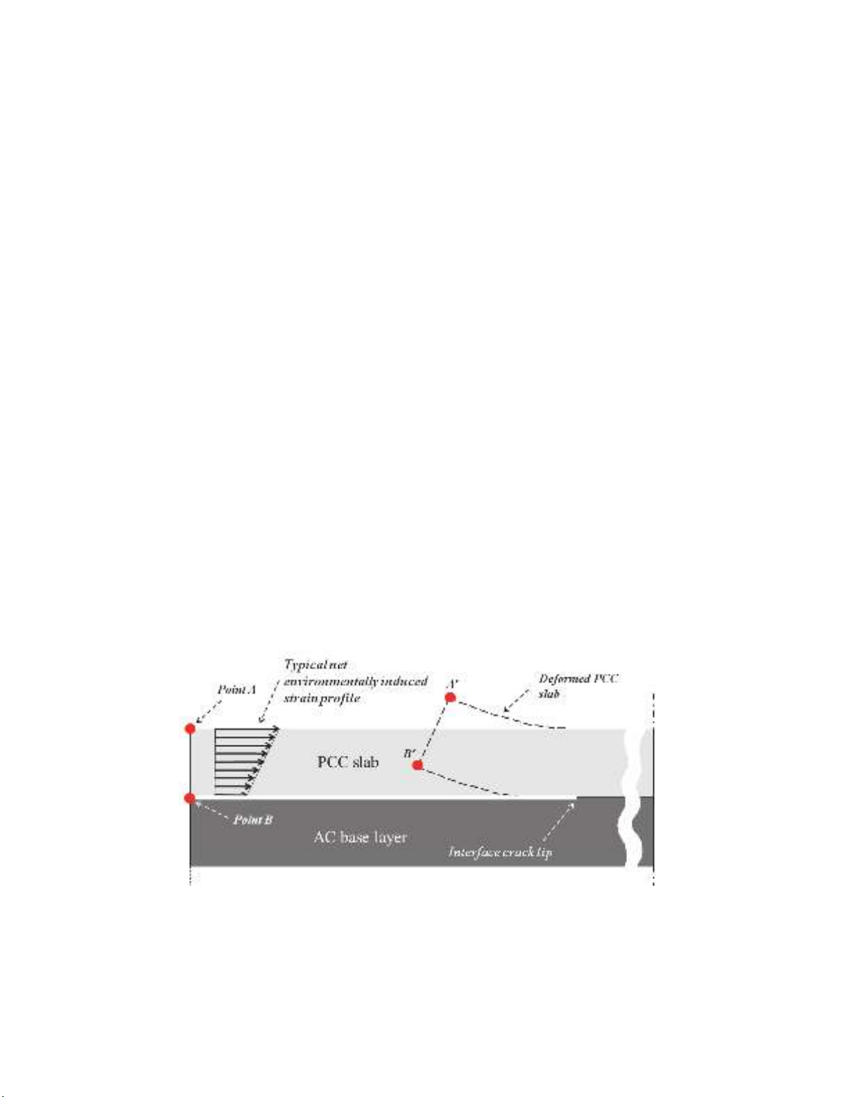
As illustrated in Fig. 1, a concrete slab curls upwards as a result of environmentally induced strain
profile throughout the slab. The end movements in concrete slab, shown in Fig. 1, is the first step
towards erosion damage which is a distress type that threatens the sustainability of a concrete pavement,
and thus, needs to be controlled. The bond strength between the PCC and AC layers significantly
influences on the vertical and horizontal end movements in concrete slab. The slab lift-off is
accompanied by occurring and propagation crack at the interface of two layers, as shown in Fig. 1.
As investigated by Mirsayar et al. (2016b), the interfacial fracture mechanics can be utilized
successfully to describe delamination of the pavement layers. An interface crack can be characterized
by the stress intensity factors. In other words, one can characterize the interfacial bond strength between
the PCC and AC layers by evaluating stress intensity factors of the interface crack. On the other hand,
the critical bond strength is affected by many factors which influence on the chemical bond behavior
between the layers. One of the most important factors is the temperature in which the delamination
occurs. The objective of this paper is 1) introduce bi-material SCB test configuration (BSCB) for
evaluation of bond strength of different bonded layers under tensile, shear, and combination of tensile/
shear loads; 2) evaluating the bond strength between the PCC and AC at two different temperatures.
The bond strength between the PCC and AC layers is evaluated using interfacial stress intensity factors.
The fracture tests are conducted on BSCB specimens, made of PCC and AC, at +20C and -20C
temperatures to cover an applicable range of in-service pavement temperature. Finally, failure criteria
and mixed mode fracture toughness are presented for the test data obtained at both temperatures.
Fig. 1. General configuration of concrete slab on the asphalt pavement base layer
3. New test configuration
The classical semi-circular bend (SCB) specimen has been used by several researchers in the past
for investigating mixed mode fracture in brittle materials, (e.g. Ayatollahi et al., 2006; Lim et al., 1994).
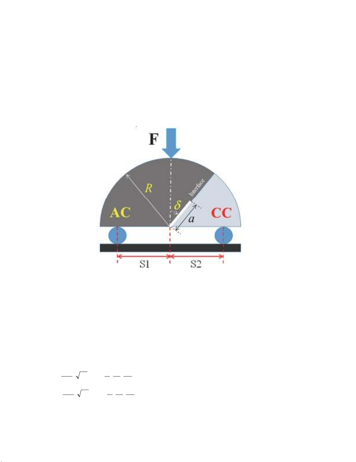
The SCB specimen typically contains an angled crack and is subjected to three-point bending. Fig. 2
shows the geometry and loading conditions for the bi-material SCB test specimen (BSCB), introduced
296
in this paper, for examination of the mixed mode propagation of a crack along the interface of two
dissimilar materials. In this test specimen, a semi-circular specimen of radius R that contains an edge
interface crack of length a with inclination angle of , is loaded asymmetrically by a three-point bend
fixture. As illustrated in Fig. 2, the crack exists at the interface of AC and PCC. While the specimen is
easily manufactured, it does not need complicated loading fixtures for using in conventional testing
machines. The state of mode mixity in the BSCB specimen can be easily altered by changing the
locations of two bottom supports (S1 and S2) and the crack inclination angle ().The mode I and mode
II contributions can be controlled simply by choosing appropriate values for S1, S2, and . Hence
different mode mixities can be obtained in the BSCB specimen. The specimen has been frequently used
in the past but only for the simple case of homogeneous material (single material) in order to obtain
fracture toughness for several engineering materials including, rocks, concrete, asphalt, polymers, etc.
(Ayatollahi et al., 2006; Lim et al., 1994; Li & Marasteanu, 2005, Aliha & Fattahi Amirdehi 2017,
Aliha et al. 2012,2015b, Aliha & Ayatollahi 2013).
Fig. 2. Scheme of the BSCB specimen made of asphalt concrete and Portland cement concrete
In order to evaluate tensile/ shear bond strength between the PCC and AC using interfacial fracture
mechanics concepts, it is necessary to define the state of mode mixity by calculating the mode I and
mode II stress intensity factors (K
I
and K
II
) for different loading positions and crack lengths. The finite
element method was employed in this research to determine K
I
and K
II
in the BSCB specimen.
4. Calculation of the stress intensity factors
The stress intensity factors K
I
and K
II
for the BSCB specimen are functions of the crack length (a),
crack inclination angle (), the locations of loading supports defined by S1 and S2, and elastic properties
of both bonded materials. For a given material property, the stress intensity factors can be expressed as
the following normalized form:
(1)
(2)
)
2
,
1
,,()(
2
)
2
,
1
,,()(
2
R
S
R
S
R
a
Ya
Rt
F
K
R
S
R
S
R
a
Ya
Rt
F
K
IIII
II
where t is the specimen thickness and Y
I
and Y
II
are the geometry factors corresponding to mode I and
mode II, respectively. For calculating Y
I
and Y
II
, different finite element models of the BSCB specimen
were analyzed using the finite element code ABAQUS. Details on equations 1 and 2 can be found in
M. M. Mirsayar et al.
/ Engineering Solid Mechanics 5 (2017)
297
Mirsayar (2014). In the models, the following geometry and loading conditions were considered: R =
76.2mm, t=25 mm, a=38.1mm, F = 1000N and different values for crack inclination angles (), S1, and
S2. It should be mentioned that according to equations 1 and 2, the calculated value for the stress
intensity factors can be obtained once the finite element simulation is performed in any external load,
F, by a simple multiplication of F
cr
/ 1000 to the numerical results, where F
cr
is the ultimate fracture
load. Since the original goal of the current research is to evaluate bond strength AC and PCC layers, in
this research, we have used these two materials for finite element simulations. Same procedure can be
done for any combination of the materials. The elastic properties used for the finite element modeling
of the asphalt concrete and Portland cement concrete are: E
asph
=4.9 GPa, =0.35, E
conc
=40.7GPa, =0.2.
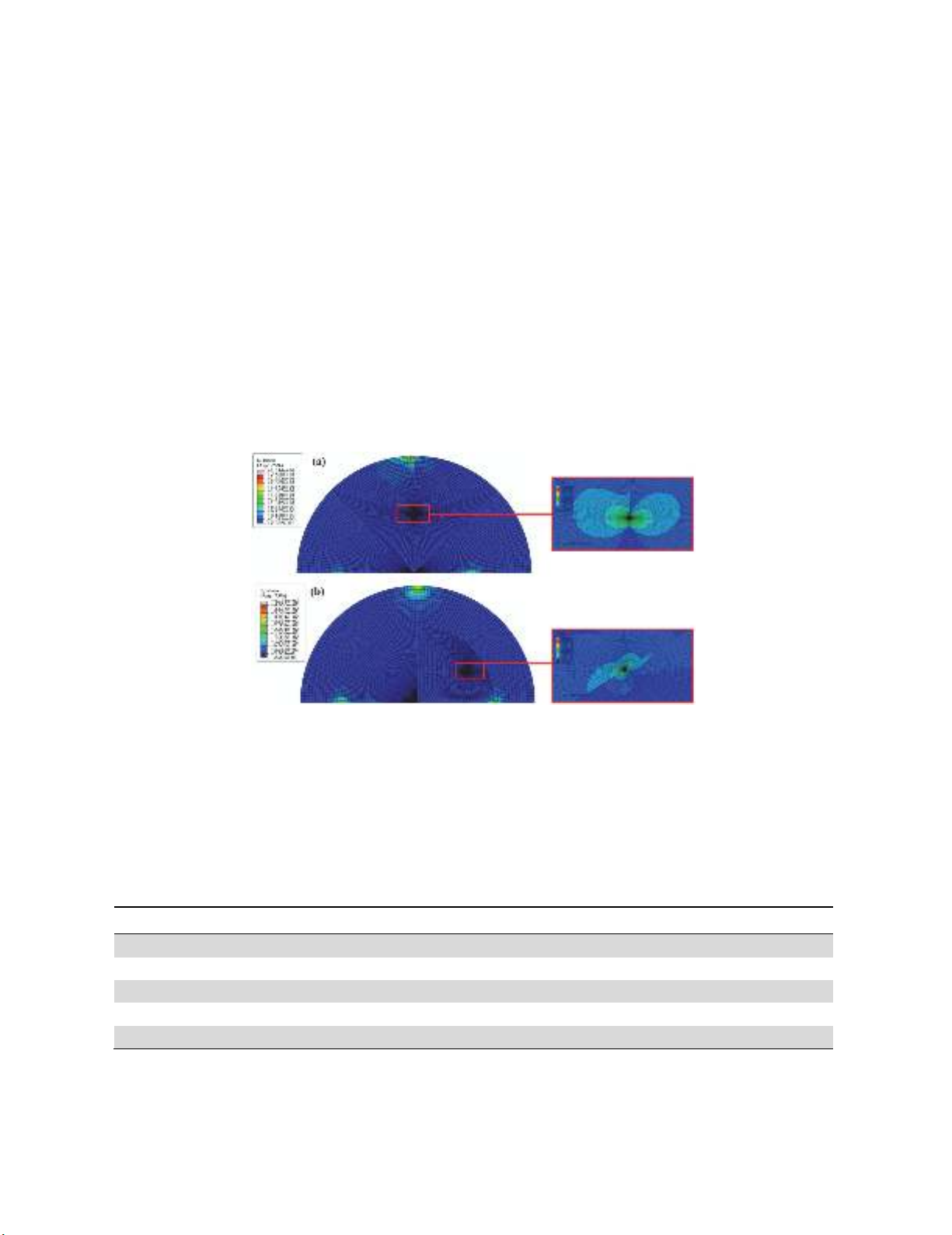
Fig. 3 shows mesh patterns generated for simulating the BSCB specimen as well as the von Mises stress
contour plot for two different mode mixities: pure mode I (K
II
= 0) and pure mode II (K
I
= 0). In pure
mode I, the stress contour is symmetric relative to the crack plane. However, because of the material
mismatch, the stress contour is discontinuous at the interface. For pure mode II, the contour plot is
asymmetric with respect to the crack plane showing the significant effect of shear stress. The singular
elements were considered in the first ring of elements surrounding the crack tip for producing the square
root singularity of stress/strain field. A J-integral based method built in ABAQUS was used for
obtaining the stress intensity factors directly from software.
Fig. 3. Mesh pattern of the BSCB specimens as well as plots of von Mises stress contours
in front of the interface crack tip at a) pure mode I, b) pure mode II conditions
Table 1 lists the values of Y
I
and Y
II
associated with pure mode I, pure mode II and three mixed
mode conditions. It is seen that the proposed specimen is able to cover different mixed mode conditions
from pure mode I (M
e
=1) to pure mode II (M
e
=0).
Table 1. Finite element simulation results of BSCB at different mixed mode conditions
a (mm) (deg) S1 (mm) S2 (mm) Y
I
Y
II
M
e
38.1 0 50 38 0.323 0.000 1.00 (pure mode I)
38.1 0 30 20 0.154 0.062 0.758
38.1 0 60 15 0.149 0.120 0.569
38.1 45 50 50 0.105 0.154 0.382
38.1 58 50 50 0 0.1 0 (pure mode II)
![Bài tập tối ưu trong gia công cắt gọt [kèm lời giải chi tiết]](https://cdn.tailieu.vn/images/document/thumbnail/2025/20251129/dinhd8055/135x160/26351764558606.jpg)