REGULAR ARTICLE
Application of the lines of defence method to the molten salt
fast reactor in the framework of the SAMOFAR project
Stéphane Beils
1
, Delphine Gérardin
2
, Anna Chiara Uggenti
3,*
, Andrea Carpignano
3
, Sandra Dulla
3
, Elsa Merle
2
,
Daniel Heuer
2
, and Michel Allibert
2
1
Framatome, 10 rue Juliette Récamier, 69006 Lyon, France
2
LPSC-IN2P3-CNRS, UJF, Grenoble INP, 53 rue des Martyrs, 38026 Grenoble, France
3
NEMO Group, DENERG, Politecnico di Torino, C.so Duca degli Abruzzi 24, 10129 Torino, Italy
Received: 3 May 2019 / Received in nal form: 19 July 2019 / Accepted: 10 September 2019
Abstract. The Molten Salt Fast Reactor (MSFR) with its liquid circulating fuel and its fast neutron spectrum
calls for a new safety approach and adaptation of the analysis tools. In the frame of the Horizon2020 program
SAMOFAR (Safety Assessment of the Molten Salt Fast Reactor), a safety approach suitable for Molten Salt
Reactors has been developed and is now applied to the MSFR. For this purpose, the Lines of Defence (LoD)
method is selected to drive the design consistently with the Defence in Depth principle. This paper presents the
main characteristics of the method, along with some practical guidelines to apply it to the specic case of the
MSFR; moreover, some initiating events are analyzed through the implementation of the LoD tool. The
outcomes of this analysis drive the design evolution.
1 Introduction
Nuclear power is recognized as an outstanding source for
base load low-carbon electricity production and it is
included in all energy scenarios in the European Energy
Roadmap 2050. The development of fast breeder reactors
and associated fuel cycles is fundamental to improve the
utilization of nuclear fuel.
New generation nuclear reactors are expected to be
designed with the highest safety standards. In that frame,
there is an incentive to look for nuclear concepts with
enhanced intrinsic safety features. Optimized waste
management is also an important goal for the new
generation of nuclear systems.
Together with ve other nuclear energy systems, the
Molten Salt Fast Reactor (MSFR) was selected by the
Generation IV International Forum (GIF) due to its
promising design and unique safety features [1,2] and is
currently studied in the frame of the Horizon2020 program
SAMOFAR (Safety Assessment of the Molten Salt Fast
Reactor). Its main objective is to prove the reliability of
the innovative safety concepts of the MSFR by advanced
experimental and numerical techniques, to deliver a
breakthrough in nuclear safety and optimal waste
management[3].
Using the Functional Failure Mode and Effects
Analysis (FFMEA) and the Master Logic Diagram
(MLD), a list of accidents initiators has been identied
for the plant state corresponding to the nominal conditions
during power production [4,5,6,7]. In parallel, a list of
design key-points that are relevant for safety and that
should be further documented has been provided [6].
Successively, the method of the Lines of Defence (LoD) has
been applied for some of the selected initiating events. This
method helps the designer to determine whether sufcient
safety provisions are put in place for a given risk with the
aim of ensuring that every accidental evolution of the
reactor state is always prevented by a minimum set of
homogenous (in number and quality) safety provisions
the Lines of Defence before a given situation may arise.
The objective of this paper is to describe the implementa-
tion of the Lines of Defence method and to present its rst
results and the way it drives the on-going design work,
consistently with the Defence in Depth principle.
In Section 2, a brief description of the MSFR current
design considered in the SAMOFAR project is presented
[8]. Afterwards, in Section 3 the methodology used to
perform the work is summarised. Section 4 presents the
rst results. In the end, some conclusions and further
perspectives are reported.
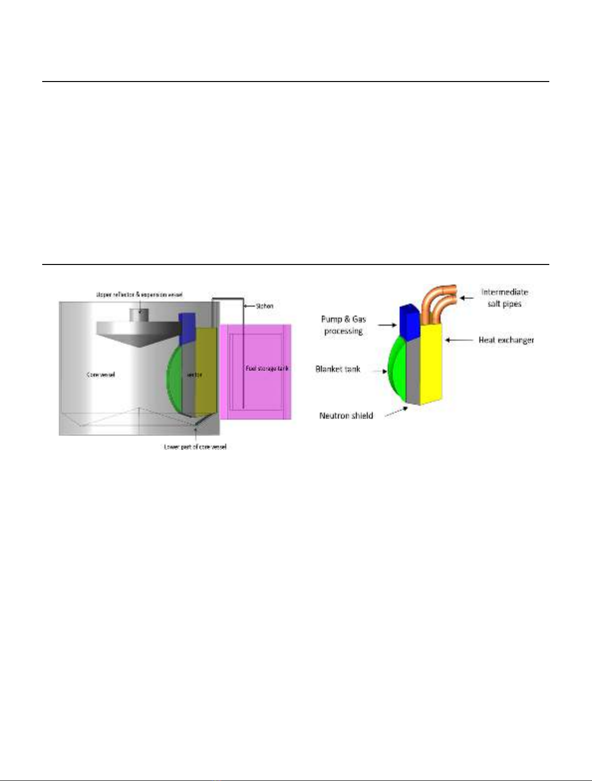
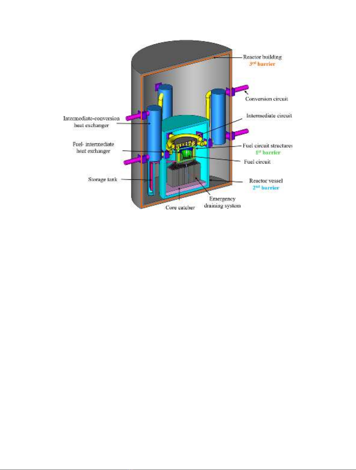
2 Description of the system
2.1 General description
The reference MSFR is a 3 GW thermal power reactor with
a fast neutron spectrum and operated in the thorium fuel
*e-mail: anna.uggenti@polito.it
EPJ Nuclear Sci. Technol. 5, 18 (2019)
©S. Beils et al., published by EDP Sciences, 2019
https://doi.org/10.1051/epjn/2019031
Nuclear
Sciences
& Technologies
Available online at:
https://www.epj-n.org
This is an Open Access article distributed under the terms of the Creative Commons Attribution License (http://creativecommons.org/licenses/by/4.0),
which permits unrestricted use, distribution, and reproduction in any medium, provided the original work is properly cited.
cycle. The plant includes three main circuits involved in
power generation: the fuel circuit, the intermediate circuit
and the energy conversion circuit, which is connected to the
electrical grid and the heat sink. The main characteristic of
the MSFR is the use of a liquid fuel, in the form of a molten
salt, which circulates in the fuel circuit. Therefore, this
molten salt plays both the roles of fuel and heat transport.
The fuel circuit is not pressurized. The selected fuel salt is a
binary uoride salt with, in its initial composition, 77.5 mol%
of lithium uoride; the remaining 22.5 mol% are a mix of
heavy nuclei uorides including ssile and fertile matters.
The properties of the fuel salt and the characteristics of the
fuel circuit, considered for the following analysis, are listed in
Table 1. As presented in Figure 1, the fuel circuit geometry
[8,12] includes the core vessel used as a container for the fuel
salt, in which 16 cooling sectors are disposed circum-
ferentially. The 18 m
3
of fuel salt are equally distributed
between the core (central area where most of the ssions
occur) and the cooling sectors. Each sector comprises a heat
exchanger, a pump, a gas processing system, and a fertile
blanket tank. Neutron shielding is positioned between the
breeding blanket and the heat exchangers to protect the heat
exchangers from neutron radiation. In addition, reectors
are located at the bottom and the top of the vessel to protect
the structures located outside the core. The fuel circuit
structures are made of Hastelloy N, which is a nickel based
alloy specically developed for uoride molten salt reactor
[13]takingbenet of the experiencefeedback from Oak Ridge
National Laboratory (ORNL) in the 50sand60s with the
Aircraft Reactor Experiment (ARE) and Molten Salt
Reactor Experiment (MSRE).
The fuel circuit is connected to the intermediate circuit
through the heat exchangers. Four intermediate circuits are
foreseen, each of them feeding four cooling sectors. The
structural material of the intermediate circuit is not selected yet.
The fuel salt undergoes two types of treatment: an
online gas bubbling in the core and a remote mini-batch
processing on-site. The bubbling system is used to clean
the salt from gaseous ssion products and metallic
particles. The gas is injected at the bottom of the core
and recovered at the top to be cleaned up in the gas
processing unit before being re-injected in the core. The
chemical fuel processing is performed in the processing
unit, in a separated building on the same site. Fuel
samples are daily extracted/injected in the fuel circuit,
during the reactor operation, thanks to the sampling
Table 1. Properties of the fuel circuit and intermediate circuit materials [8,9,10,11].
Fuel circuit Fuel salt initial composition
Mean fuel salt temperature in fuel circuit (°C)
LiF-ThF
4
-
233
UF
4
(77.5-20-2.5 mol%)
725
Fuel salt temperature rise in the core (°C) 100
Total fuel salt volume (m
3
)18
Total fuel salt cycle in the fuel circuit (s) 3.9
Fuel salt dilation coefcient (g.cm
3
.°C
1
) 8.82. 10
4
Fuel salt density (g.cm
3
) 4.1
Fuel salt melting temperature (°C) 585
Fuel salt boiling temperature (°C) 1742
Fuel circuit structural material Hastelloy N
Intermediate circuit
Intermediate salt Fluoroborate (NaF-NaBF
4
)
Total intermediate salt volume (m
3
)100
Melting temperature (°C) 384
Fig. 1. Schematic representation of the core vessel with one cooling sector (left) and description of a sector (right).
2 S. Beils et al.: EPJ Nuclear Sci. Technol. 5, 18 (2019)
system. In fact, fuel salt samplings are regularly performed
to control and adjust the fuel chemical composition and its
ssile/fertile inventory.
Figure 2 gives an overview of the different systems and
their localization in the reactor building. The fuel circuit is
connected to other auxiliary and safety systems. In
particular, there are two types of draining systems: the
routine draining system to the storage areas and the
Emergency Draining System (EDS) [8,12]. The routine
draining system, triggered only by active means, is used to
transfer the fuel from the core vessel to storage areas. On
the other hand, the EDS is located under the core vessel to
allow a gravitational draining. The fuel circuit is connected
to this system through valves located in the lower part of
the core vessel. Several types of valves are foreseen,
including active valves, such as valves automatically
triggered (for example by the detection of a too high
temperature/pressure), or by operator action and passive
valves, such as fusible valves triggered by the fusion or the
rupture of a component under too high temperature
conditions. In addition, a core catcher is located in the
lower part of the reactor vessel. The core catcher is notably
able to recover leaking fuel salt in case of EDS failure. It is
based on the spreading of the fuel on a large area and on the
mixing of the salt with a compatible sacricial salt, which
would guarantee its subcriticality and ease its cooling (the
related decay heat removal circuit is not designed at this
stage). It is assumed that the fuel could be recovered from
the EDS to restart the reactor, while the fuel salt at the core
catcher level would be lost.
In Figure 2, the heat exchangers between the
intermediate circuit and the energy conversion circuit
are located within the reactor building. It has to be noted
that other design options are currently studied, where these
heat exchangers are located outside of the reactor building.
2.2 MSFR specicities impacting the safety functions
The MSFR has different features from most current
reactors. The objective of this paragraph is to explain some
of the characterizing aspects of MSFR that are related to
the three safety functions: reactivity control, heat removal
and connement.
2.2.1 Reactivity control
Some specicities of the MSFR affect the neutronics. First,
the delayed neutron precursors are drifted in low
importance areas because of the fuel motion. This implies
a reduction of the effective fraction of delayed neutrons
from about 310 to 124 pcm [14]. Then, the MSFR has a
strong negative global thermal feedback coefcient, around
8 pcm/K [15], coming half from the Doppler feedback
effect and half from the density feedback effect. The density
effect comes from the fuel expansion and is linked to the
presence of free levels in the upper part of the fuel circuit: in
case of fuel expansion, a small portion of the fuel salt is thus
pushed from the core central area where most of the ssions
occur toward the upper part of the fuel circuit where
ssions are negligible. Free levels are located at the level of
the pumps, at the level of the separation chamber of the gas
processing unit and at the level of the expansion vessel (a
tank located just above the core in the upper reector). The
intrinsic temperature feedback effects act rapidly since the
Fig. 2. Schematic view of the main systems located in the reactor building; proposals for the connement barriers are highlighted.
S. Beils et al.: EPJ Nuclear Sci. Technol. 5, 18 (2019) 3
heat is produced directly in the coolant. This inherently
limits power excursion in case of accidental transients.
Thanks to the fuel online cleaning and the processing/
loading during reactor operation, the fuel composition is
assumed not to encounter large variations. In fact, the
amount of ssile material dissolved in the critical zone of
the fuel circuit is just necessary to maintain a critical state
and fertile material periodically injected in the core without
needing to shut down the reactor. Therefore, it should not
be necessary to have a large in-core reactivity margin to
compensate the fuel depletion.
Thanks to the negative thermal feedback effects, the
reactor can be mainly driven by heat extraction [14]. No
control rods are currently foreseen in the MSFR design.
Nonetheless, the injection of gas bubbles in the core may be
used to control the reactivity. Besides, fuel salt draining
towards the routine draining tank or toward the EDS can
ensure reactivity control.
2.2.2 Heat removal
In normal operation, the systems involved in the heat
evacuation are the fuel circuit, the intermediate circuit, the
conversion circuit and the heat sink. Additionally, several
systems, preferentially relying on passive mechanisms, are
foreseen to evacuate the residual power from the fuel with,
in particular, the implementation of an emergency cooling
system for the intermediate circuit, with air as heat sink.
Besides, one of the consequences of the fuel liquid state is
the possibility of a passive reconguration of the geometry
of the core. In case of failure to remove heat from the fuel
circuit, the fuel can be drained gravitationally toward the
EDS where its subcriticality is ensured. The cooling system
of the EDS, also under study in the frame of the
SAMOFAR project, aims at allowing a passive removal
of the residual heat with no need for forced convection
(both in the EDS and in its cooling circuit) [8,12,16].
One of the MSFR specicities is the delocalization of a
part of the residual power out of the core, notably because
of the in-core gas bubbling and of the fuel processing. On
the one hand, the residual power produced in the salt is
reduced and, 1s after reactor shutdown, represents only
4% of the nominal power. On the other hand, the heat
evacuation from the bubbling system (representing 1.5%
of nominal power 1s after reactor shutdown) and from the
processing unit (representing 0.06% of nominal power 1s
after reactor shut down) should also be handled with [17].
Fission products extracted in reprocessing and stored in
special on-site tanks are not further considered in this
article.
2.2.3 Connement of radioactive materials
Preliminary safety studies [17] have led to the denition of
the integrated fuel circuit geometry presented above (see
Fig. 1) and now used as reference in the SAMOFAR
project. In case of heat exchanger leak, fuel dispersion is
limited by using a slightly higher operating pressure in the
intermediate circuit than in the fuel circuit. In addition,
several valves are implemented to be able to ensure
the connement of the radioactive materials at the
intermediate circuit level if needed: on the intermediate
circuit leg entering the core vessel (this valve could also be
used to isolate a sector for maintenance operations), on
the intermediate circuit leg crossing the reactor vessel and
on the intermediate/conversion circuit leg (depending on
the secondary heat exchanger location) crossing the
reactor building.
In the frame of the SAMOFAR project, several
proposals have been investigated for the denition of the
MSFR connement barriers. In one of these proposals, the
connement barriers with regard to fuel salt in the fuel
circuit, in normal operation during power production, are
dened as follows [6]:
1st barrier: fuel circuit containment structures (repre-
sented in green on Fig. 2) that ensure fuel containment
during normal operation;
2nd barrier: reactor vessel (represented in blue on
Fig. 2) that ensures fuel containment when the function
can no longer be ensured by the rst barrier (e.g., rst
barrier leakage or fuel salt draining in the EDS);
3rd barrier: reactor building (represented in orange on
Fig. 2) that ensures protection of the two rst barriers
with regard to external hazards, and may have a dynamic
connement function (and static connement function in
case of postulated failures of the two rst barriers).
The constraints on these connement barriers are quite
different from the ones classically encountered on solid
fuelreactors. It is worth noting here that the MSFR fuel
circuit is at low pressure. Since both fuel and intermediate
circuits are at low pressure (the only circuit with a high
pressure being the energy conversion circuit) and no highly
exothermic chemical reaction has been identied until now,
the constraints on the third barrier, the reactor building,
may be rather low (potentially no need for a high pressure
resistant containment, provided the energy conversion
circuits are located out of the reactor building).
The fuel can be located in several areas of the plant:
storage tanks, sampling system, processing unit, etc. Thus,
the denition of the connement barriers should be
undertaken for each possible location of the fuel and for each
state of the reactor operation: power production, mainte-
nance, start up, shut down, normal and accident conditions.
3 Lines of Defence methodology
The main objective of the Lines of Defence (LoD) method is
to ensure that every accidental evolution of the reactor
state is always prevented by a minimum set of homogenous
(in number and quality) safety provisions called Lines of
Defence before a given situation may arise. It allows the
designer to determine whether sufcient safety provisions
are put in place between initiating events and a given
accidental situation, and contributes to justify the
acceptable safety level of the plant in the licensing process.
It is a deterministic method particularly well suited to early
design phases as it can be used as a pragmatic guidance for
the architecture of the safety components and systems,
consistently with the Defence in Depth principle. The
method is also relevant for the identication and the
classication of accidental sequences.
4 S. Beils et al.: EPJ Nuclear Sci. Technol. 5, 18 (2019)
This method has been widely used in the past on French
fast reactors, and is being used in the fast reactor project
ASTRID [18] and other projects (e.g. Jules Horowitz
Reactor in Cadarache), for the prevention of the reactivity
control and decay heat removal safety function(s).
3.1 The LoD method generic steps
A very rst step of the method is to identify and
characterize the situations for which prevention is studied.
Then, the events that may lead to the situation considered
(so-called initiating events) must be identied.
For a given accidental situation to be prevented
(typically, severe accident), the main steps of the LoD
method are:
1. dene the required number and quality of LoDs to be
provided for the prevention of this accidental situation
(the analysis is performed for each function necessary to
prevent the accident situation);
2. for each initiating event, ensure that an adequate set of
LoDs (in terms of number and quality) is provided:
at early design stages when the safety architecture is to
be built, the method provides a guidance to sketch the
safety architecture;
when the safety architecture is dened into more
details, the method permits to check its sufciency,
and allows the classication of accidental sequences
upstream accident analyses.
3.2 Lines of Defence denition
There are three types of LoDs: the preventive measures of
the initiating event (the low occurrence frequency of the
initiating event can by itself stand for a line of defence); the
measures aimed at limiting the consequences of the
initiating event by means of specic equipment or human
actions; and the intrinsic behaviour and natural resistance
to the progression of the initiating event.
The lines of defence are classied according to their
expected availability/reliability:
Strong LoD, type a(initiating event with a frequency
lower than 10
3
to 10
4
/year, equipment with a failure
rate of approximately 10
3
to 10
4
when needed);
Medium LoD, type b(initiating event with a frequency
lower than 10
1
to 10
2
/year, equipment or operators
procedure with a failure rate of approximately 10
1
to
10
2
when needed).
The experience feedback [18] is that the following
provisions can be considered as LoD:
Strong LoD (type a) can include active systems
designed in accordance with the standards of the nuclear
industry and comprising internal redundancies as well as
electrical back-up; passive equipment, exploited like
connement barriers, designed in accordance with the
standards of the nuclear industry; intrinsic behaviour
providing a long grace period to perform human
corrective actions. The systems used as strong LoD
must be designed to withstand hazards (notably
earthquake).
Medium LoD (type b) can include active systems
without internal redundancy; actions by the operator in
the frame of procedures.
Two medium independant lines of defence may be
considered as equivalent to one strong line of defence.
One of the essential points in the application of this
method is to make sure that the LoDs implemented for a
specic initiating event are independent from the initiating
event and from each other in order to minimize the risks of
common mode failure, by ensuring sufcient diversication
and functional and physical independence between
them [18].
3.3 LoD general application in the MSFR context
3.3.1 Severe accident denition in the MSFR context
The denition of the severe accident is key in the usual
application of the LoD method.
For example, on the ASTRID project, a complete core
meltdown is considered as severe accident. Then, for each
initiating event, the equivalent of three LoDs is imple-
mented (at least two strong lines and one medium line,
2·a+b) upstream from this assumed situation of severe
accident [18].
Cliff edge effects studies, allowing to precisely dene
severe accident for the MSFR, are still on-going. For the
MSFR, considering the barriers envisaged (see Sect. 2.2.3),
a situation with potential for large early radiological
releases in the environment would require at least the
failure of the two rst barriers.
The general objective retained is thus to prevent the
situation of failure of the two rst barriers, with a potential
for large early radiological releases in the environment,
through at least two strong and one medium lines of
defence (2 ·a + b). The related mitigation means of such
situation are not further developed in the present article.
As regard to situations that may need to be practically
eliminated (i.e., severe accident situations that may lead to
large early releases and that would not be reasonably
manageable), none has been identitied until now.
3.3.2 Required LoDs after MSFR initiating events
Consistenly, the purpose of investigating the challenges of
the rst barrier has driven the process of identication of
the initiating events. (In case of failure of the rst barrier,
safety provisions to ensure leaktightness of the second
barrier are then to be studied).
The initiating events challenge the reactor and its
safety functions; they are grouped in families depending on
their potential effects on the reactor [5]. For each family,
specic initiating events to be further analysed have been
selected. In this paper, the application of the LoD method
to some of them is presented. An initiating event initiates
the accidental sequence. The accidental sequence is the
evolution of the accident from the initiating event until the
nal consequences and damage. The consequence is the
effect in physical terms of a particular accident and the
damage represents the last impact of failures/accidents on
the population, the environment, structures/assets, and
reputation (in this work it is quantied in terms of loss of
S. Beils et al.: EPJ Nuclear Sci. Technol. 5, 18 (2019) 5