
* Corresponding author.
E-mail addresses: atma.yudha.prawira@gmail.com (A. Y. Prawira)
© 2019 Growing Science Ltd. All rights reserved.
doi: 10.5267/j.esm.2019.6.001
Engineering Solid Mechanics 7 (2019) 163-178
Contents lists available at GrowingScience
Engineering Solid Mechanics
homepage: www.GrowingScience.com/esm
Logging while drilling operation
Atma Yudha Prawiraa,b*
aMechanical Engineering Department, Balikpapan University, Indonesia
bIndustrial Engineering Department, Mercu Buana University, Jakarta, Indonesia
A R T I C L EI N F O A B S T R A C T
Article history:
Received 25 December, 2018
Accepted 4 June 2019
Available online
4 June 2019
This research presents detailed notes on the penetrating geological formations of the wellbore.
Logs can be presented in two forms of good geological logs, means visual inspection of surface-
carrying samples, and geophysical logs, means physical measurements by instruments that are
lowered into holes. Logs that are created during drilling are called real-time logs. LWD tool is
produced from real-time data transmitted to the surface computer from downhole. Three common
services are Natural Gamma Ray, Resistivity, and Porosity and Bulk Density. The output of an
LWD service is a log. A log is a graphical representation of the properties of the formation. Some
factors that affect data quality are Depth Calculation, Sensor Malfunction and LWD Tools
Measurements Fault. During drilling, borehole path monitoring is the important thing to be
maintained because the quality of LWD data is critical for the success of any LWD job. Therefore,
the field engineer has to understand the factors that affect data quality. Quality Control Process is
the key to ensure that the tools are working properly.
© 2019 Growing Science Ltd. All rights reserved.
Keywords:
Drilling Operation
Real Time Drilling
Drilling Parameter
Borehole Path Monitoring
Borehole Directional Survey
1. Introduction
Logging while drilling means taking measurements of the petrophysical properties of the formation
(e.g., hydrocarbon saturation, lithology) around the borehole as the well is drilled. The client uses LWD
measurements to evaluate the production value of the reservoir during drilling and after drilling is
complete. Therefore, it is important that LWD data be accurate. Three common services are Natural
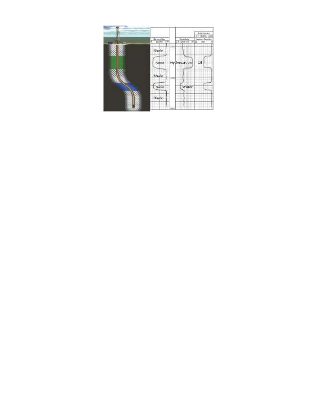
Gamma Ray, Resistivity, and Porosity and Bulk Density. The output of an LWD service is a log (see
Fig.1). A log is a graphical representation of the properties of the formation. Logs are critical documents.
Analysis of all the log services together is called log interpretation. From this interpretation, the client
can derive accurate values for such properties as hydrocarbon saturation (Pike, 2002). The logs for each
service are shown to the right.
164
Fig. 1. LWD Log Services
Fig. 1 describes the log from each LWD services which describe the formation evaluation. From the
graphic, We can know Natural Gamma Ray measures the naturally occurring gamma rays in the
formation. It indicates the composition or type of rock. The log is used to locate sands, which generally
are areas of production, or reservoirs. Resistivity measures the degree to which the formation opposes
the flow of an electric current. The log indicates whether the fluid in the sand is hydrocarbon or water.
This service is also an indicator of formation pressure in shales. Porosity and Bulk Density commonly
uses a radioactive source to measure the percentage of the formation occupied by pore spaces (Melissinos
& Napolitano, 2003). The log indicates if the hydrocarbon in an area is oil or gas. Almost all oil and gas
produced today comes from pore spaces. The production value of a reservoir is dependent on the
percentage of hydrocarbon saturation in those pore spaces, i.e., the percentage of the pore space that is
occupied by hydrocarbon rather than water (Collett et al., 2012).
During drilling, the client uses LWD data to make quick and accurate decisions about Directional
Drilling and Hazards Prevention. Using log information and directional drilling technology, it is possible
to steer the well path to Stay within shallow (thin) payzones, Drill multiple entry points to cut through a
reservoir at a better angle and increase the drainage area, and Steer the well path to include more than
one target reservoir. Besides that, by using log information, the rig can monitor and maintain borehole
pressure. Borehole pressure must be kept at a level that is higher than formation pressure (Bittar et al.,
2017). The pressure difference prevents hazardous situations such as a kick, where higher pressure
formation fluid enters the borehole.
When drilling is complete, the client uses LWD data to evaluate the formation and make accurate
financial decisions, such as whether to produce the well. It means that by using log information, the client
may decide to extract the fluids depending on the analysed profitability of the reservoir. Another decision
is abandon the well. The client may decide the well will not be profitable and will abandon the well. The
last one is drill more wells in the same area. The well can be side-tracked to reach additional payzones
(Qleibo et al., 2014).
2. History of Logging While Drilling
Well logging was first used by Conrad and Marcel Schlumberger who was the founder of the
Schlumberger company in 1926. At that time, they adopted a Geoelectric Sonde commonly used in
searching for mineral subsidized seed prospects for subsurface applications in the oil and gas world. They
use the recording to determine the resistance of the formation that lies beneath the surface. So the log
that was first used in industrial history is log resistivity. The Sonde is discharged in the borehole at certain
periodic intervals and its resistivity is directly recorded on the graph paper. In 1929 electrical resistivity
logs were introduced on a commercial scale in Venezuela, the United States and Russia. In subsequent
developments well logging is used for the correlation and identification of hydrocarbons. The film data
recorder was later developed in 1936. For depth determination in well logging geophysics developed in
A. Y. Prawira / Engineering Solid Mechanics 7 (2019)
165
1930. Then gamma ray logs and neutron logs began to be used in 1941 (Schlumberger, 1985). Since the
first log runs, geophysical well logging has grown to a billion dollars in a global industry serving a variety
of industry and research activities. Well logging geophysics is a key technology in the petroleum industry.
In the minerals industry, it is a widely used method for both exploration activities and for monitoring
work in enforcement. In the geophysical well logging, many different physical properties can be
identified for the geological characteristics surrounding the well. The ability to identify different traits is
the best ability in well logging geophysics. Different types of information obtained reflect different
aspects of geology and often complement each other in nature (Schlumberger, 1989).
Based on the above explanation, it is very clear that Well logging is a very appropriate method for
determining the source of oil in the soil, as well logging provides the necessary data to evaluate the
quantity of petroleum quantities in actual situations and conditions. Furthermore, it will provide
assurance on the results of resource and reserve estimates. (Hearst & Nelson, 1985). Therefore, the use
of well logging in petroleum exploration is important and necessary, especially in the determination of
sources and estimates of resources or reserves (Chemali & Dirksen, 2017).
Since 1926 until now, well logging technology has undergone many recent developments and
innovations to accommodate the needs of oil and gas industry in finding and knowing the prospect of
petroleum in a reservoir. from start to conventional tools like GR log, SP log, Density log etc. up to
unconventional tools like NMR, dipmeter. even the data retrieval technique has now developed into LWD
(Logging While Drilling) where between log and drilling recording is done simultaneously, so hopefully
this condition can reflect the most "real time" condition of the formation (Schlumberger, 1985).
2.1. Logging While Drilling Method
To take measurements of the formation while drilling, Many company have developed LWD tools.
These tools are designed to provide one or more logging services. Each tool is installed inside a drill
collar at the shop before being sent to the rig. The rig crew adds the LWD drill collar to the drillstring,
close to the drill bit, before drilling begins. Sensors inside the LWD tool take the formation
measurements. The sensors can be powered either by the MWD tool or by lithium batteries in the LWD
tool (Ellis & Singer, 2007).
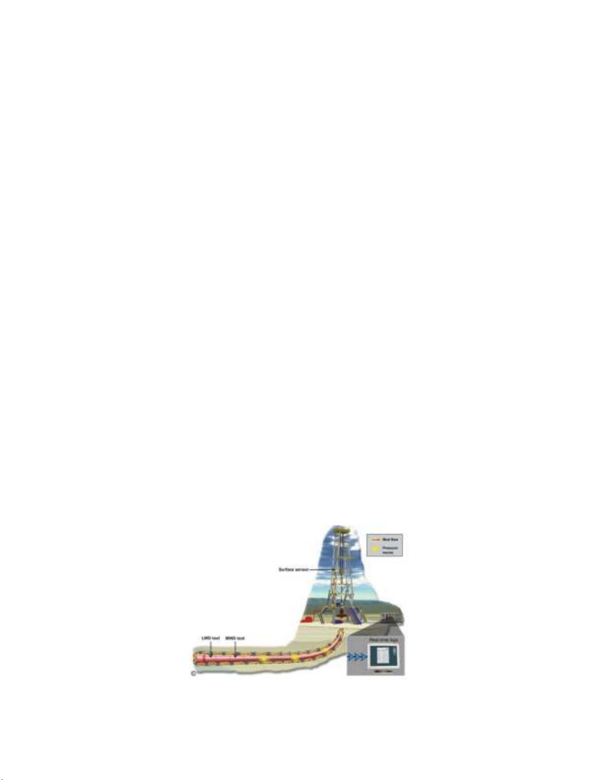
Logs that are created during drilling are called real-time logs (see Fig 2). In Figure 2 explain how
LWD tool produced from real-time data transmitted to the surface computer from downhole. To transmit
data, the LWD tool sends its measurements to the MWD tool. The MWD tool sends the data uphole by
producing pressure waves in the mud inside the drillstring. The signal wave is detected by a surface
sensor and sent to the surface computer for processing into logs. Due to constraints imposed by drilling
and the method of telemetry, real-time data is typically low-density, and it includes only one or two
variables per datapoint. Real-time logs provide enough information for the client to make quick decisions
during drilling (Youmans, 1986; Herrmann, 1997).
Fig. 2. Logging While Drilling Produce Real Time Log

166
In addition to producing real-time data, the LWD tool also records data in its internal computer
memory. There is no limit to the amount of data that can be recorded other than the size of the tool's
memory. Therefore, recorded data typically has a higher density and includes more variables per
datapoint than real-time data. This gives a higher resolution image of the formation (Darling, 2005).
Recorded mode data is retrieved from the LWD tool when drilling stops and the tool is brought to the
surface. The field engineer dumps the data from the tool into the surface computer to produce recorded
mode logs. Recorded mode logs are given to the client at the end of each bit run and at the end of the
job.
2.2. Logging While Drilling Operation
The field engineer runs the LWD bit run after the tools are made up in the BHA, and the BHA goes
in the borehole. To run the job, the field engineer performs specific tasks during each bit run and at the
end of the job. In this section, you will learn what the field engineer does before, during, and after the
completion of an LWD bit run and after the completion of an LWD job. Tasks: (1) Tripping In, (2)
Drilling, (3) Tripping Out, (4) Tools at Surface, (5) Post-Job Tasks (Li, 2003).
2.2.1. Tripping In
At the beginning of each job, the field engineer starts a new tally book that is used for the duration of
the job. Before the start of each bit run, the field engineer makes a list in the tally book of the stands or
joints to be used in the run. Next, the field engineer calculates Pipe + BHA length and Driller's Depth for
each stand or joint and enters the values into the tally book (Baaziz & Quoniam, 2015).
At the start of each bit run, when the BHA is in the shallow part of the borehole, the field engineer
tests the downhole tools. The LWD tools are tested to make sure they are communicating with each other
and with the MWD tool and surface computer. To perform the test, the field engineer asks the driller to
start the pumps. When the flow rate rises above a set threshold, the MWD tool turns on and begins data
transmission. All the LWD tools should be taking readings and sending data to the MWD tool. To verify
this, the field engineer looks at the tool readings and the status word from each tool in the surface
computer. If the surface computer does not receive any data it could indicate a problem with the SPT
(surface sensor for MWD signal), computer demodulation setup, or downhole tools. If the problem
cannot be corrected with the tools still in the borehole, the tools will need to be pulled out of hole and
either fixed or replaced (Pardo et al., 2013).
If any of the LWD tool readings show maximum values, there is a communication problem in the
extenders between the LWD tools and the MWD tool. The maximum value is dependent on the number
of bits in the binary word. When the MWD tool turns on, it takes a survey and transmits the data uphole.
To determine if the tool is operating correctly, the field engineer checks G, H and Dip in the Survey
Control Panel. G, H and Dip are the primary reference criteria for evaluating a downhole survey
(Herrman, 1997). The field engineer knows the tool is working properly when G, H and Dip are within
the tolerances defined by the reference and deviation values coming from Geomag.
When the bit is 2 to 4 stands, or joints, off bottom, the field engineer sets Block Position, Bit Depth,
and Hole Depth in the surface computer. To do this, the field engineer has the driller place the top of the
tool joint at the rotary table. After setting Bit Depth, the engineer compares it to Driller's Depth as the
last 2 to 4 stands are tripped into the hole. The surface computer depth can be off from Driller's Depth.
This is not a problem as long as the difference does not exceed 3 feet approximately when tripping in.
The goal is to make sure that the depth tracking procedure is accurate enough to be used during drilling
with only minor adjustments required. In this example, the bit will be on bottom at stand 27. Therefore,
the field engineer should monitor Bit Depth when stands 26 and 27 are tripped in (Herron et al., 2014).
If Bit Depth is close to Driller's Depth at each stand, it means the depth sensor is calibrated correctly and
working properly, and that block position is set correctly.

A. Y. Prawira / Engineering Solid Mechanics 7 (2019)
167
2.2.2. Drilling
When drilling begins, the field engineer starts comparing Hole Depth in the surface computer to
Driller's Depth after each stand or joint is drilled. When the difference between Hole Depth and Driller's
Depth is less than 2 feet, the field engineer should adjust Block Position in the surface computer rather
than reset Hole Depth. A decrease in Block Position reduces the number of pulses coming from the depth
encoder. An increase in Block Position increases the number of pulses. By changing Block Position, the
computer calculates the depth correction (Sun et al., 2010).
The field engineer monitors operational conditions of the tools during drilling. It is important to be
on guard for tool problems caused by downhole conditions. The field engineer should keep a watchful
eye on the following tool measurements in the surface computer. When the MWD tool transmits survey
data, the field engineer checks dogleg severity (DLS) on the Survey Control Panel. DLS should be
compared to the tool ratings. If DLS is too high for a tool, the field engineer should inform the Company
Man or directional driller that the tool joints may fail if DLS is not reduced. If the tool joints fail, the
tools will disconnect from the drillstring. A note should be made in the field engineer's tally book
regarding this situation (Alford et al., 2012).
If there is an IWOB (Integrated Weight-On-Bit) sensor on the MWD tool, the field engineer can
monitor downhole torque on the drillstring. The torque should be compared to the tool ratings. If torque
on the drillstring approaches a tool rating, it can cause the tool connection to break. The field engineer
should inform the Company Man or driller of any large increase in downhole torque. All the LWD and
MWD tools provide real-time shock data. If there are high shock levels on the surface computer screen,
the Company Man or driller should be notified. The field engineer can offer suggestions on how to handle
high shocks, such as the following (Annaiyappa et al., 2012): Decrease weight-on-bit, Change RPM,
come off-bottom and work the pipe to release torque in the drillstring.
A reduction in pump pressure is a problem when it is caused by a washout, which is a hole in the
drillstring. The washout allows mud to flow out of the drillstring and into the annulus, causing pump
pressure to drop. The drop in pump pressure reduces the flow to the turbine that powers the MWD tool,
lowering turbine RPM. A decrease in pump pressure does NOT automatically mean a washout. To
determine if there is a washout, the field engineer should find out if the driller has changed the pump
strokes or the flow rate. If nothing has been changed, the field engineer should check the MWD turbine
RPM to see if it has decreased. If it has, it means there is a washout above the MWD tool. If turbine RPM
has not decreased, there may be a washout below the MWD tool. If a washout is detected, the field
engineer should advise the Company Man of the findings (Abimbola et al. 2016). Lowering the flow rate
caused the decrease in pump pressure and turbine RPM. This does NOT indicate a washout.
2.2.3. Tripping Out
At the end of a bit run, while the drillstring is being tripped out of hole, the field engineer makes the
following decisions about the next run. To decide can the same batteries go back in the hole in the next
run, the hours remaining on the batteries is calculated and compared to the expected length of the next
run. If the same batteries cannot be used again, the field engineer should select, depassivate and test new
batteries in preparation for loading into the LWD tool (Seydoux et al., 2014).
To decide can the same tools go back in the hole in the next run. This decision is affected by whether
or not the tool failed in the current run. Also, if the client has requested a different combination of tools
for the next run, then the same tools may or may not be used (Qleibo et al., 2014). If the field engineer
needs to add or change LWD tools, the tools should be tested and prepared for the next bit run at this
time.
During the trip out, the field engineer should verify that the time-depth file is complete and in good
order, correcting for any depth changes that were made during the run. When the LWD tools are brought
to the surface, the field engineer will dump recorded mode data from the tools into the surface computer.
The data will be merged with the time-depth file to produce the recorded mode logs (Pike, 2012). By


![Đề cương bài giảng Bản đồ đại cương [mới nhất]](https://cdn.tailieu.vn/images/document/thumbnail/2026/20260323/hoatudang2026/135x160/81191774414215.jpg)
![Tài liệu giảng dạy Bản đồ và Hệ thống thông tin địa lý [chuẩn nhất]](https://cdn.tailieu.vn/images/document/thumbnail/2026/20260323/hoatudang2026/135x160/61501774414218.jpg)


