MAGNETIC BALL BEARING CONTROL MATTE SLIDE
CONTROLLER DESIGN
Nguyen Thi Hue
1*
, Pham Van De
1
1
Dong Nai Technology University
*Corresponding author: Nguyen Thi Hue, nguyenthihue.01@dntu.edu.vn
GENERAL INFORMATION ABSTRACT
Received date: 10/03/2024 Magnetic ball bearing systems are applied in many different
fields in industry and some aviation fields. In this system, the
magnetic ball bearing serves as a conventional ball bearing, but
the very obvious difference between these two types is that the
object is held fixed or movable between two or more magnetic
poles of the electromagnet. When the current flows through the
coils of the magnet, a magnetic force is generated, which lifts
and suppresses the forces in different directions so that the object
is always in the desired position. Based on the characteristics of
slide control combined with fuzzy control, the control model can
be simplified, avoiding the limitations encountered by
conventional control methods. The sliding control method
combined with dimming control with fixed drive control for
nonlinear systems and fast response will overcome limitations
such as easy slippage and inaccurate operation, especially in the
case of position changes and external interference impacts
Revised date: 08/05/2024
Accepted date: 10/07/2024
KEYWORD
Control;
Fuzzy logic;
Magnetic ball;
Matlab;
Simulink.
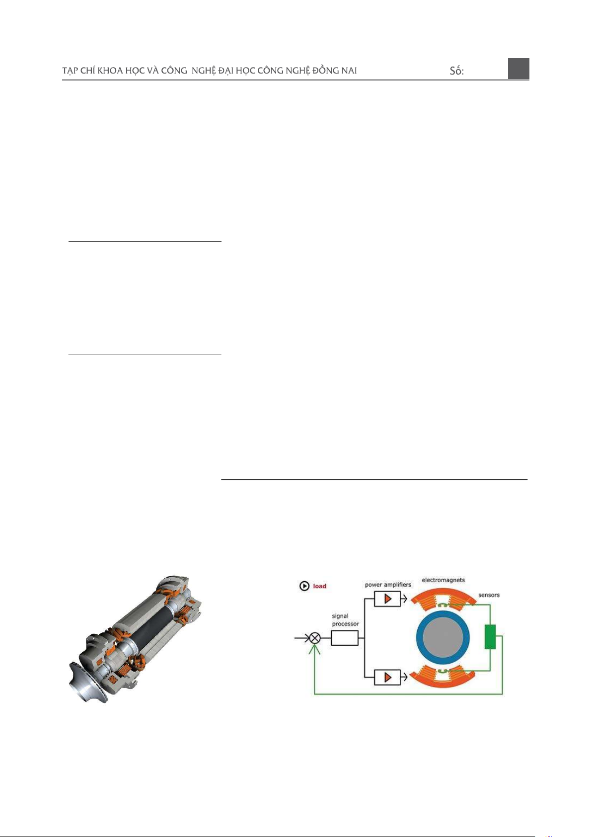
1. INTRODUCTION
Magnetic ball bearing systems are widely
applied in various fields in industry and some
aviation fields. Typically, high-speed
equipment such as motors with up to 60000
revolutions per minute, high-speed
compressors, turbines
(a) (b)
Figure 1. Application in turbocompressor (a) and magnetic ball bearing control principle (b)
01-2025
51
The advantages of magnetic ball bearings
are no need for lubricating oil, low noise, high
operating speed, no mechanical friction,...
Magnetic ball bearings are non-linear, unstable
systems so a relay system is required to
stabilize the system. The simple model of
magnetic ball bearing, is the voltage control or
current control model (H.Lee, V. Utkin et al.,
2007).
Advantages of magnetic ball bearings: -
Low friction force. - Can work at high speed. -
Application for places where high speed is
required. - No noise. - No vibration. - No need
for grease. Disadvantages of magnetic ball
bearings: - Difficult to control. - The price is
quite high. - Complex fabrication and
maintenance (Chien et al., 2009)
In practice, the use of magnetic ball
bearings can have more than one pole to
increase the efficiency in control. Similar to
the single-pole type, other types also develop
on the basis of a basic pole. The only
difference is that these poles are not in the
same direction but deviate from each other
depending on the number of poles designed to
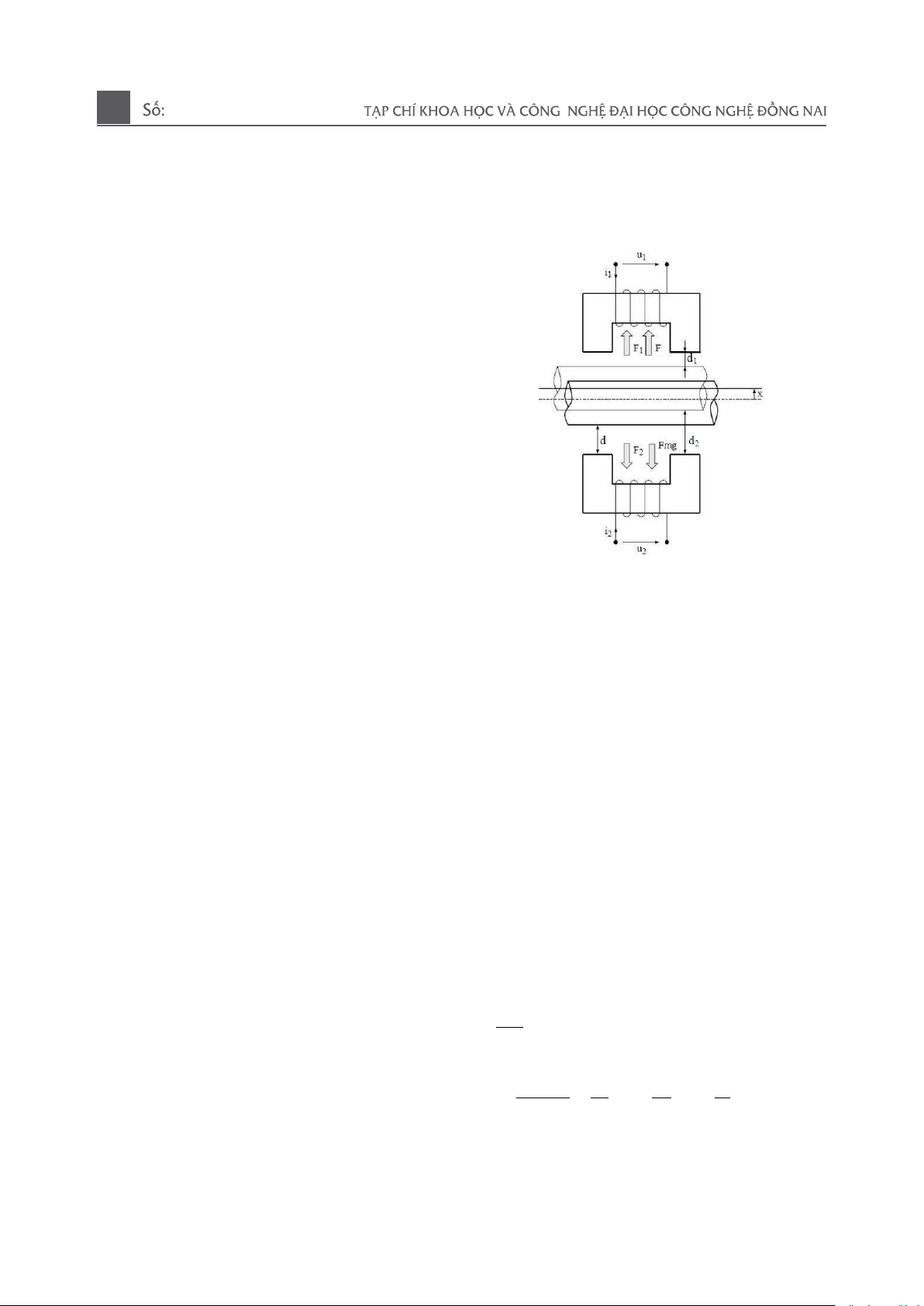
be used. The basic magnetic ball bearing
structure consists of: two coils wound on a
steel core placed opposite each other in the
middle of the ball bearing shaft (Rotor), with a
mass of m, between the two coils and the rotor
with an air gap (Abdul et al., 2008). Based on
the properties of the magnetic material and the
magnetic field generated by the current to
generate the force. When the two initial
currents i1 and i2 are applied to the two
electromagnets, two forces are generated that
depend on the current and the number of loops
on each coil. These two forces will act on the
rotor with two different force values in two
opposite directions, making the rotor shift in
the direction of stronger impact force.
Therefore, in order for the rotor to go to the
desired position, change either i1 or i2 or both
currents to create a magnetic field and create
another F1 and F2 force to translate the rotor
to the desired position. (Chien et al., 2009)
Figure 2. Mathematical Model of Magnetic
Ball Bearing System
2. METHODOLOGY
In order to keep the rotor in a balanced
position, we can apply current or voltage to the
two coils. Here, we control the current. When
two currents i1 and i2 are applied to two coils,
two forces will be generated that depend on
the current, the number of turns on each coil.
In the static or non-electrical state, the rotor
will be completely deviated towards the
electromagnet 2 (as shown in Figure 1.2), so
we have to control two different currents for
the two windings and also depend on the
external force acting on the rotor (H.Lee, V.
Utkin et al., 2007). We have the equation of
equilibrium force as follows:
2
1 2
2mg
dx
m F F F F
dt
= − + −
(1)
2 2
2
.0 1 2
2
1 2
1
4* s
N A i i
x F
m d d m
= − +
(2)
01-2025
52
2
2
0 1
1
1
4
N A i
Fd
=
(3)
2
2
0 2
2
2
4
N A i
Fd
=
(4)
F
s
= F - F
mg
We have the voltage equation of the
Electromagnet of the system
1 1
1 1
1
2
s
di i
K d
u Ri L dt dt d
= + +
(5)
2 2
2 2
2
2
s
di i
K d
u Ri L dt dt d
= + +
(6)
Equation of Balance of Force:
2
1 2
2mg
dx
m F F F F
dt
= − + −
(7)
2 2
2
.0 1 2
2
1 2
1
( ) 4*
s
N A i i
x t F
m d d m
= − +
(8)
With:
2
2
01
1
1
4
N A i
Fd
=
(9)
2
2
02
2
2
4
N A i
Fd
=
(10)
F
s
= F - F
mg
In which:
m: Rotor mass (Kg)
X: Air Clearance Variability (m)
D: Air gap at the balanced position (m)
v : Rotor displacement velocity (m/s)
μ0: magnosity (H/m)
A: Magnetic polar cross-section (m
2
)
N: Number of wire loops in each reel
i1: current through electromagnet coil 1 (A)
i2: current through electromagnet coil 2 (A)
F: Rotor Load Interference (N)
Fmg: Gravity
F1, F2: The force generated by the current i1
and i2 (N)
2
0
4*
N A
K
m
=
(11)
d
1
=d-x ; d
2
=d+x
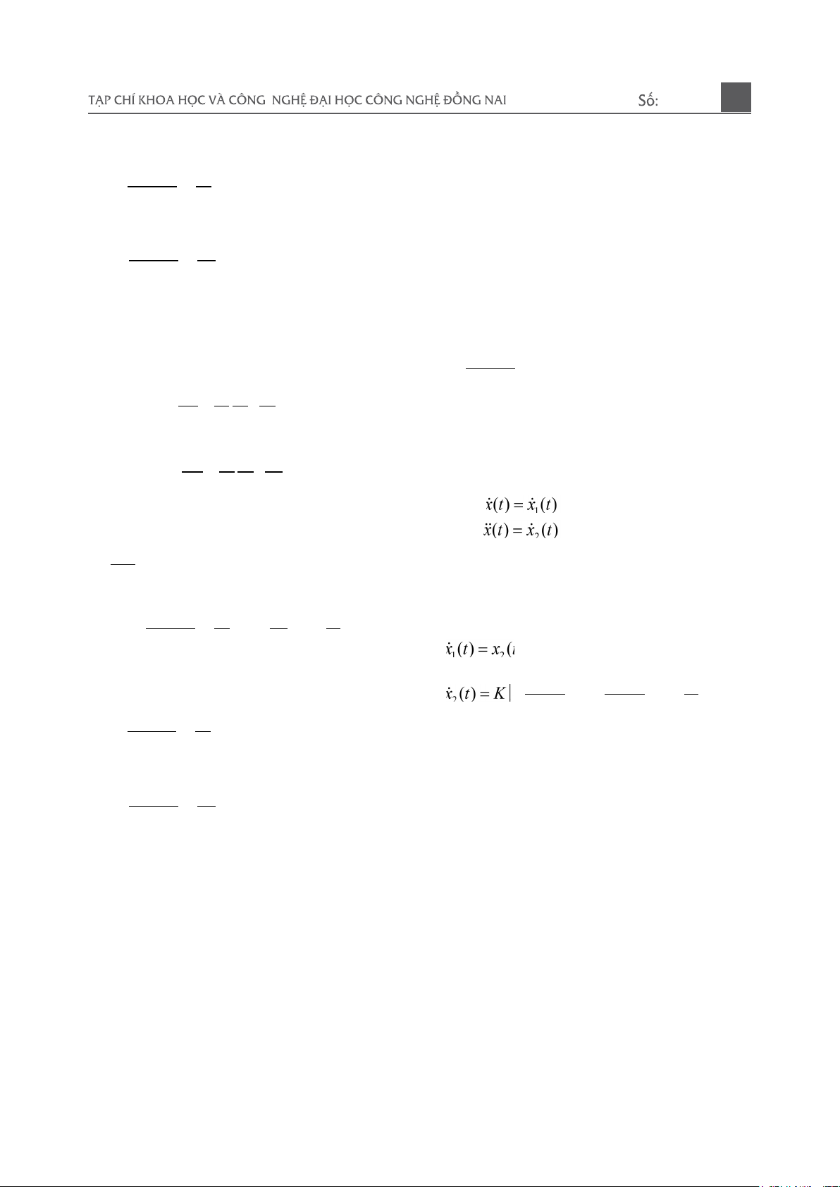
The selected state variables are as follows:
1
2 1
3 2
( ) ( )
( ) ( ) ( )
( ) ( ) ( )
x t x t
x t x t x t
x t x t x t
=
= =
= =
(12)
State variable equation of magnetic ball
bearing system:
1 2
2 2
1 2
2
1 1
1
( ) ( )
1
( )
( ) ( )
s
x t x t
i i
x t K F
d x d x m
x t x t
=
= − +
− +
=
(13)
The magnetic ball bearing control system
includes:
- Rotor with a mass of m = 6kg
- Two electromagnets are formed from loops
of wire wrapped around a steel core with coil
resistance R=10Ω
- Inductance L = 0.1H
- Number of wire loops N=600
- Air clearance at equilibrium d = 0.00053 m
- Pole cross section A = 0.000225 m
2
01-2025
53
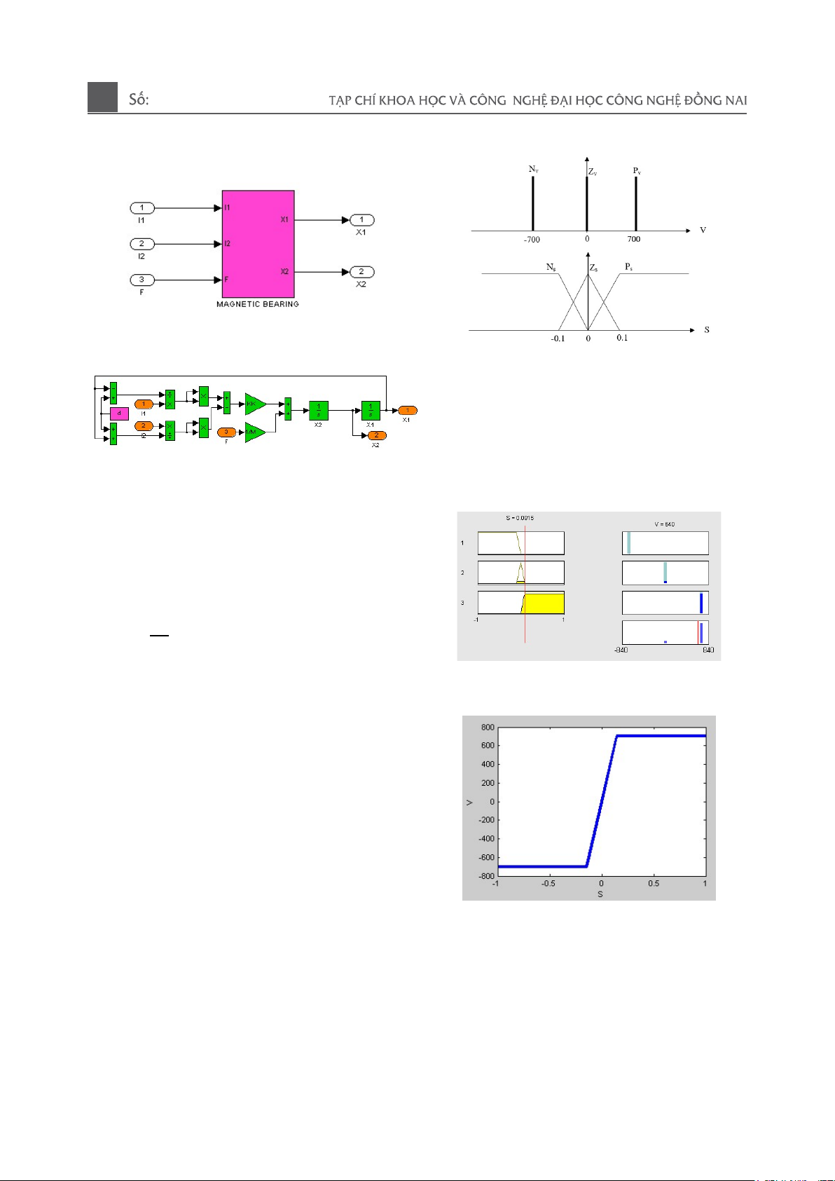
- Magnetic coefficient μ0 = 0.0000004*pi
Figure 3. Block diagram depicting the
magnetic ball bearing system
Figure 4. Simulation diagram of a magnetic
ball bearing system using Simulink/Matlab
3. BLUR SLIDE CONTROL
Design of translucent slip controller for
magnetic ball bearing system
We have the law of sliding control:
2
1
( ) ( ) ( )u t x t sign s
k
= − +
(14)
Since the sign(s) function causes chatting,
we change the component
sign(s) by matte
processing
Step 1: Identify the language variables in and
out
Input: S
Output:
( )v sign S
=
Step 2: Determine the fuzzy set for each in-out
variable
Language variables
S={negative, zero, positive}={Ns, Zs, Ps}
V={negative, zero, positive}={Vv, Zv, Pv}
Develop control laws Fuzzy control system
built according to Sugeno fuzzy law
-If S is Ns then v is Nv
- If S is Zs then v is Zv
-If S is Ps then v is Pv
Manifestation of the Amendment Law
Figure 5. Manifestation of the Amendment
Law
Figure 6: Developing Governing Laws
Step 3: Choose the constituent and
unambiguous law
- Choose the constituent law according to the
Min-Max rule
- Deblurring in the medium method
Sliding Dimming Controller Diagram”
01-2025
54
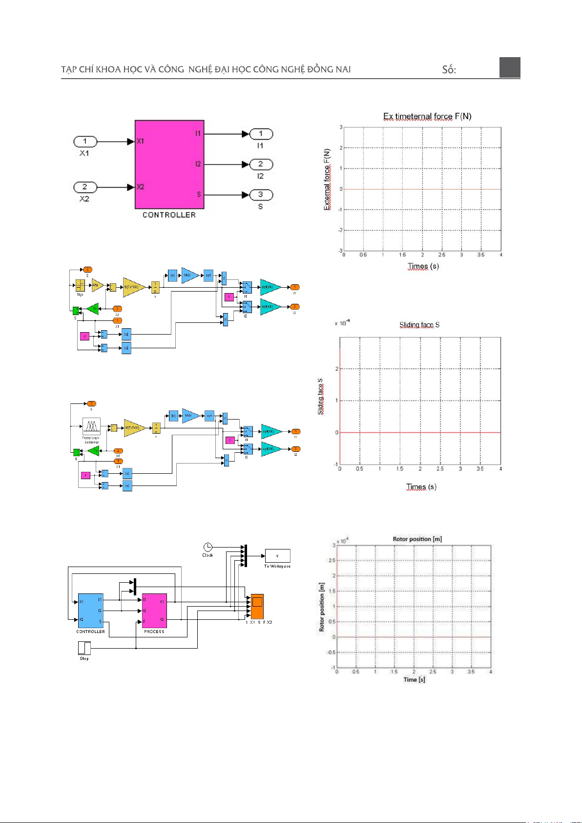
Figure 7. Block diagram depicting the slide
controller
Figure 8. Simulation diagram of a slide
controller using Simulink/Matlab
Figure 9. Simulation diagram of a fuzzy slip
controller using Simulink/Matlab
Figure 10. Diagram simulating the dim slip
controller of a magnetic ball bearing system
Simulation results:
Figure 11. External force acting on the sliding
surface
Figure 12. Sliding surface when there is no
external force
Figure 13: Rotor position when there is no
external force acting
01-2025
55


![Bài giảng Vi điều khiển Nguyễn Huy Hoàng: Tổng hợp kiến thức [Chuẩn nhất]](https://cdn.tailieu.vn/images/document/thumbnail/2026/20260316/hoatrami2026/135x160/72211773806757.jpg)


![Bài giảng Tự động hoá thiết bị điện [chuẩn nhất]](https://cdn.tailieu.vn/images/document/thumbnail/2026/20260312/hoabattu2026/135x160/61691773631881.jpg)
