
Designing optimal material selection for manufacturing car
wheel rims
Thiết kế lựa chọn vật liệu tối ưu cho việc chế tạo mâm bánh xe ô tô
Van Tinh Nguyen1, Tuan Kiet Vo2, Cao Hieu Le1, Van Cuong Le3
1Nguyen Tat Thanh University, Ho Chi Minh city
2Thu Dau Mot University, Binh Duong
3Binh Duong University. Binh Duong
Corresponding author: Van Tinh Nguyen. E-mail: vantinh.gv@gmail.com
Abstract: The selection of suitable material for manufacturing wheel rim is essential to
address the issue of weight reduction while ensuring the load-bearing capacity of the wheel
rims during vehicle movement on the road. In this study, the research team designed a 3D
model of the wheel rim using Solidworks software. Afterwards, a numerical simulation
model using Ansys Workbench software was constructed to calculate the load-bearing
capacity of the wheel rim under two conditions: stationary and moving, using four different
materials including steel alloy, aluminum alloy, magnesium alloy, and titanium. From the
calculated results, the research team concluded that aluminum remains a suitable material
for manufacturing wheel rims. This is due to its appropriate mechanical properties, ease of
fabrication, cost-effectiveness, and the significant weight reduction achieved when wheel
rims are manufactured using aluminum material.
Keywords: Wheel rim, numerical simulation, steel alloy, aluminum alloy, magnesium
alloy, titanium.
Tóm tắt: Việc lựa chọn vật liệu phù hợp cho việc chế tạo mâm bánh xe là yếu tố quan
trọng để giảm trọng lượng đồng thời đảm bảo khả năng chịu tải trong quá trình xe vận hành
trên đường. Nghiên cứu này tập trung vào việc thiết kế một mô hình 3D của mâm xe với
phần mềm Solidworks và xây dựng một mô hình mô phỏng số với phầm mềm Ansys
Workbench để đánh giá khả năng chịu tải dưới trong hai trường họp với điều kiện xe đứng
yên và di chuyển. Bốn vật liệu gồm hợp kim thép, hợp kim nhôm, hợp kim magiê và titan
đã được tính toán và đánh giá kết quả mô phỏng. Kết quả chỉ ra rằng nhôm vẫn là vật liệu
phù hợp nhất do tính chất cơ học phù hợp, dễ gia công và hiệu quả về chi phí, và đạt được
sự giảm trọng lượng đáng kể cho mâm xe khi mâm bánh xe được chế tạo bằng vật liệu
nhôm.
Từ khóa: Mâm bánh xe, mô phỏng số, hợp kim thép, hợp kim nhôm, hợp kim magiê, titan.
1. Introduction
The wheel rim is a load-bearing rotating
component. The tire is mounted on the
outside of the wheel rim and situated
between the vehicle's axles. Its function
is to securely attach the tire to the vehicle
while transmitting and bearing various
types of forces and moments between the
tire and the vehicle's axle. The wheel
comprises the rim, hub, and spokes.
Commonly used materials for
manufacturing wheels nowadays include
aluminum alloy and steel, with
magnesium alloy and titanium alloy
being introduced later. Based on current
manufacturing technologies, wheels can
be made using various methods such as
stamping, welding, casting, or forging.
Being a structure subjected to large
loads and harsh environments, wheel
rims must be designed to withstand high
loads with a high safety factor; however,
current trends are optimizing wheel rims
for weight reduction to achieve lighter
Tạp chí khoa học và công nghệ - Trường Đại học Bình Dương – Quyển 7, số 1/2024
Journal of Science and Technology – Binh Duong University – Vol.7, No.1/2024
139
https://doi.org./10.56097/binhduonguniversityjournalofscienceandtechnology.v7i1.221
weights. Therefore, to meet these
criteria, wheel rims are aimed to be
manufactured from optimized materials
that still ensure load-bearing capacity in
harsh working environments while
having overall lighter weight. In this
study, the research team applied
numerical simulation models under the
same boundary conditions for four
different types of materials to find the
most suitable material for manufacturing
optimized wheel rims.
In this study, Solidworks was utilized
in designing the 3D wheel rim and
numerical simulation models were
conducted with mesh models and
boundary conditions in two situations:
when the vehicle is stationary and when
it is moving on the road. Along with the
computational conditions, the research
team applied four types of materials:
aluminum alloy, steel alloy, magnesium
alloy, and titanium. The aim was to find
the most suitable material for the load-
bearing structure of the wheel rim and to
reduce its weight.
2. Design of wheel rim
Solidworks is a powerful tool in 3D
design, thus it has been utilized in this
study to create the wheel rim model. The
rim specifications were carefully
calculated and selected to align with
commercial products, ensuring accuracy
prior to simulation. The ongoing trend in
wheel design heavily emphasizes weight
reduction through material substitution,
mass reduction, and structural
optimization. Despite the complex
loading conditions and high-stress
environments experienced during
vehicle operation, lightweight design
remains a top priority. Nevertheless, it
also guarantees compliance with
industrial standards and achieves
exceptional load-bearing capacity.
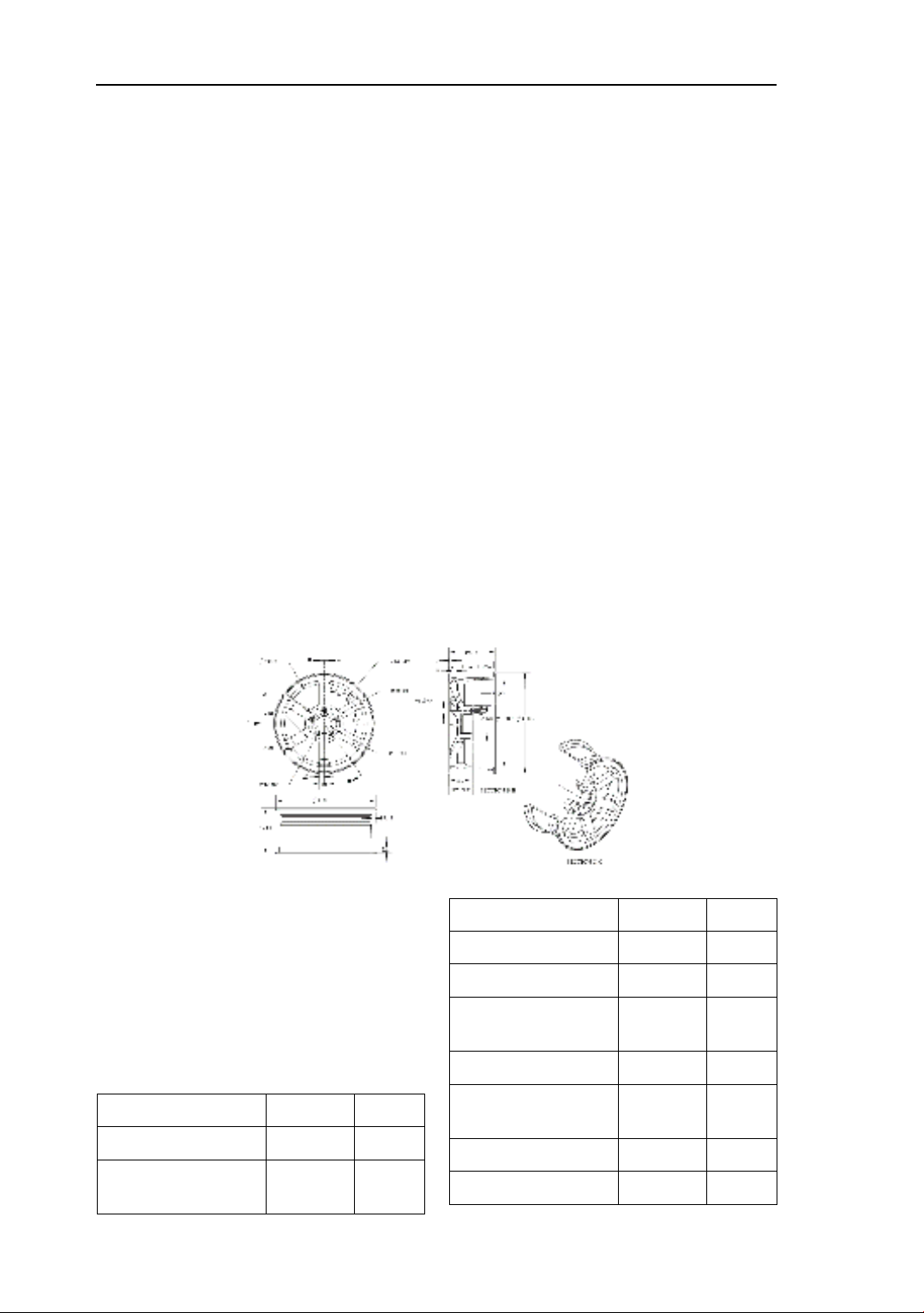
Figure 1. 03 projections of the wheel rim
Figure 1. presents detailed
specifications of the wheel rim, with all
units measured in millimeters.
Meanwhile, Table 1. displays the
computed values derived from the
wheel rim calculation basis.
Table 1. Technical specifications table of
the wheel rim.
Content
Value
Unit
Type of tire
Radial
-
Type of wheel
Disc
type -
Type of rim
Casting
-
Rim diameter
418.8
mm
Wheel width
193.8
mm
Diameter of the
bonding surface 148 mm
Bolt hole diameter
14
mm
Diameter of the bolt
hole seating surface 105.1 mm
Number of spokes
6
-
Spoke width
40
mm
140
Designing optimal material selection for manufacturing car wheel rims

3. Material and boundary conditions
in calculation
3.1. Material
Four common types of materials
commonly used for wheel rims are
aluminum alloy, steel alloy, magnesium
alloy, and titanium. The properties of the
04 aforementioned types of materials are
presented in Table 2 [1]. In which, the
weight of the wheel rim corresponding to
magnesium alloy is the lightest at 6.9kg,
aluminum alloy is 11.1kg, titanium is
19kg, and the heaviest is steel alloy at
31.6kg. Furthermore, aluminum alloy
stands out for its cost-effectiveness
compared to other materials. Not only
does it boast excellent resistance to
corrosion, but its ease of machining and
fabrication makes it a preferred choice
for a wide range of vehicles [2].
Table 2. Specifications of materials commonly used for wheel rims.
Material
Aluminum
alloy
Steel
alloy
Magnesium
alloy
Titanium Unit
Young modulus 7.00E+10 2.00E+11 4.48E+10 1.14E+11 Pa
Poisson ratio
0.346
0.266
0.35
0.34
-
Density 2710 7860 1798 4460 kg/m3
Thermal
expansion
2.36E-05 1.17E-05 2.88E-05 9.50E-06 0K
Yield strength
0.95E+08
2.50E+08
2.75E+08
8.25E+08
Pa
3.2. Boundary conditions in
calculations
a)The load on the wheel rim is calculated
when the vehicle is stationary
In the case of the vehicle being stationary
on a level road, one wheel rim is mainly
influenced by tire pressure and 1/4 of the
vehicle's weight if the vehicle's center of
gravity is between the two axles. But in
the case where the vehicle is stationary
while turning uphill at the tipping angle
of the vehicle, one rear wheel rim bears
half of the entire vehicle's load [3].
Total weight of the vehicle: 2500 kg
Load placed on the rear wheel rim when
the vehicle is stationary turning uphill at
the tipping angle: 2500/2 = 1250 kg
The force applied on the rear wheel:
1250 × 9.81 = 12262.5 N
The maximum tire pressure exerted on
the wheel rim: 40 × 6894 = 0.27576 MPa
b) The load acting on the wheel rim when
the vehicle is in motion
When a vehicle moves on a flat road,
besides the pressure exerted by the tires,
the weight of the vehicle is placed on
each wheel; the wheel rim also
experiences additional torque from the
engine along with the engine speed
transmitted [3]. Table 3. presents the
calculated parameters for the wheel rim
load-bearing capacity in the case where
the vehicle moves through the theoretical
calculation basis.
Table 3. Calculated parameters of the
wheel rim in the moving vehicle condition
Maximum torque of
the engine 260 Nm
Engine speed at
maximum torque 2400 rpm
Power at maximum
torque of the engine 65 kW
Torque at the wheel
output shaft 1497.37 Nm
Total vehicle weight
2500.00 kg
141
Van Tinh Nguyen, Tuan Kiet Vo, Cao Hieu Le, Van Cuong Le
Load placed on each
wheel 625 kg
Force applied to each
wheel 6131.25 N
Maximum tire
pressure acting on the
wheel rim
275760 Pa
4. Numerical Simulation and Results
4.1. Numerical Simulation
a) Stationary vehicle on slope at
vehicle's rollover angle
After selecting the material and
importing the 3D Solidworks model of
the wheel rim into Ansys Workbench in
the "Geometry" dialog box, the next step
is to set up the mesh in the "Model"
dialog box, as finite element method is
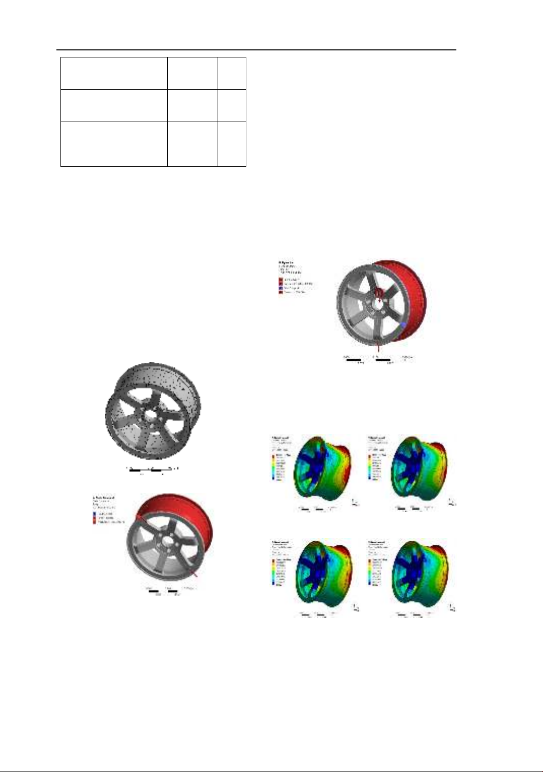
used in this problem [4], [5]. Figure 2a
illustrates the mesh model of the
component.
Figure 2a. Mesh model of the wheel rim
Figure 2b. Boundary conditions
Next, the fixed constraints on the surface
of the bolt hole and the component acting
on the rim are illustrated in Figure 2b.
The selection of these fixed positions is
based on the surface of the bolt hole
contacting the center of the rivet in the
actual state [3], [6].
b) Case when the vehicle is moving on
the road
The steps of material selection, model
placement, and mesh generation are
repeated as in the static case. Through
calculations, the boundary conditions
have been established and are illustrated
as shown in Figure 3. In addition to
bearing loads from the vehicle, the
surfaces of the bolt holes also experience
additional shear moments from the bolts
as the vehicle moves, while the fixed
positions are placed on the wheel rim [3],
[6].
Figure 3. Force application model when
4.2. Simulation Results
a) Results when the vehicle is
stationary
a b
c d
Figure 4. Total deformation of the wheel
rim under stationary vehicle conditions
with materials a) Aluminum alloy, b) Steel
alloy, c) Magnesium alloy, d) Titanium.
142
Designing optimal material selection for manufacturing car wheel rims
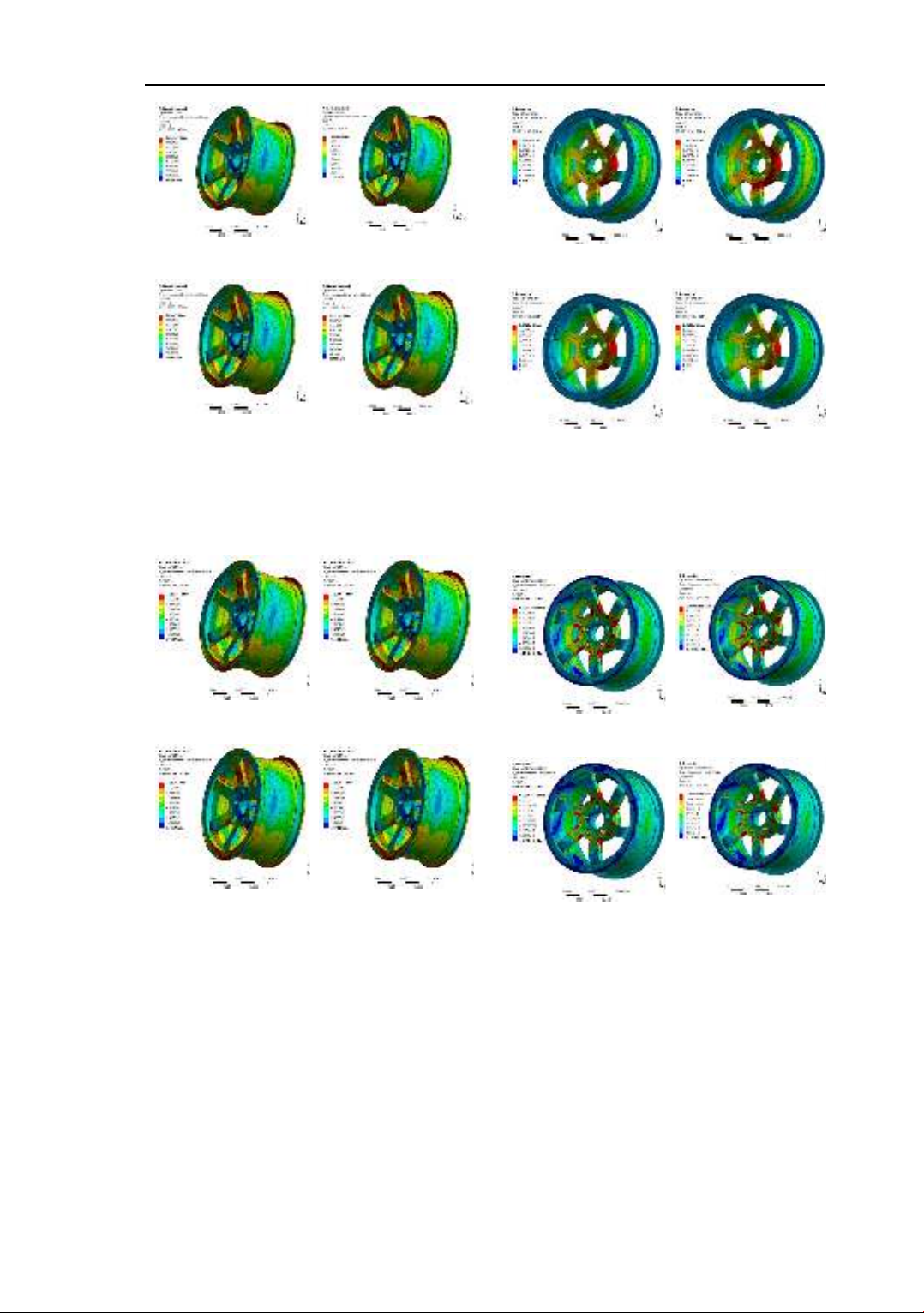
a b
c d
Figure 5. Results of Equivalent Elastic
Strain under stationary vehicle conditions
with materials a) Aluminum alloy, b) Steel
alloy, c) Magnesium alloy, d) Titanium.
a b
c d
Figure 6. Results of Equivalent Stress
under stationary vehicle conditions with
materials a) Aluminum alloy, b) Steel alloy,
c) Magnesium alloy, d) Titanium.
b) Simulation Results in the Case of
Vehicle Movement
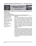
a b
c d
Figure 7. Total deformation of the wheel
rim in the case of a moving vehicle with
materials a) Aluminum alloy, b) Steel alloy,
c) Magnesium alloy, d) Titanium.
a b
c d
Figure 8. Results of Equivalent Elastic
Strain in the case of a moving vehicle with
materials a) Aluminum alloy, b) Steel alloy,
c) Magnesium alloy, d) Titanium.
143
Van Tinh Nguyen, Tuan Kiet Vo, Cao Hieu Le, Van Cuong Le
![Tài liệu đặc tính kỹ thuật dây đồng trần xoắn [C] chuẩn nhất](https://cdn.tailieu.vn/images/document/thumbnail/2025/20250808/trinhvanmotnt@gmail.com/135x160/21161754899208.jpg)


![Giáo trình Vật liệu cơ khí [mới nhất]](https://cdn.tailieu.vn/images/document/thumbnail/2025/20250909/oursky06/135x160/39741768921429.jpg)


