
TNU Journal of Science and Technology
229(06): 140 - 148
http://jst.tnu.edu.vn 140 Email: jst@tnu.edu.vn
SEISMIC ANALYSIS OF AN OFFSHORE WIND TURBINE
ON THE MONOPOLE FOUNDATION USING THE TWO-STEP METHOD
Huynh Van Quan*, Le Huu Dat
Campus in Ho Chi Minh City, University of Transport and Communications
ARTICLE INFO
ABSTRACT
Received:
15/02/2024
This study employs a two-step method to examine the seismic response
of offshore wind turbine (OWT) systems supported by monopile
foundations. In the first step, the soil-monopile interaction (SMI) is
simulated using the professional software program OpenSeesPL. In the
second step, the OWT structure is simulated employing the lumped-
parameter method (LMP). The response of the OWT structure is then
analyzed using the results from the first step with a single degree of
freedom (DOF). An OWT with a capacity of 5 MW is studied
numerically. Three different soil profiles are analyzed, and the effects
of ignoring soil-structure interaction (SSI) using fixed-base models are
investigated. In comparison to the fixed-base model, the SMI increases
the peak acceleration values of monopile tops: the ratios for dense sand,
stiff clay, and multiple strata are 3.68, 2.62, and 2.58, respectively.
Peak absolute displacements in the SSI model at the top of the tower
are 10-20 times higher than those in a fixed-base model, and the SMI
significantly contributes to absolute displacements.
Revised:
14/5/2024
Published:
14/5/2024
KEYWORDS
Offshore wind turbine
Monopile foundation
Seismic analysis
Two-step method
OpenSeesPL
PHÂN TÍCH TRỤ ĐIỆN GIÓ XA BỜ ĐẶT TRÊN MÓNG CỌC ĐƠN
CHỊU ĐỘNG ĐẤT BẰNG PHƯƠNG PHÁP HAI BƯỚC
Huỳnh Văn Quân*, Lê Hữu Đạt
Phân hiệu tại Thành phố Hồ Chí Minh, Trường Đại học Giao thông vận tải
THÔNG TIN BÀI BÁO
TÓM TẮT
Ngày nhận bài:
15/02/2024
Nghiên cứu này áp dụng phương pháp hai bước để khảo sát phản ứng
của trụ điện gió ngoài khơi (OWT) đặt trên móng cọc đơn chịu tải trọng
động đất. Trong bước một, tương tác giữa đất nền và móng được mô
phỏng bằng phần mềm chuyên dụng OpenSeesPL. Bước thứ hai, hệ
OWT được mô phỏng bằng phương pháp tham số tập trung. Trong phân
tích, hệ OWT được mô hình thành một bậc tự do chịu kích thích nền là
kết quả của bước một. Bài báo phân tích số đối với công trình OWT có
công suất 5 MW. Ba môi trường đất đặt móng khác nhau được khảo sát
và ảnh hưởng của việc bỏ qua tương tác kết cấu-đất nền đã được xem
xét. So với mô hình cố định, tương tác giữa đất nền và móng (SFI) đã
làm tăng giá trị gia tốc đỉnh móng. Tỷ lệ tăng tương ứng đối với cát
chặt, sét cứng và đất nhiều lớp lần lượt là 3,68, 2,62 và 2,58. Việc xét
đến SFI làm cho chuyển vị tuyệt đối của đỉnh tháp cao hơn 10-20 lần so
với mô hình cố định. Trong đó, chuyển vị của hệ đất nền-móng đóng
góp phần lớn vào giá trị chuyển vị tuyệt đối của đỉnh tháp.
Ngày hoàn thiện:
14/5/2024
Ngày đăng:
14/5/2024
TỪ KHÓA
Trụ điện gió xa bờ
Móng cọc đơn
Phân tích động đất
Phương pháp hai bước
OpenSeesPL
DOI: https://doi.org/10.34238/tnu-jst.9704
* Corresponding author. Email: quanhv_ph@utc.edu.vn
TNU Journal of Science and Technology
229(06): 140 - 148
http://jst.tnu.edu.vn 141 Email: jst@tnu.edu.vn
1. Introduction
Wind energy sources are becoming more and more widespread worldwide. In Vietnam,
onshore wind farms like those in Quang Tri, Dak Nong, and Ninh Thuan provinces are highly
popular. Offshore wind farms like Ben Tre, Bac Lieu, Ca Mau, and other provinces have grown
over time [1], [2]. Onshore wind turbine foundations are relatively easy to design and build
because they are standardized and well-known to civil engineers. On the other hand, because they
have to match the seabed's soil and the sea level's depth, the foundations of OWTs have special
characteristics and are extremely complex. Sea reclamation projects to construct OWTs have
become very important due to future demands [3].
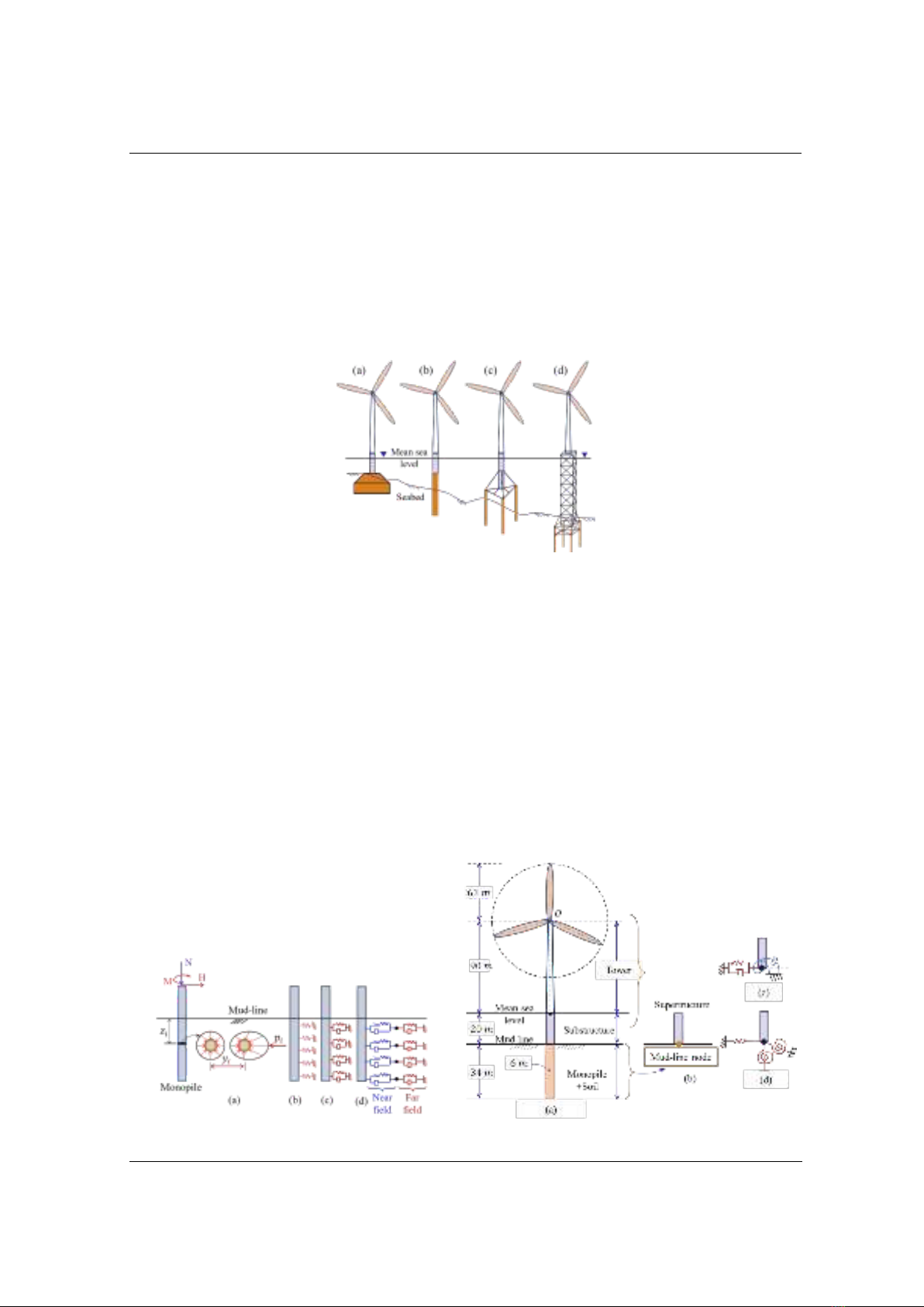
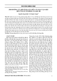
Figure 1. Options for OWT's foundation, (a): gravity, (b): monopile, (c): tripod, (d): jacket
According to Gasch [4], foundation work accounts for 20 to 30 percent of a wind power
project's overall cost. Due to the high cost, it is important to select a foundation that suits the
actual conditions. For OWTs, a variety of foundation types have been employed, such as gravity,
monopile, tripod, and jacket foundations (see Figure 1) [5]. The most common foundation type,
monopile foundations, not only offer cost efficiencies but also guarantee operational safety.
According to Oh [6], a significant 91% of projects implemented in 2014 employed monopile
foundations. Forecasts indicate that between 50 and 60 percent of OWTs will be built with
monopile foundations by 2020 [7]. For example, a 5 MW OWT installed in the North Sea was
reported by [8] to have a tower height of 95 m above mean sea level and a rotor diameter of 125
m. The corresponding static forces of wave and wind in an OWT at the seabed were 4 MNm for
torsional moments, 35 MNm for axial loads, and 16 MN for horizontal loads. These numbers
demonstrate that in order for the monopile to respond to an external force, it must produce an
extremely high resistance. For this reason, researching OWTs with monopile foundations is
highly helpful.
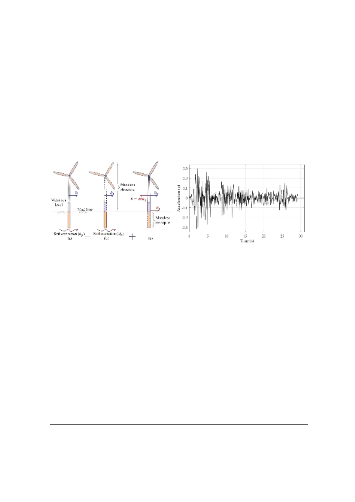
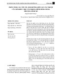
Figure 2. P-y curve models [9], [10]
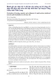
Figure 3. Sway-rocking models [11], [12]

TNU Journal of Science and Technology
229(06): 140 - 148
http://jst.tnu.edu.vn 142 Email: jst@tnu.edu.vn
A brief summary of two popular LMP for monopile foundations can be found in Figures 2 and
3. P-y curve method (refer to Figure 2(a)) divides the soil-monopile system into smaller elements.
All elements of the monopile are connected to the ground along its length by either a soil spring
(refer to Figure 2(b)); a couple of springs and dampers (refer to Figure 2(c)); or, in a more
complex connection, a division of the surrounding soil into near and far fields (refer to Figure
2(d)) [9], [10]. The monopile and soil systems' responses are replaced in sway-rocking methods
by a mud-line node at the seabed (see Figure 3(a)). The mud-line node, as seen in Figure 3(b,c),
has six DOFs in the spartial model but only basic DOFs in the plane model [11], [12]. The
difficulty in simulating the nonlinearities of SMI is the LMP's limitation.
In the finite-element method (FEM), the authors used ABAQUS [13] or FAST software [11]
to model and calculate the OWT responses. In these models, a significant amount of simulation
and computation will be needed to model the entire OWT system (soil, foundation, substructure,
tower, hub, rotor, nacelle,...).
In seismic analysis of an OWT, the SMI is complicated, while we aim to obtain the specific
responses of the OWT superstructure. Consequently, it will be very helpful to reduce
computations if SMI and tower structure can be modeled separately. The suggestion is then that
the tower structure should be simulated by the LMP and the SMI by the FEM. This analysis
process is consistent with the suggestion that SSI problems be solved using Kausel's
superposition method (two-step method) [14] - [16].
This paper employs the two-step method for seismic analysis of the soil, monopile foundation,
and OWT systems. By including the SMI, the analysis results are more in line with the real
behavior. The first step of this method is to analyze the SMI using OpenSeesPL. In the second
step, the tower structure at its base is excited using the accelerations from the first step. In order
to simulate the tower, the system of hub, nacelle, and blades are combined into a single lump at
hub height. Meanwhile, the tower, which is a massless structure, is modeled using an Euler-
Bernoulli beam model. In the numerical calculation, the SMI examines homogeneous soil of
dense sand and stiff clay, multiple strata; the monopile length is 34 m, and the OWT has a
capacity of 5 MW. The analytical results are compared to the fixed-base model.
2. The two-step method to OWT seismic analysis
The paper proposes solving the SSI problem of an entire OWT system in two steps using
Kausel's method [14] - [16] (see Figure 4). The SMI under seismic load (Figure 4(a)) is analyzed
by matrix equation (2) in the first step, which ignores the mass of the structure (Figure 4(b)). The
acceleration at the top of the monopile foundation is obtained in this step, which causes the
structure to vibrate in the second step. In order to obtain the responses from the OWT system
(Figure 4(c)), the analysis process in the second step is performed using matrix equation (2). In
seismic analysis, the first and second steps are referred to as kinematic and inertial interactions,
respectively. Matrix equation (3), which is the product of matrix equations (1) and (2), serves as
the general equation of motion for the analysis of the entire OWT system.
(1)
(2)
(3)
where the relative and absolute displacement vectors of the foundation are denoted by ( );
the relative displacement vector of the structure is denoted by ; the ground motion vector is
denoted by ; the mass of the soil matrice is omitted by , while the mass matrice of the
structure is omitted by ; , , , and ; the
absolute and relative displacement vectors are represented by and , respectively; and the
mass, damping, and stiffness matrices of the entire system are denoted by , and . The
equations (1)-(3) have displacement vectors ( ) with size ; and matrices of
TNU Journal of Science and Technology
229(06): 140 - 148
http://jst.tnu.edu.vn 143 Email: jst@tnu.edu.vn
mass ( ), stiffness ( ), and damping ( ) with size ; where is the DOF number
of the entire OWT system. It should be noted that corresponding elements in vectors ( )
and matrices ( ) will have zero values if any mass of DOF is ignored.
Using a finite element tool is recommended for the first step, as per [14] – [16]. At the present
time, a number of commercial programs, including ABAQUS, ANSYS, PLAXIS, and others, can
perform SFI due to advances in computer software. A free finite-element software called
OpenSeesPL was created by the Pacific Earthquake Engineering Research Center (University of
California) to analyze the lateral 3D ground-pile interaction [17]. It is an effective technique to
analyze nolinear SMI under earthquake loads. OpenSeesPL supplies pushover, mode shape, and
base input acceleration analysis as available analysis options. More information about the
program can be found in the OpenSeesPL user manual. In this paper, a SMI is simulated with
OpenSeesPL; the OWT tower system is modeled by either a single DOF system (if tower mass is
ignored) or a multi-DOF system [18].
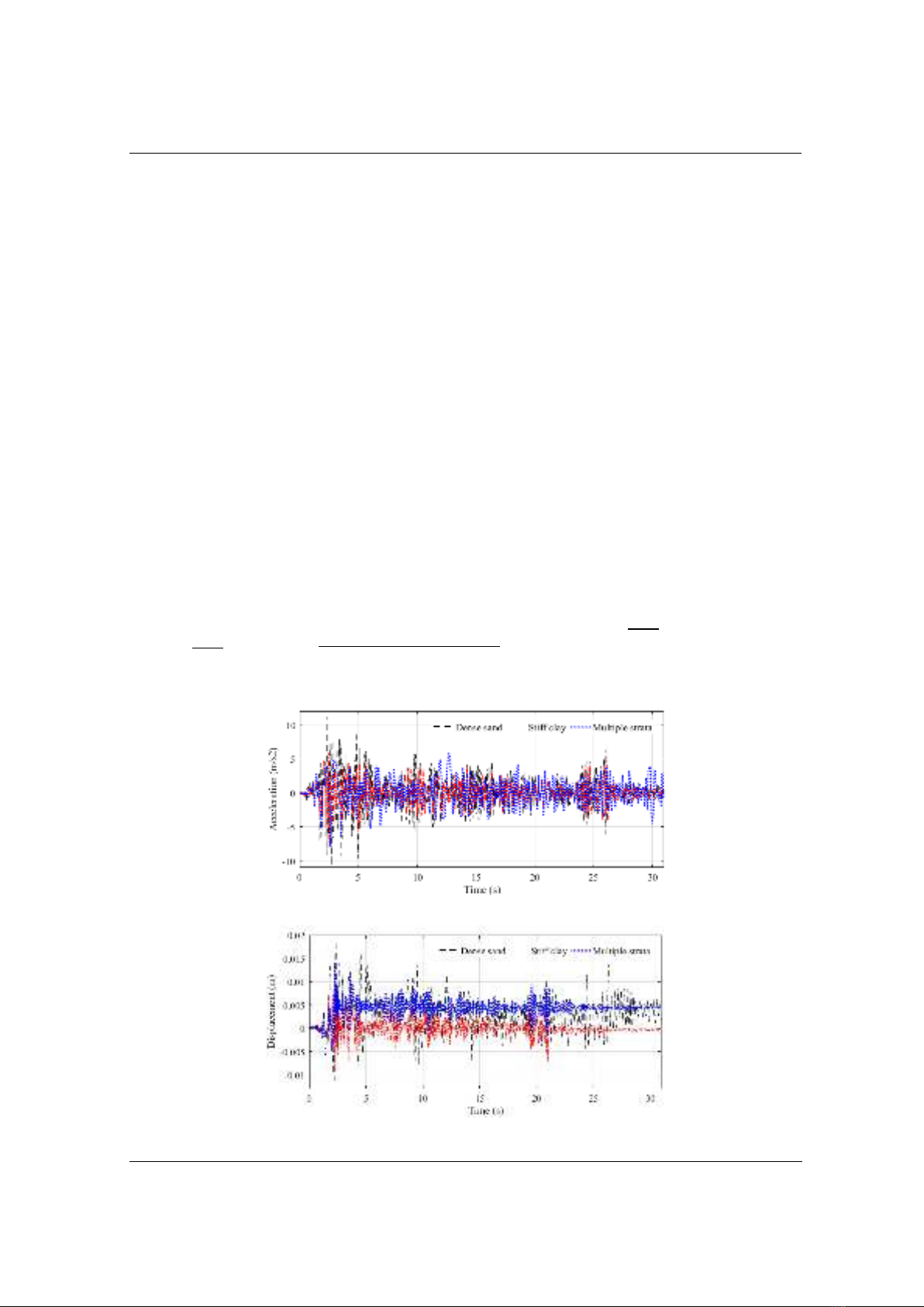
Figure 4. (a): the complete solution, (b): the
first step, and (c): the second step
Figure 5. Acceleration of the El Centro (1940)
earthquake [21]
3. Numerical studies and discussion
3.1. Description
This study examines a 5-MW OWT using the model shown in Figure 3(a). The hub diameter
is 3 m, the hub height is 90 m, and the rotor diameter with three blades measures 126 m. The
mass of the tower is 347 tons, the nacelle is 24 tons, and the rotor is 110 tons. It is assumed that
the tower and substructure were modeled with constant dimensions of 6 m in diameter and 0.019
m in thickness. The monopile has a diameter of 6.0 meters, a wall thickness of 0.09 meters, and
an embedment depth of 34 meters into the soil strata [19], [20]. The tower and substructure were
defined by linear elastic material properties and elastic Euler-Bernoulli beam elements. The
monopile foundation is placed on three different soil types (Cases 1-3) with a 66-meter soil
depth. The soils in Cases 1 and 2 are homogeneous, composed of stiff clay and dense sand. Case
3 has multiple strata arranged as follows: 6 m-dense sand, 10 m-medium clay, and 50 m-stiff
clay. Table 1 lists the predefined parameters for different soils. The longitudinal El Centro (1940)
[21] with in PGA and m/s2 is the input motion (
); see Figure 5.
Table 1. Parameter values of soils [17]
Soil type
Shear wave
velocity (m/s)
Friction angle/ Undrained shear
strength (kPa)
Possion's
ratio
Mass density
(kg/m3)
Dense sand
255
40.0o
0.4
2.1103
Medium clay
200
37.0
0.4
1.5103
Stiff clay
300
75.0
0.4
1.8103
TNU Journal of Science and Technology
229(06): 140 - 148
http://jst.tnu.edu.vn 144 Email: jst@tnu.edu.vn
3.2. Analysis technique
As previously indicated, the OpenSeesPL program is employed for performing the seismic
analysis of SMI in the first step. The seismic analysis of the SMI involves three steps. The model
parameters, material properties, and mesh parameters of the soil and pile strata are defined in the
step 1. There is a menu with 18 predefined cohesionless and cohesive soil materials that users can
choose from. In addition, OpenseesPL allows users to define the properties of sand and clay. In
this study, the default properties of the predefined soils from OpenSeesPL were applied, see
Table 1. Rayleigh damping, plastic material, and an 8-node brick element were employed to
simulate the soils. For boundary conditions, rigid bedrock and rigid box types were selected. In
step 2, the paper chose the option for a single motion analysis. El Centro (1940) in Figure 5,
which has a longitudinal direction and a scale factor of 1.0, is the time-history acceleration of the
input motion. Step 3 performs finite element analysis to get the acceleration of the structure base
(the top of the monopile, ); these results are presented in Section 3.3.
The OWT model used in this study has a single DOF, and the mass of the blades and rotor-
nacelle is combined to equal 350 tons at the top of the tower model. The substructure and tower
mass are neglected, and the blades are not modeled [20]. Elastic Euler-Bernoulli beam elements
with linear elastic material properties and a structural Rayleigh damping assumption of ξ=1.0%
were applied to model the tower and substructure [22]. The vector form of equation (2) in the
second step, which matches to the single DOF of an OWT system, is as follows:
(4)
where the mass of the rotor-nacelle and blades kg,
flexural stiffness of Nm2 [23], hub height m, substructure height
m, monopile tower total length m,
N/m,
√ √( )( ) Ns/m.
3.3. The first step results: responses of soil-monopile system
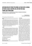
Figure 6. The accelerations ( ) of the monopile top with different soil profile
Figure 7. The displacements ( ) of the monopile top with different soil profile


![Bài giảng Quản lý vận hành và bảo trì công trình xây dựng [chuẩn nhất]](https://cdn.tailieu.vn/images/document/thumbnail/2025/20251006/agonars97/135x160/30881759736164.jpg)