
CHAPTER
27
ROLLING-CONTACT
BEARINGS
Charles
R.
Mischke,
Ph.D.,
RE.
Professor
Emeritus
of
Mechanical
Engineering
Iowa
State
University
Ames,
Iowa
21A
INTRODUCTION
/
27.2
27.2 LOAD-LIFE RELATION
FOR
CONSTANT RELIABILITY
/
27.7
27.3 SURVIVAL RELATION
AT
STEADY LOAD
/
27.8
27.4 RELATING
LOAD,
LIFE,
AND
RELIABILITY GOAL
/
27.9
27.5 COMBINED RADIAL
AND
THRUST LOADINGS
/
27.12
27.6 APPLICATION FACTORS
/
27.13
27.7 VARIABLE LOADING
/
27.13
27.8
MISALIGNMENT
/
27.16
REFERENCES
/
27.17
GLOSSARY
OF
SYMBOLS
a
Exponents;
a
=
3 for
ball bearings;
a =
10A
for
roller bearings
AF
Application
factor
b
Weibull shape parameter
C5
Static load rating
C10
Basic load rating
or
basic dynamic load rating
/
Fraction
F
Load
Fa
Axial load
Feq
Equivalent radial load
F1
/th
equivalent radial load
Fr
Radial load
/
Integral
L
Life measure,
r or h
LD
Desired
or
design
life
measure
LR
Rating
life
measure
L10
Life
measure exceeded
by 90
percent
of
bearings tested

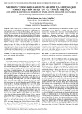
FIGURE
27.1 Photograph
of a
deep-groove preci-
sion
ball bearing
with
metal two-piece cage
and
dual
seals
to
illustrate
rolling-bearing
terminology. (The
Bar
den
Corporation.)
n
Design factor
nD
Desired
or
design rotative speed,
r/min
HI
Application
or
design factor
at
/th
level
nR
Rating rotative speed, r/min
R
Reliability
V
Rotation factor; inner ring rotations,
V=I;
outer ring,
V =
1.20
x
Life measure
in
Weibull survival equation
Jc0
Weibull guaranteed
life
parameter
X
Radial factor
for
equivalent load prediction
Y
Thrust factor
for
equivalent load prediction
0
Weibull characteristic
life
parameter, rotation angle
$
Period
of
cyclic variation,
rad
27.7 INTRODUCTION
Figures 27.1
to
27.12 illustrate something
of the
terminology
and the
wide variety
of
rolling-contact bearings available
to the
designer. Catalogs
and
engineering manuals
can
be
obtained
from
bearing manufacturers,
and
these
are
very comprehensive
and
of
excellent quality.
In
addition, most manufacturers
are
anxious
to
advise designers
on
specific applications.
For
this reason
the
material
in
this chapter
is
concerned
mostly
with providing
the
designer
an
independent viewpoint.

FIGURE
27.3
Rolling bearing with spherical
rolling elements
to
permit misalignment
up to
±3°
with
an
unsealed design.
The
sealed bearing,
shown
above, permits misalignment
to
±2°.
(McGiIl
Manufacturing
Company,
Inc.)
FIGURE
27.4
A
heavy-duty cage-guided
nee-
dle
roller bearing with machined race. Note
the
absence
of an
inner ring,
but
standard inner
rings
can be
obtained.
(McGiIl
Manufacturing
Company,
Inc.)
FIGURE
27.2
Photograph
of a
precision ball bearing
of the
type generally
used
in
machine-tool applications
to
illustrate terminology.
(Bearings
Divi-
sion,
TRW
Industrial Products Group.)

FIGURE
27.5
A
spherical roller bearing with
two
rows
of
rollers running
on a
common sphered race-
way.
These bearings
are
self-aligning
to
permit mis-
alignment resulting
from
either mounting
or
shaft
deflection under load.
(SKF
Industries,
Inc.)
FIGURE
27.7 Ball thrust bearing. (The Tor-
rington
Company.)
FIGURE
27.6 Shielded, flanged, deep-groove
ball bearing. Shields serve
as
dirt barriers;
flange
facilitates
mounting
the
bearing
in a
through-
bored hole. (The Barden Corporation.)
FIGURE
27.8 Spherical roller thrust bearing.
(The
Torrington Company.)

FIGURE 27.9 Tapered-roller thrust bearing.
(The
Torrington
Company.)
FIGURE 27.10 Tapered-roller bearing;
for
axial loads, thrust loads,
or
combined axial
and
thrust loads.
(The
Timken Company.)
FIGURE 27.12
Force
analysis
of a
Timken bearing.
(The
Timken Company.)
FIGURE 27.11 Basic principle
of a
tapered-roller bearing with
nomenclature.
(The
Timken Company.)
![Tài liệu hướng dẫn sinh viên làm đồ án tốt nghiệp [chuẩn nhất]](https://cdn.tailieu.vn/images/document/thumbnail/2021/20211119/cucngoainhan3/135x160/1702568394.jpg)


![Thiết kế tàu khách [mới nhất]](https://cdn.tailieu.vn/images/document/thumbnail/2017/20170401/minhphat1361991/135x160/8761491031706.jpg)


![Cẩm nang Gia công kim loại Việt Nam [mới nhất]](https://cdn.tailieu.vn/images/document/thumbnail/2026/20260513/baobinh_011/135x160/7971778670576.jpg)


![Giáo trình Hàn ống nâng cao (Nghề Hàn - CĐ) Trường Cao đẳng nghề Hải Dương [Mới nhất]](https://cdn.tailieu.vn/images/document/thumbnail/2025/20251212/laphong0906/135x160/47521779076565.jpg)


