Tạp chí Khoa học công nghệ Giao thông vận tải Tập 13 - Số 4
15
Diagnosis of spiral bevel gear damage using the
Wavelet transform model
Vo Tuan Kiet1, Huynh Anh Tu1, Nguyen Ngoc Duong1, Nguyen Thi Hoa Cuc1, Mach Thi Bich Ngoc1,
Pham Viet Hung1, Cao Thi Hong Nhung2, Nguyen Quang Thanh3,*
1Thu Dau Mot University
2The National College of Education - Ho Chi Minh City
3Nguyen Tat Thanh University
*Corresponding author: nqthanh@ntt.edu.vn
Received: 14 June 2024 ; Accepted: 15 July 2024
Abstract:
This study applies Wavelet analysis to develop a comprehensive method for detecting damage in spiral
bevel gears within automotive drive systems. By utilising Wavelet analysis to examine the vibration signals
of the gears, it is possible to identify spatial and temporal variations in the signals, thereby detecting signs
of damage in the system. The integration of the Wavelet transform model allows for precise and
comprehensive diagnosis of damage issues as well as predicting the vibrations of mechanical systems,
particularly in complex meshing models. This not only enhances efficiency and accuracy in the study and
handling of gear-related problems but also makes significant contributions to the field of mechanical
engineering, especially in gear maintenance and damage diagnosis. Consequently, it improves the reliability
and lifespan of automotive drive systems.
Keywords: Wavelet analysis; Spiral bevel gears; Damage detection, Vibration signals, Automotive drive
systems.
1. Introduction
Bevel gears are essential components in many
automotive and industrial machinery [1], [2].
With a circular design and sequential meshing
teeth, bevel gears [3], [4] facilitate rotational
motion between two intersecting shafts. The
teeth are formed on a conical surface, causing
their size and module to change along the
length, tapering towards the cone apex.
Specifically, straight bevel gears can transfer
motion between two intersecting shafts at a
fixed angle, most commonly 90 degrees,
enabling efficient and precise direction
changes. This provides flexibility in the design
and operation, making straight bevel gears
indispensable in various industrial and
engineering applications. On the contrary,
spiral bevel gears are notable for their ability to
reduce vibration and noise compared to straight
bevel gears of the same size. Due to their
design, which minimises friction and impact
between teeth [5], [6], spiral bevel gears create
smoother power transmission and less
vibration, making them a popular choice in
high-performance applications with low noise
and vibration requirements. These applications
include industrial machinery, automobiles,
aircraft, and medical devices. Research in the
development of damage analysis methods for
both straight [7], [8] and spiral bevel gears
plays a crucial role in enhancing the
performance and reliability of drive systems
[9], [10]. Methods include imaging techniques
to observe and analyse tooth shape and size,
simulation and modelling techniques to predict
and assess damage, and kinematic analysis
methods to measure and evaluate the
performance of drive systems. The primary
goal of these methods is to identify and evaluate
common types such as wear, cracks, and
mechanical deformation, thus providing
suitable repair and maintenance measures to

Vo Tuan Kiet et al.
16
extend the useful life and improve the
performance of drive systems.
Wavelet analysis is a powerful tool for
identifying structural damage, offering
numerous advantages due to its high resolution
capability [11], [12]. This method allows the
decomposition of signals into frequency and
time components, providing a detailed view of
the signal variations across both variables. This
separation of vibration components and noise
facilitates easier damage detection, especially
when there are sudden changes in the structure
[13], [14]. The ability of wavelet analysis to
detect abnormal or irregular variations in
signals is highly useful for identifying damage,
as these changes often indicate serious
problems [15], [16]. Wavelet analysis can be
tailored to meet specific application
requirements, including selecting appropriate
wavelet types, fine-tuning the analysis
parameters, and choosing suitable resolution
levels, thus enhancing the diagnostic and
analytical capabilities of the method [17], [18].
Moreover, this method can be implemented on
various hardware and software platforms, from
personal computers to mobile devices, making
it easily deployable in different real-world
environments. Beyond vibration signal
processing, wavelet analysis can be applied to a
wide range of other signals, including images
[19], [20], text [21], [22], and other numerical
data, opening up many application
opportunities in scientific and engineering
fields. In summary, wavelet analysis is a
powerful and flexible tool for identifying
structural damage, with excellent resolution
capabilities, the ability to detect sudden
changes, flexibility, and ease of
implementation. It has become an important
tool for monitoring and diagnosing the
condition of technical structures. Despite
extensive research, there are still aspects that
need further exploration, such as the impact of
environmental factors (temperature and
humidity) on the performance and lifespan of
bevel gears and the development of noncontact
and non-destructive analysis methods to reduce
inspection time and costs. These studies
promise significant improvements in early
detection and handling of gear damage,
something that other methods cannot achieve.
2. Wavelet analysis model
In recent years, wavelet tools have become
increasingly popular in signal processing due to
their ability to analyse signals into time and
scale components. This study will present the
basic concepts and characteristics of wavelet,
comparing it with traditional Fourier analysis
that uses sine and cosine functions. Wavelet
allows for the description of signals through
shifted and scaled versions of the original
wavelet function, providing higher accuracy for
low frequencies over long periods and high
frequencies over short periods. This flexibility
makes Wavelet a powerful tool, opening up
many applications in various fields. Wavelet
analysis utilises the time-scale domain instead
of the time-frequency domain, as Fourier does,
and it is implemented through Wavelet
transforms:
( ) ( ) jt
F f t e dt
+
−
−
=
(1)
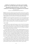
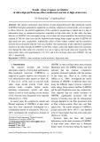
Expression (1) is the sum of the signal f(t) at all
times multiplied by a complex exponential
function. The result of the Fourier transform is
the Fourier coefficients F(ω). These Fourier
coefficients, when multiplied by a frequency
sine wave of frequency ω, become the sine
components that make up the original signal as
shown in Figure 1. Geometrically, the process
is as follows:
Diagnosis of spiral bevel gear damage using the Wavelet transform model
17
Figure 1. Signal analysis using the Fourier transform.
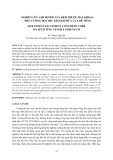
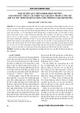
Similarly, the wavelet transform is defined as
the sum over the entire time interval of the
signal multiplied by the scaled and shifted
versions of the wavelet function ψ.
( , ) ( ) ( , )C scale position f t scale position dt
+
−
=
(2)
The result of the Continuous Wavelet transform
(CWT) is a multitude of wavelet coefficients
C(scale,position), which are functions of scale
and position, as shown in Figure 2. Multiplying
each coefficient by the wavelet at the
corresponding scale and shift reconstructs the
original signal.
Figure 2. Signal analysis using Wavelet transform.
3. The Relationship between vibration
frequency and damage in spiral bevel gears
Gear transmissions generate vibrations and
oscillations at characteristic frequencies
because of the precise meshing of gear teeth.
These frequencies are related to rotational
speed and the number of teeth, ensuring
efficient power transmission, reducing noise
and vibration, and increasing the durability and
lifetime of the system. Analysing these
frequencies provides crucial information about
the operational condition of the gear
transmission, enabling early detection of
damage and timely maintenance:
1 1 2 2
..
C
F Z f Z F==
(3)
Where: Z1 and Z2 are the number of teeth on the
drive and driven gears, respectively; f1 and f2
are the rotational frequencies of the driving and
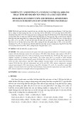
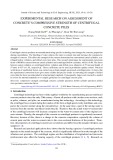
driven shafts. A normal gear transmission has
frequency bands on each side, equally spaced
by the rotational frequency f1 of the input shaft
and symmetrically around the meshing
frequency Fc, as shown in Figure 3.
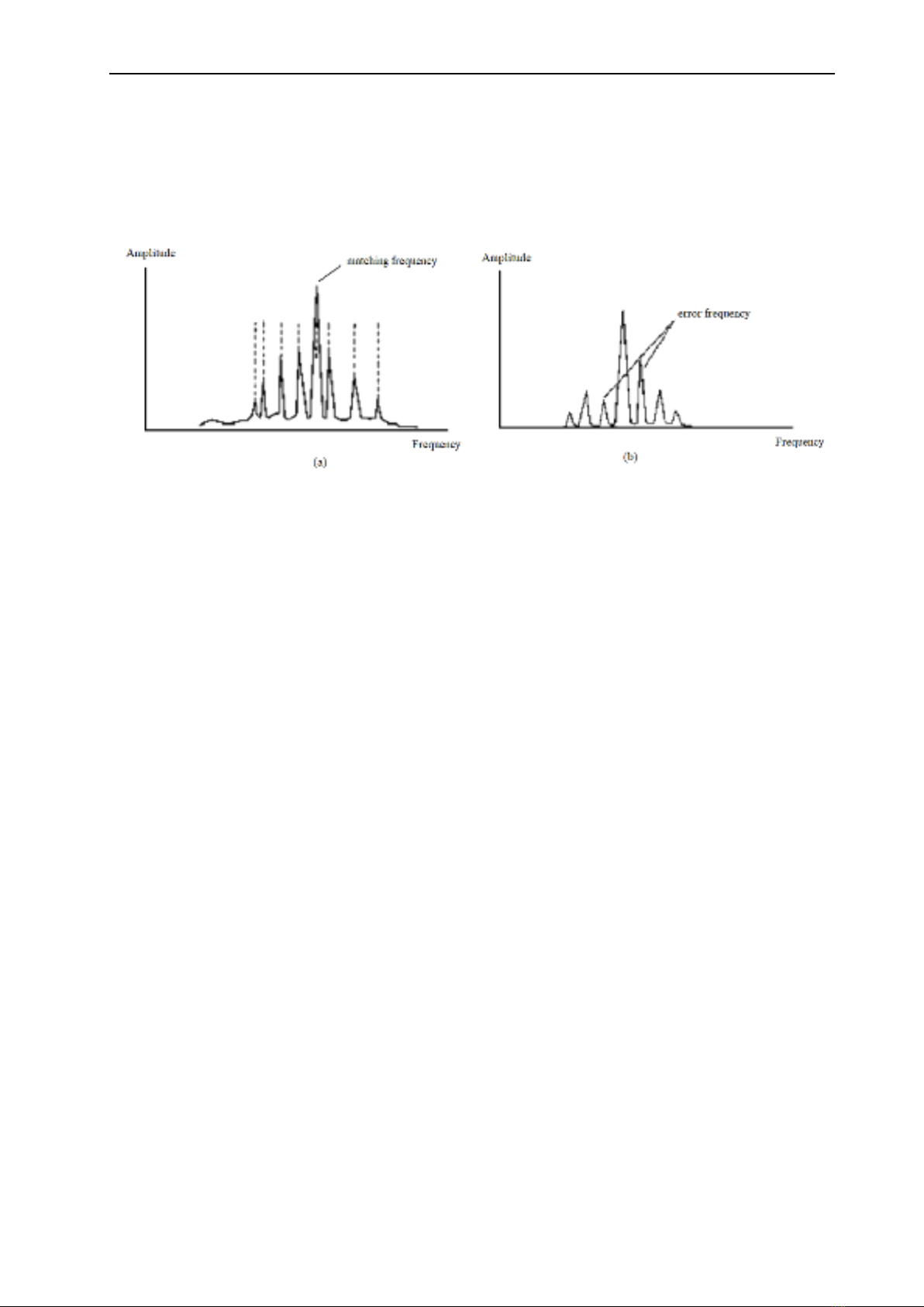
Figure 3. Frequency range and frequency spacing
of the gear transmission.
The vibration signal of a gearbox is very
complex, comprising oscillations of gears,
rolling bearings, rotating shafts, and other
Vo Tuan Kiet et al.
18
components. The structure of the vibration
signal frequency spectrum includes frequency
components from gear meshing, bearing
frequencies, and shaft rotational frequencies,
often in the form of harmonics. When a gear is
damaged, the vibration signal changes,
reflecting deformations or deviations in the
meshing process. Analysing these frequency
components helps determine the operational
condition of the gearbox and enables early
detection of damage for timely maintenance.
Figure 4. The vibration frequency shows gear damage.
(a) Axle distance is wrong; (b) Gear has cracks or broken teeth.
In the case of a broken or cracked gear, the
frequency spectrum of a gear transmission with
a broken tooth will have a higher amplitude on
the right side of the meshing frequency, causing
a characteristic asymmetry that indicates this
type of damage and aids in diagnosing the
problem as shown in Figure 4. On the contrary,
if there is a misalignment in the gear shaft
spacing, the vibration frequency spectrum will
change. When gear teeth wear out, the variation
in shaft spacing leads to changes in the spacing
and amplitude of the frequency spectrum.
When the shafts are too close together, the
spacing between the sidebands moves toward
the input shaft frequency, but the amplitude
decreases significantly. These variations are
key indicators for identifying issues related to
shaft spacing and gear tooth wear, helping to
achieve an effective diagnosis and maintenance
of the transmission system.
4. Results and discussion
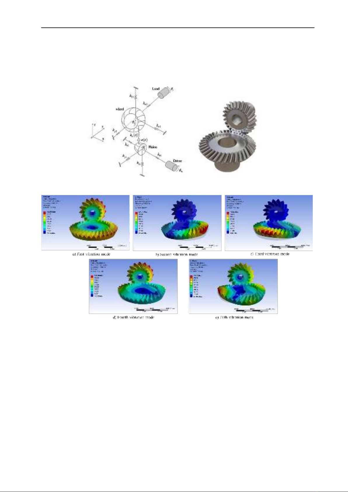
4.1. Vibration model of spiral bevel gears
The analysis of the vibration model using
simulation is a crucial tool for evaluating and
optimising the performance of gear
mechanisms during meshing. Figure 5
illustrates the results of the vibration model
analysis on a spiral bevel gear mechanism,
using wavelet analysis to examine parameters
such as deformation, stress, and displacement.
This allows us to assess the overall deformation
of the meshing position on the gear across
various frequencies. The vibration results of
Figure 8 demonstrate the overall deformation of
the gears under the influence of different model
frequencies, ranging from 9468.9 Hz to
29707.7 Hz. The deformation of the gears is
measured and displayed using different colours,
with maximum and minimum values identified
for each vibration mode. Model analysis shows
that the gear mechanism undergoes significant
deformation at specific frequencies during
operation, particularly in the upper part of the
driving gear.
The deformation tends to concentrate on the
upper part of the gear mechanism in most
modes, indicating that this area is more
susceptible to stress and vibration. At lower
frequencies (9468.9 to 12600 Hz), as in Figure
6, higher deformation is observed, suggesting
that the gear mechanism is more sensitive to
vibrations within this frequency range.
Therefore, these frequencies require special
Diagnosis of spiral bevel gear damage using the Wavelet transform model
19
attention during gear design and durability
testing. Areas experiencing the highest stress
and deformation are consistent in all vibration
modes, highlighting critical points that may
need reinforcement or design improvements to
enhance performance and durability.
Reinforcing high-stress areas and optimising
the design for low-frequency vibrations can
provide significant benefits, improving the
performance and durability of the gear system.
Figure 5. The dynamics of a spiral bevel gear model in mesh.
Figure 6. Gear vibration model through 5 modes.
The method studied in this paper offers
significant advantages in the vibration analysis
of spiral bevel gears during meshing. First, this
method allows for the accurate modelling of the
motion equations of the gear system, including
dynamic variables, structure, and boundary
conditions, resulting in a detailed and
comprehensive mathematical model. Dynamic
analysis through wavelet analysis helps identify
characteristics such as frequency and amplitude
of vibrations, enabling the recognition and
analysis of specific vibration modes and their
impact on system performance. In particular,
early detection of signs of damage such as
deformation, stress, and displacement in gears
facilitates timely maintenance and repairs,
minimizing the risk of severe damage and
extending the system's lifespan. This method
also enables the assessment of the effects of
different vibration frequencies, identifying
sensitive frequencies that cause high
deformation and stress, thus optimising the
design and durability testing of gears. With the
ability to simulate real-world scenarios and
optimise design, this method not only improves
performance and durability, but also reduces
![Cẩm Nang Xây Dựng: Quy Định Pháp Luật Cần Biết [Chuẩn Nhất]](https://cdn.tailieu.vn/images/document/thumbnail/2025/20251225/tangtuy08/135x160/80661766722918.jpg)