Cooling channel design for improving quality of injection plastic productPham Tuan NghiaTran Dai Nghia UniversityABSTRACTInjection molding is the most widely used technique for making the related plastic parts for consumer electronics goods with limited lifespans, like mobile phones, which are growing more and more popular. The molten plastic beads must be injected into a mold cavity, cooled, then part-formed and ejected. Filling, packing, cooling, and ejection are the four key steps in an injection molding process. The length of the molding cycle affects how economical the procedure is. The cooling step is the most crucial of the three since it controls how quickly are produced. Otherwise, cooling systems are important for the injection molding process in terms of productivity, quality, and mold-making costs. In this paper, three conformal cooling channel designs are proposed for obtaining uniform cooling over the molded parts. The research is conducted by using CAE software (MOLDEX 3D) to simulate the injection process and compare the results of three conformal cooling channel designs with molded part cooling by moldbase. All three designs show that warpage and cycle time improve significantly, helping to decrease cost and increase productivity. In which the combination of a conformal cooling channel outside and a baffle cooling channel significantly reduces the warpage.Keywords: Injection molding, plastic product productions, conformal cooling channel (CCC)Nowadays, plasc products appear in many segments of life such as electronics equipment, healthcare, construcon, transportaon, agri-culture, wide range of use include outstanding material characteriscs like high strength-to-weight rao, sffness and toughness, duclity and low lifeme cost. Among many ways to produce plasc products, the injecon molding process seems to be the most common method.The basic principle of injecon molding is to melt plasc pellets and inject them into a cavity in a mold. Aer cooling, the part is ejected from the machine. Therefore, the main stages of the injecon molding process are filling packaging, cooling and ejecon. Process economics depend on the me spent in the molding cycle. The cooling phase accounts for up to 80% of the total cycle me and directly influences the shape deviaons (due to shrinkage, bending, warping, etc.) of the final plasc part [1] , so it determines the rate at which the parts are produced. Therefore, the cooldown phase is the the most important step of three. Cooling systems, which typically consist of a succession of straight-drilled holes as shown in Figure 1 [2], are required in molds in order to cause the injected materials to cool down. Straight-drilled channels cannot provide ideal cooling because their layouts are constrained by the cavity form (to minimize interference between the cavity and channels) and drilling technique (only straight holes may be drilled), despite the fact that they are simple and inexpensive to make. As a result, straight-drilled circular channels are required by manufacturing limitaons even if they might not be the best choice for the mold cooling process.In recent years, the cooling efficiency has not been as high as desired when using straight-drilled cooling molds. On the other hand, sharp turns at the connecon of two adjacent straight-drilled channels (Figure 1), limit the coolant mobility, causing a rapid pressure drop that reduces the cooling capacity downstream and increases the uneven cooling [3].101Hong Bang Internaonal University Journal of ScienceISSN: 2615 - 9686Hong Bang Internaonal University Journal of Science - Vol.4 - June 2023: 101-108DOI: hps://doi.org/10.59294/HIUJS.VOL.4.2023.392Corresponding Author: Pham Tuan NghiaEmail: nghiapt91@gmail.com1. INTRODUCTION
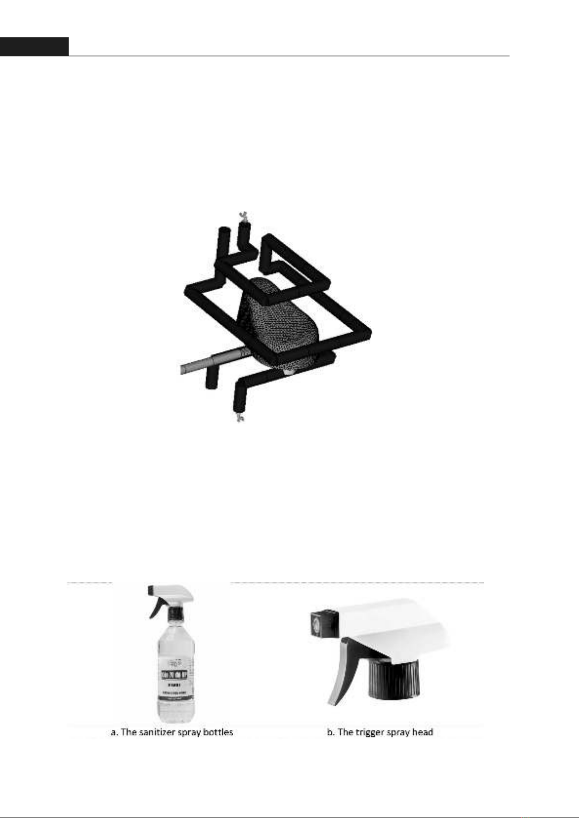
The parts created via thermoforming typically have a thin shell, intricately curved surfaces, and/or deep hollow structures [4]. Due to the deep hollow feature's propensity to cause localized heat accumulaon, differenal shrinkage and warpage are more severe and cooling rates are substanally lower in these circumstances [5]. This may necessitate costly mold correcon to guarantee that the part has the desired accurate dimensions [6]. Conformal cooling (CC) channels were introduced in the 1990s as a way to reduce warpage and accelerate cooling. The CC channel has a constant distance from the cavity surface and is designed as a curved channel [7]. This reduces the distance between the channel and the cavity surface and guarantees a consistent cooling rate along the channel. CC channels can therefore greatly improve the cooling performance of the mold by minimizing temperature differenals [8].In some cases, with proper cooling channel designs, CC channels can reduce the cooling me by as much as 80% [1] and the cycle me by 60 – 70% [9]. Thus, it is clear that a CC channel network's ideal design is essenal for producing products more rapidly, consistently, and effecvely. To achieve specificaons for cooling performance, mechanical strength, coolant fluidity, and other factors, several fundamental design criteria must be followed.The demand for using the trigger spray head is increasing today. It is easy observe that in the Covid-19 the sanizer spray boles (Figure 2a) are very common and useful in epidemic prevenon. So that is a challenge to the manufacturing system about parts producon of trigger spray heads (Figure 2b). Figure 1. Convenonal cooling channel (straight-drilled holes) in mold [2]Figure 2. The sanizer spray boles are used in Covid padamic prevenon102Hong Bang Internaonal University Journal of ScienceISSN: 2615 - 9686Hong Bang Internaonal University Journal of Science - Vol.4 - June 2023: 101-108
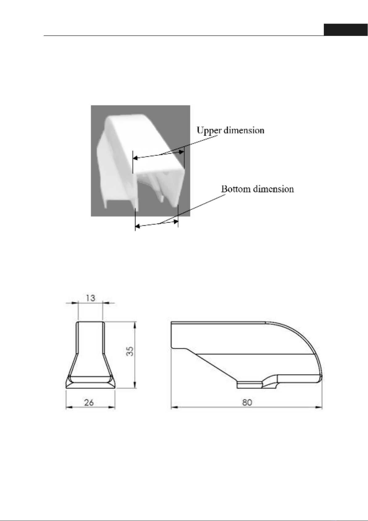
103Hong Bang Internaonal University Journal of ScienceISSN: 2615 - 9686Hong Bang Internaonal University Journal of Science - Vol.4 - June 2023: 101-108On the other hand, all of the trigger spray head parts are products of the plasc industry, and some defects appear in components of the trigger spray head such as the head cover. It can be seen in Figure 3 that the boom dimension is smaller than the upper one, possibly due to warping. In this paper, the cooling channel designs of the head cover and are invesgated in order to improve the quality of injecon products by reducing warping (deformaon) due to shrinkage and increasing producvity by reducing cooling me.2.2. Gate locaonThe injecon gate can only be posioned on the product's two sides due to its geometry; if it were to be placed on the top or boom, it would prevent the mold from being separated aer each injecon. Addionally, the gate needs to be on the other side of the product because one side has a small thickness (1 mm). Even so, the placement of the gate guarantees that the rao L/t stays within the acceptable range for PP materials. (Figure 5). 2. MOLDED PART ANALYSIS2.1. The modelThe real part has been redesigned using CAD soware and its primary dimensions are shown in Figure 4.Figure 3. The head cover image is taken from the real productFigure 4. The primary dimension of head cover
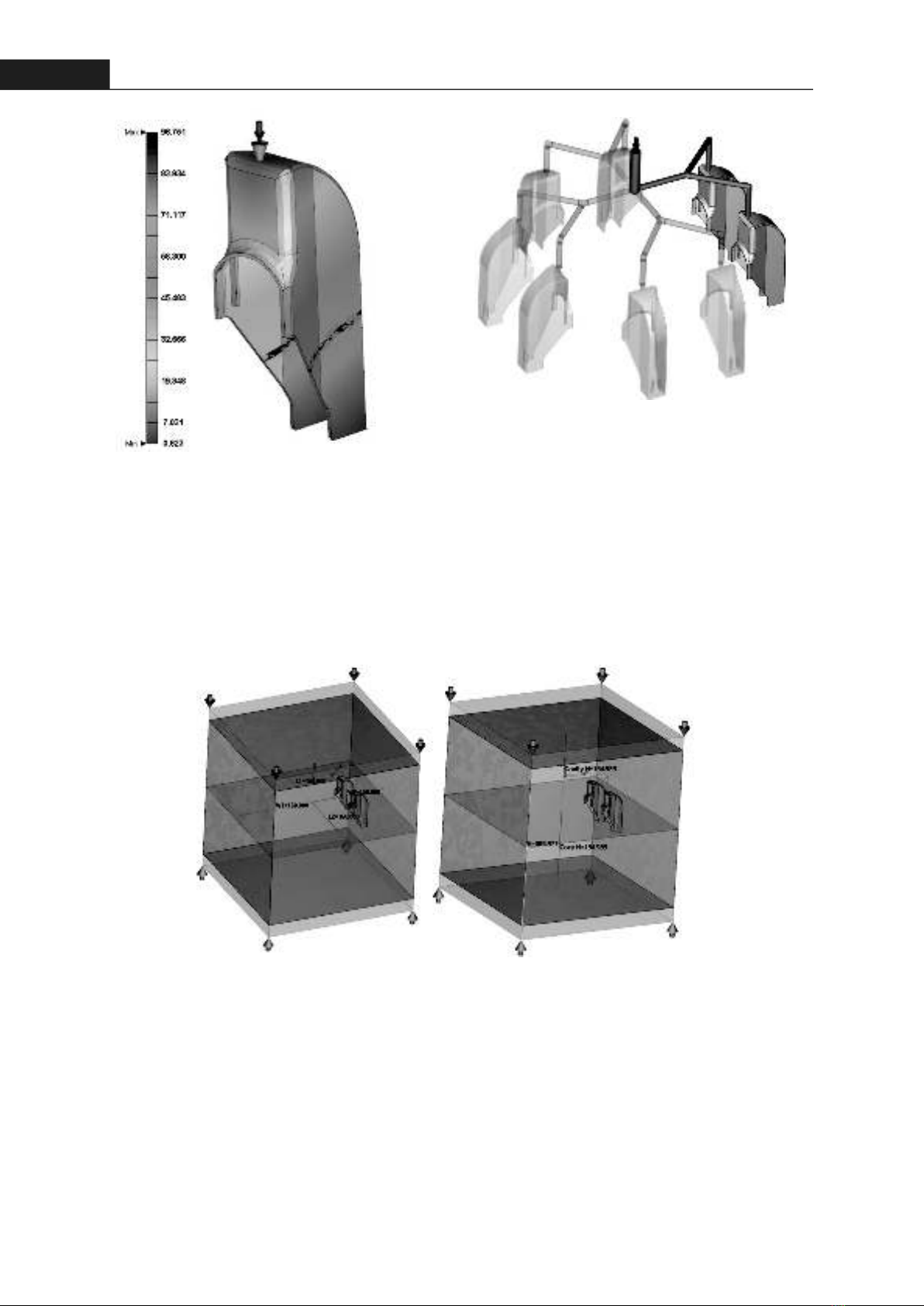
104Hong Bang Internaonal University Journal of ScienceISSN: 2615 - 9686Hong Bang Internaonal University Journal of Science - Vol.4 - June 2023: 101-108Figure 5. Gate locaon and L/t rao2.3. Runner system configuraonDue to the relavely small size of the details, the mul-component molding funcon should be used, specifically employing a hot runner system (Figure 6). In this project, a hot runner system is ulized, where the main runner has a diameter of 8mm and the sub-runner has a diameter of 4.5mm.Figure 6. Runner configuraon type symmetry 1/42.4. The trial simulaonIn the trial simulaon, the molded parts use a moldbase (Figure 7) without a cooling channel (parts are cooled by the moldbase) for the purpose of invesgang the main factors causing defects for the part, thereby correcng the parameters of the injecon process and serving as a basis for designing the proper cooling channel design. The moldbase dimension is 320x320x310mm (LxWxH).Aer the trial simulaon, the parts are completely filled in aer 1.286s and no weldlines appear, the molten core is completely frozen aer 4.575s at the end of the packing process. The cooling phase takes 3.701s for the parts to reach the ejecon temperature. The sinkmark displacement and the volumetric shrinkage are quite small, as shown in Figure 7. The total displacement is maximum at the end of the part as shown in Figure 8a and the maximum value is 0.868mm the differenal shrinkage effect on the displacement is signi-ficantly greater than the differenal tempe-rature (Figure 8b). Base on the result of trial simulaon, main reason cause the warpage that is the differenal shrinkage. However, the volumetric shrinkage is quite low and the molten core is completely frozen, so the packing pressure and the packing me are efficient for this stage.Figure 7. Moldbase without cooling channel
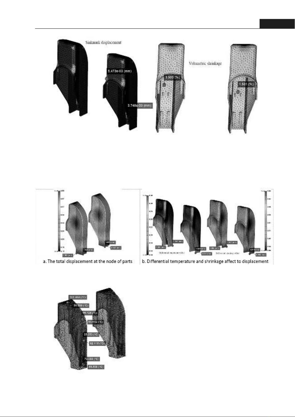
105Hong Bang Internaonal University Journal of ScienceISSN: 2615 - 9686Hong Bang Internaonal University Journal of Science - Vol.4 - June 2023: 101-108When checking the temperature distribuon at the EOP (end of packing), the differenal temperature between inside and outside of the part, the top and boom of the part, as shown in oFigure 9, is about 20C (to be considered). This differenal makes the shrinkage uneven. Therefore, the need for a cooling channel inside the part is verified.Figure 10. The temperature distribuon at EOP2.5. Cooling channel designFor cooling the part, the designed cooling channel has three configuraons:1. The baffle cooling channel (Internal cooling to reduce the differenal of temperature between the inside and outside of the part) (Figure 11a)2. The conformal cooling channel (CCC) inside is designed with the shape as can be seen in Figure 11b so that the CCC's path follows the internal geometry of the part.3.The combinaon between the baffle cooling channel and the conformal cooling channel outside (Figure 11c).Figure 8. The sink mark displacement and the volumetric shrinkageFigure 9. The total displacement at the node of parts

![Giáo trình Động vật hại nông nghiệp và nông sản (Nghề Bảo vệ thực vật Trung cấp) - Trường Trung cấp nghề GDTX Hồng Ngự [Mới nhất]](https://cdn.tailieu.vn/images/document/thumbnail/2024/20240417/khanhchi0912/135x160/4741713340904.jpg)

![Giáo trình sản xuất cây giống bằng hạt [chuẩn nhất]](https://cdn.tailieu.vn/images/document/thumbnail/2013/20131112/lengocln/135x160/1041384246790.jpg)