* Corresponding author.
E-mail addresses: bkleest@wku.ac.kr (B. K. Lee)
© 2018 by the authors; licensee Growing Science, Canada.
doi: 10.5267/j.esm.2017.11.001
Engineering Solid Mechanics (2018) 39-50
Contents lists available at GrowingScience
Engineering Solid Mechanics
homepage: www.GrowingScience.com/esm
Elastica and buckling loads of nonlinear elastic tapered cantilever columns
Joon Kyu Leea and Byoung Koo Leeb*
aDepartment of Civil Engineering, University of Seoul, Seoul, Korea
bDepartment of Civil and Environmental Engineering, Iksan, Jeollabuk-do, Korea
A R T I C L EI N F O A B S T R A C T
Article history:
Received 26 June, 2017
Accepted 1 November 2017
Available online
1 November 2017
This paper deals with the elastica and buckling loads of the nonlinear elastic tapered cantilever
columns subjected to an axial load at the free end. The column cross section is rectangular,
where the width and depth vary linearly with the column axis. The column material is nonlinear
elastic, which obeys the Ludwick’s constitutive law. The ordinary differential equations
governing the elastica of buckled column are derived and solved numerically for computing
the elastica and buckling loads. Parametric studies for the annealed copper, N.P. 8 aluminum
alloy and steel columns are conducted.
© 2018 by the authors; licensee Growing Science, Canada
Keywords:
Elastica
Buckling load
Tapered column
Ludwick type material
1. Introduction
Elastica problems dealt with the large deflection beam theory are one of the greatest interest themes
in the field of structural engineering. Since the first study of the elastica was published by Euler (1774),
in which large deformed shapes of a slender rod were studied, such elastica problems have been still
discussed to the present day. Much reference, particularly on the cantilever beams/columns, and their
citations include the mathematical models and the significant historical literature on this subject.
Concerning the large deformation beam theory, typical works related to this study should be classified
into two column materials: the linear and nonlinear elastic materials. Firstly, very much works related
to the elastica of the linear elastic materials had been published in the past few decades. For typical
examples, various effects on the elastica responses had been extensively investigated, such as solution
methods (Berkey & Freedman, 1978; Panayotounakos & Theocaris, 1988; Lee & Lee, 2017); loading
conditions (Berkey & Freedman, 1978; Nageswara & Rao, 1990; Lee & Oh, 2000; Borboni & Santis,
2014); variable cross sections (Nageswara & Rao, 1990; Lee & Oh, 2000; Lee & Lee, 2017); optimal
shapes (Berkey & Freedman, 1978; Lee & Lee, 2017); and secondary effects such as shear deformation
(Nageswara & Rao, 1990; Lee & Lee, 2017).

40
Secondly, works dealing with the elastica of the nonlinear elastic materials which obey the Ludwick
type constitutive law directly related to the present study are very limited. For elastica problems of the
nonlinear elastic beams, several works are shortly introduced: Lewis and Monasa (1981, 1982) solved
the large deflections of the prismatic beams subjected to the point load and tip couple, respectively;
Lee (2002) studied the large deformed prismatic beams with both the tip point load and uniform load;
Jung and Kang (2005) studied the large deflections of cantilever beams with the nonlinear elastic
materials; Eren (2008) solved the large deflections of the rectangular combined loaded beams by means
of different arc length assumptions; and Brojan et al. (2009) investigated the large deflections of
nonprismatic/tapered beams with the tip couple.
For elastica problems of the nonlinear elastic column, very limited number of works had been
published in the past few decades. Typical works are shortly reviewed: Kounadis and Mallis (1978)
presented the post-buckling response of a simply supported, axially compressed, uniform bar of
nonlinearly elastic material, in which the bar axis shortening was taken into account; Haslach (1985)
analyzed the post-buckling behavior of the column made of a material with cubic constitutive equation
to discover the post-buckling load deflection relationship; Lee (2001) investigated the post-buckling tip
responses of uniform column under a combined load consisting of a uniformly distributed axial load
and concentrated load at the free end; Jung and Kang (2005) studied the large deflections of cantilever
columns with the modified Ludwick nonlinear elastic materials; Brojan et al. (2007, 2009) presented
the buckling stability characteristics of nonlinear elastic column, depending upon the values of different
material parameters; and Saetiew and Chucheepsakul (2012) studied the post-buckling behavior of the
linearly tapered and simply supported column made of the nonlinear elastic materials.
This paper aims to investigate the elastica and buckling loads of the nonlinear elastic tapered
cantilever columns subjected to an axial compressive load. The column cross section is solid
rectangular, whose width and depth are linearly varied, respectively, along the column axis. The
nonlinear column material obeys the Ludwick type constitutive law. Analyses of the elastica are based
on the large deflection beam theory, which deals with the geometric nonlinear differential equations
that relate the deflection to the load. Following assumptions are inherent: the column material is
nonlinear elastic; the cross section is rectangular; the neutral axis for bending is incompressible; the
plane sections remain plane; the shear deformation is ignored; and the axial load direction is vertical.
This study begins with defining both the width and depth of the tapered rectangular column. It
derives differential equations which govern the elastica of the buckled column, and then solves these
equations numerically for calculating the elastica and buckling loads using the Runge-Kutta and
Regula-Falsi methods. The buckling loads and tip responses of the elastica obtained from this study are
compared to those in the open literature for the validation purpose. This study extensively discusses
numerical results of the elastica and buckling loads for the annealed copper column, and finally ends
with comparisons the buckling load elastica and extreme stresses for three different column materials
of the annealed copper, N.P. 8 aluminum alloy and steel. Nowhere in the open literature were found
solutions for the buckling analysis of cantilever columns considered both the nonlinear elastic
(Ludwick type material) and taper effects.
2. Mathematical modelling
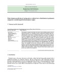
Shown in Fig. 1 is the geometry of the tapered cantilever column with the length, where the bottom
end is clamped and top end is free. The column cross section is solid rectangular, whose width and
depth vary linearly in and directions, respectively, with the axial length measured from the
clamped end. The width and depth at any are represented as and, respectively. Those of the
clamped end (0) are and, and those of the free end () are and, respectively.
In addition, note that axis is the bending axis.

J. K. Lee and B. K. Lee / Engineering Solid Mechanics 6 (2018)
41
For functionally expressing and with, following two nondimensional section ratios are
defined as
(1)
(2)
Considering and introduced above, and at any are expressed as a function of, or
1
1
1 (3)
1
1
1
(4)
where,
1 and
1.
Fig. 1. Geometry of tapered cantilever column Fig. 2. Pre- and post-buckled column with their variables,
and positive sign convention of stress resultants
Symbols and loadings for the cantilever column with length are defined in Fig. 2, which is
subjected to an axial load. The pre-buckled column, illustrated as a dashed line, is still straight, since
is less than the buckling load. However, once becomes to be greater than,
the column buckles and forms the elastica, an exact shape of the buckled axis, depicted as a solid curve.
The elastica is defined in the rectangular coordinates,. The buckled arc length at , is
measured from the clamped end as previously depicted in Fig. 1. For the pre-buckled column, the axis
coincides with the vertical -axis, whereas for the post-buckled column, the axis no longer aligns with
the -axis. After buckling the column, the material point marked by on the straight axis moves to the
material point marked by on the post-buckled axis. The arc length at the free end maintains the
length because of the assumption of incompressibility. The angle rotation of the elastica is depicted
as. The axial force, shear force, and bending moment on the elastica are depicted as, and,
respectively, where their respective positive sign conventions are presented in Fig. 2. At the free end,
the horizontal and vertical deflections, and angle rotation are illustrated as ∆ and∆, and,
respectively. From the stsatcs, stress resultants of , and at any on the elastica are expressed as
cos (5)
sin (6)
∆ (7)
If a cross section is defined and a stress-strain curve of the material is prescribed, an equation
connecting curvature and moment can be established. In this paper, the column is made of a
nonlinear material where the stress-strain curve is represented by the Ludwick relation (Lee, 2001,
2002), that is
||
⁄, (8)
f
c
s
l
x
z
yz
x
W
f
x
D
y
W
W
D
W
c
D
c
W
f
D
f
W
c
D
c
D
f
P < B PB
f
s=l
l
y
cs=0
(x, y)
(A, Q, M)
(W, D)
Δv
x
s
θ
f
A
A
Q
Q
M
M
θf
Δh

42
where and represent the stress and strain, and the constants and represent the mechanical
properties of the material, respectively. Note that the sign of in Eq. (8) follows that of.
The bending moment-curvature relationship for the rectangular cross section with and of the
Ludwick type nonlinear elastic material can be written as (Lee, 2002),
⁄
21
⁄
2/
⁄
⁄
21
⁄
2/
⁄
(9)
in which the term of
⁄ is selected rather than that of curvature
⁄ for the sake of
convenience in developing the elastica theories hereafter.
Substituting Eq. (7) into Eq. (9) together with Eqs. (3) and Eq. (4) and rearranging gives
⁄
⁄
⁄∆
⁄; 0
(10)
In subsequential process, two differential equations are obtained from the large deflection beam
theory:
cos (11)
sin (12)
Now consider the boundary conditions of the column. At the clamped end0, no deflections
occur, or
0 (13)
0 (14)
0 (15)
Since ∆ in the differential equation, eq. (10), is unknown, differential equations, eqs. (10)-(12), as
an initial value problem, cannot be solved. In order to determine the unknown∆, the boundary
condition at the free end is considered, as a boundary value problem. At the free end, the
horizontal deflection ∆ clearly equals the coordinate, or
∆0 (16)
To facilitate numerical studies and to obtain the most general results for this class of the problems,
the loadings, geometric parameters, and governing equations with their boundary conditions are cast in
the following nondimensional forms. Firstly, the axial load and buckling load parameters are defined
as
, (17)
, (18)
where,
12
⁄.
The stress resultants of, and are normalized as
(19)
(20)

J. K. Lee and B. K. Lee / Engineering Solid Mechanics 6 (2018)
43
(21)
The width and depth at the clamped end are normalized by the length as
(22)
(23)
The arc length and coordinates , are normalized by the length, or
(24)
(25)
(26)
The tip deflections of ∆ and ∆ at the free end are also normalized by the length, and the angle
parameter against the tip rotation is defined as
Δ
(27)
Δ
(28)
(29)
where it is particularly noted that the elastica has negative curvature when is larger than 0.5,
i.e.,0.5.
Combining the differential equations of Eqs. (10-12) and the nondimensional parameters of Eqs. (17-
27) yields
/
⁄
⁄
⁄; 01 (30)
cos (31)
sin (32)
Eqs. (30-32) derived above are the totally third order nondimensional differential equations which
govern the buckled shape of the nonlinear elastic tapered cantilever column.
The boundary conditions of the clamped end0, Eqs. (13-15), become
0 (33)
0 (34)
0 (35)
The boundary condition of the free end1, Eq. (16), becomes
=0 (36)
3. Numerical methods
Based on above analyses, two FORTRAN computer programs were written to calculate the elastica
and the buckling load. The input column parameters are: the material properties of and ; the length
; the column geometry of , , and ; and the axial load . From these parameters given in the
dimensional units are transformed into those nondimensional forms: , and, and. For
integrating differential equations, the Runge-Kutta method (Carnahan & Luther, 1969) was used and


![Bài tập tối ưu trong gia công cắt gọt [kèm lời giải chi tiết]](https://cdn.tailieu.vn/images/document/thumbnail/2025/20251129/dinhd8055/135x160/26351764558606.jpg)