
EURASIP Journal on Applied Signal Processing 2003:12, 1188–1197
c
2003 Hindawi Publishing Corporation
Algorithm of the Radar Imaging by Using the Wideband
Signals with the Distorted Signal Phases
Yulia V. Zhulina
Interstate Corporation “Vympel”, 125319 Moscow, Russia
Email: yulia julina@mtu-net.ru
Received 16 December 2002 and in revised form 30 June 2003
The problem of restoring an image by its Fourier transform is considered when the Fourier transform contains phase distortions.
The nature of these distortions and their values are arbitrary. The criterion for the quality of the phase distortion estimates is
suggested. It can be used to select the image which is mostly like the true one. The nature of the true image is also arbitrary.
The only condition for the true image is that it is real and positive for all the points of the restored area. The other condition
for the task is that the recovered image is calculated as the absolute value of the inverse Fourier transform. The algorithm for
the search of the compensating phases satisfying the criterion is not considered for the general case; however, the task of the
radar imaging based on the wideband signal and the time synthesis of the aperture is treated in detail. The physical basis for
the task is a wideband pulse radar signal reflected by a moving object. As a result, a two-dimensional aperture is synthesized
along the range, due to the super resolution, and along the velocity, according to the motion of the object. The radar signals
are received by a single receiver. The image is reconstructed on the basis of these signals by using the maximum likelihood
technique. The method uses the coherent processing of the signals. In practice, the coherence can be destroyed (due to some
atmospheric turbulence or equipment instability, due to some inaccuracy in defining the motion). We assume that the objects
to be observed are located at the far zone. For this task and on the basis of the suggested criterion, we develop an approximate
algorithm for searching the best compensating phases in the radar signal. The quality of the images is tested with the help of
simulation.
Keywords and phrases: Fourier transform, phase distortions, radar imaging.
1. INTRODUCTION
A lot of tasks in optics, tomography, radar, and astronomy
are connected with image recovery by using the Fourier spec-
tra. The synthesis of the procedures for performing image fil-
tering, enhancement, restoration, and segmentation presup-
poses similar tasks. These spectrum data include some am-
plitude and (or) phase distortions of various types very of-
ten. The problem of compensating these distortions with the
aim of achieving high quality of image restoration is actual,
and different techniques were suggested to solve this prob-
lem both in radar science [1,2,3,4,5,6,7,8,9,10,11]
andinoptics[12,13,14,15,16,17,18,19,20,21,22]. It
is important to notice that in the Fourier optics, one of the
most topical tasks is the problem of simultaneous restora-
tion of the optical response function and of the object image
in the presence of some phase distortions related to atmo-
spheric turbulences. In the latter case, the restoration task is
a problem of blind deconvolution, but not that of the Fourier
spectrum restoration. Nevertheless, in the tasks of coherent
optics, such as laser optics, the problem of the Fourier spec-
trum restoration may be quite topical.
As for the radar imaging, the works which are most
close to our subject consider the synthetic aperture autofocus
methods. One approach is to choose a range cell, containing
a bright scatterer [8]. For a complex target, that does not have
a bright scatterer, the estimation of the pulse-to-pulse phase
difference of the reference point can be calculated by taking
the phase differences for each range cell and averaging them
with the weights proportional to the amplitudes of the sig-
nal in each of the range cells [2]. The alternative approach
suggests selecting only the range cells with strong scatter-
ers [3,4,9]. Another method, based on the image contrast,
has also been proposed for synthetic aperture autofocusing
[5,6]. In [1], the estimation of the complex phase vector was
formed by the exponential function of the phase rather than
the phase itself. In [7], the eigendecomposition of the signal
vector covariance matrix is used for correcting some aperture
phase errors.
During the recent 5–7 years, a powerful theory of
constructing mathematical objects (signals, functions, and
images) in a vector space, satisfying some multiple con-
straints, was developed. It is named “vector space projection
method” [23]. All the constraint spaces are convex and have

The Task of the Radar Imaging in Distortion 1189
a nonempty space of intersection. The basic idea of the so-
lution is as follows: an initial vector (i.e., an initial object) is
being projected to each of the sets of constraints step by step.
The unitary projecting to the full set of restrictions completes
the first iteration. The vector, which is obtained after the it-
eration, is considered to be the initial one for the next itera-
tion. The iterative process converges to the vector, satisfying
all the constraints simultaneously. This theory was success-
fully applied to the filter design tasks with the classical con-
straints: passband fluctuations, stopband attenuation, tran-
sition band behavior, and filter length (length of the impulse
response) [24,25]. In [26], the task of synthesis, a desirable
form of the far-field radiation pattern, is resolved. A task of a
self-healing in the arrays antennas is also considered.
The presented paper considers the case when there are
no amplitude distortions, but the phase distortions are pre-
sented in the Fourier transform. The nature of these dis-
tortions and their values are arbitrary. The criterion for the
quality of estimating the phase distortions is suggested and
it can be used to select the image mostly close to the true
one. The nature of the true image is also arbitrary. The con-
dition for the task is that the recovered image is calculated
as the absolute value of the inverse Fourier transform. The
algorithm for the search of the compensating phases satis-
fying the criterion is considered for the task of the radar
imaging by using the wideband signal and the time synthe-
sis of the aperture. For this task on the basis of the sug-
gested criterion, we will develop an approximate algorithm
for finding the best compensating phases in the radar signal.
The quality of the images is tested with the help of simula-
tion.
2. CRITERION FOR FINDING THE BEST IMAGE
OBTAINED AS A RESULT OF THE INVERSE
FOURIER TRANSFORM
We assume that the object to be reconstructed is placed in
the far Fraunhofer zone, so that the received field is a plane
space wave and the image ˆ
E(
s) is being constructed as the
inverse two-dimensional Fourier transform of the received
field ˆ
F(
R),
ˆ
E(
s)=1
(2π)2Ω
R
ˆ
F
Rexp −jk0
R
sd2
R. (1)
Here, k0=2π/Λρ,whereΛis the wavelength of the signal,
ρis the range, Ω
Ris an area of the receiving aperture,
sis a
coordinate vector in the object space, and
Ris a vector in the
Fourier space.
Suppose that the received field ˆ
F(
R) is distorted and is
connected with the true field F(
R) by the relationship
ˆ
F
R=exp jθ
RF
R.(2)
Here, θ(
R) is the function of the phase distortions. In this
case, the inverse Fourier transform (1) produces a distorted
image.
We can take any arbitrary estimation of the phase distor-
tions ˆ
θ(
R) and include this estimate as a compensating mul-
tiplier in the expression (1). As a result, we get the next ex-
pression for ˆ
E(
s) instead of (1):
ˆ
E(
s)=1
(2π)2Ω
R
ˆ
F
Rexp −jk0
R
sexp −jˆ
θ
Rd2
R.
(3)
The function ˆ
θ(
R) is unknown and must be found.
Further, we will designate the true image E(
s)andwill
limit the considerations to the images E(
s), for which
E(
s)=A(
s)expjϕ0,ϕ
0=const.(4)
According to (3), we can determine the estimate of the mod-
ulus ˆ
A(
s):
ˆ
A(
s)=
ˆ
E(
s)
=1
(2π)2
Ω
R
ˆ
F
Rexp −jk0
R
sexp −jˆ
θ
Rd2
R
.
(5)
Supposethatwecandoacompleteexhaustivesearchamong
the possible estimates of phase distortions ˆ
θ(
R)andwehave
no prior knowledge about the true function
A(
s)=
E(
s)
,(6)
so, for every new function ˆ
θ(
R), we get a new function ˆ
A(
s)
according to (5). Which of these functions ˆ
A(
s) in the pro-
cess of the search should be chosen as the best one?
In Appendix A, we show that in this case the best func-
tion ˆ
Abest(
s) among all possible ˆ
A(
s) satisfies the condition
Ω
s
ˆ
Abest(
s)d2
s≤Ω
s
ˆ
A(
s)d2
s, (7)
where Ω
sis the area, a priori occupied by the object.
So, the best estimation of the image must provide the
minimum to the integral over the area of restoration Ω
scom-
pared to all other estimates.
The first impression that the trivial result ˆ
Abest(
s)≡0is
the solution to the task is a mistake, since, according to (2)
and (5), the spectrum of ˆ
Ebest(
s)isequalto
ˆ
Fbest
R=exp jθ
R−ˆ
θbest
RF
R,(8)
and Parseval’s theorem gives
Ω
s
ˆ
A2
best(
s)d2
s=Ω
s
ˆ
Ebest(
s)
2d2
s
=1
(2π)2ΩR
F
R
2d2
R
=Ω
s
A2(
s)d2
s.
(9)

1190 EURASIP Journal on Applied Signal Processing
So, the full energy of the image remains constant in the pro-
cess of exhaustive search of phases ˆ
θ(
R).
3. THE TASK OF THE RADAR IMAGING WITH THE
DISTORTED SIGNAL PHASES
We consider a single radar transmitter, which radiates
the pulse signals un(t)(n=1,...,N) at the moments
t1,t
2,...,t
Nin the direction of the object under observation,
where Nis the number of emitted pulses and un(t) is the
shape of a complex pulse signal, emitted by the transmitter.
For example, the shape un(t)canbewrittenas
un(t)=ut−tn
=exp −α·t−tn2
+jωt−tn+∆ω·t−tn2.
(10)
Formula (10) corresponds to a Gaussian pulse with the car-
rier frequency ωand the linear frequency modulation.
The shape (10) is not necessary; the basic condition is
that the pulse un(t) should have a wideband of frequency
modulation.
Let
Robj(tn) be the position of the center of object’s masses
at time tnand
R0is the location of the radar receiver in the
coordinate frame with the origin in the center of the Earth.
For each moment tn,wehave
enwhich is the normalized
vector of viewing the object from the receiver:
en=A−1
objtn
Robjtn−
R0
Robjtn−
R0
,(11)
where Aobj(tn) is the matrix of object’s rotation around its
center of masses and A−1
obj(tn) is the inverse matrix.
We will not consider the problems of estimating the
rotation parameters and tracking objects here. We assume
that they have already been solved accurately enough in
[1,2,3,4,5,6,27]. We assume, as well, that the orbital mo-
tion of the object produces the synthesis of the aperture in
time. Thus, we assume that Aobj(tn) is the unit matrix.
The complex video signal Zn(λ)(n=1,...,N) with the
pulse number nat the output of the matched filter of the
radar receiver can be presented as, (in the far zone) [2,28,
29,30],
Zn(λ)=SLIGHT
E∗(
s)expjω2
eT
n·
s
c
·C0λ−2
eT
n·
s
cd2
sexp −jθn+mn(λ)
=¯
Zn(λ)+mn(λ).
(12)
Here, SLIGHT is the area of the object surface irradiated by
transmitter, C0(λ) is the autocorrelation function of the radar
pulse (the expression for it is given below),
sis the coordinate
vector of some element of object’s surface, d2
sis the element
of the surface in the coordinate frame connected with the ob-
ject center of masses, E(
s) is the complex-reflected signal of
the scatterer located on the surface of the rough object in the
point
s,λis a range (in time representation) with respect to
the center mass (after the compensation of the motion of the
mass center), mn(λ) is the additive complex Gaussian noise
at the output of the filter as in the function of time λwith
power σ2
noise and zero average and
eT
nis the transposed vector
of observation. In (12), θnis the phase distortion, generated
by the atmosphere on the way receiver-object and back.
Besides, the phase distortion may be caused by the phase
instability in the receiver. Some additional source of phase
distortions is the uncertainty of the motion of the object
mass center evaluation. The motion of the center of masses
gives shifts both to the position of each signal and to its
phase. If the phase shift, caused by this motion, is not accu-
rately enough compensated [1], this will lead to some phase
distortions of signals.
Further in (12), cis the velocity of light, ωis the carrier
frequency of the radar signal, and Nis the number of pulses
used in processing. Each signal ¯
Zn(λ) is the middle value of
video signal.
The autocorrelation function C0(λ)in(
12)canbeex-
pressed through the form of pulse u(t) as follows:
C0(λ)=∞
−∞
u∗(t)u(t−λ)dt, (13)
E(
s)in(
12) is unknown.
We will designate the modulus of the function
A(
s)=
E(
s)
(14)
as the unknown radar image of the object. It should be con-
structed by using the signals Zn(λ)(n=1,...,N).
The form of the receiver diagram is not included in (12),
because we assume that it is wider than the dimensions of
the object, and the tracking of the object is accurately enough
performed.
This task is a classical one in the radar tracking theory
and practice [10,11,31,32,33,34]. The most significant re-
sults of the radar imaging practice by using wideband signals
are presented in [32,35,36,37,38]. Here, we are developing
the approach to the restoration of the coherence in the radar
signals investigated earlier in [10,11].
4. MAXIMUM LIKELIHOOD ALGORITHM
Assuming that the noise mn(λ) is statistically independent of
different numbers n, we can write the logarithm of the likeli-
hood function for all the signals Zn(λ)(n=1,...,N):
LnP =− 1
σ2
noise
N
n=1λmax
λmin
Zn(λ)−¯
Zn(λ)
2dλ. (15)
Here, λmin is the minimum value of λamong the arguments

The Task of the Radar Imaging in Distortion 1191
of all the signals Zn(λ)(n=1,...,N), and λmax is the maxi-
mum value of λamong the arguments of all the signals Zn(λ)
(n=1,...,N).
The maximum likelihood estimate of E(
s)canbeob-
tained from the equations
δLnP
δRe E(
s)=0,δLnP
δIm E(
s)=0.(16)
These equations are the functional derivatives of the func-
tional LnP with respect to the functions Re E(
s)andImE(
s).
Appendix B proves that the solution of (16) gives the es-
timation of ˆ
E(
s) (to a constant factor):
ˆ
E(
s)=1
N
N
n=1
Z∗
nτn(
s)exp −jˆ
θn−ωτn(
s).(17)
Here, ˆ
θnis the estimation of the phase distortions while
τn(
s)=2
eT
n·
s
c,(n=1,...,N) (18)
is the time delay of the number nsignal from the surface
point of the object corresponding to
s.
To determine the coordinate frame of the image ˆ
E(
s), we
will introduce the axes of the coordinate frame
s.TheY-axis
is directed as the average line of sight (and upwards in all the
pictures). In other words, the direction of the Y-axis coin-
cides with the direction
eN/2.So,
e
s,Y =
eN/2.(19)
The X-axis is directed as the projection of the average (over
all the pulses) object velocity vector to the plane, orthogonal
to the vector
eN/2:
e
s,X =
vN/2−
eN/2
eN/2·
vN/2
vN/2−
eN/2
eN/2·
vN/2
.(20)
Here,
vN/2is the vector of the object velocity in the coordi-
nate frame, connected with the center of the earth, in which
the vector
eN/2is determined. The Z-axis is orthogonal to the
axes Xand Y.Thevector
e
s,Z completes the vectors
e
s,X and
e
s,Y to the right-hand coordinate frame.
It should be noted that in the direction
e
s,Z , the resolution
of the image recovery system is zero. Therefore, the three-
dimensional image ˆ
E(
s) is ,in fact, a two-dimensional image.
We will assume everywhere that
ˆ
E(
s)=ˆ
E
sX,
sY,0.(21)
If (17) is calculated, the image estimation ˆ
A(
s) is obtained
by using the formula
ˆ
A(
s)=
ˆ
E(
s)
(22)
and, according to (21),
ˆ
A(
s)=
ˆ
E
sX,
sY,0
.(23)
Algorithm (17) can work well enough only in case of the
concurrence of the estimations ˆ
θnwith their true values θn
(n=1,...,N) or if the estimations ˆ
θndiffer from their true
values by some constant value or linear addition along n
(n=1,...,N). In all other cases, the image (17)willbede-
stroyed. Further we suggest an algorithm for the evaluation
of the phase distortions ˆ
θn.
5. EVALUATION OF PHASE DISTORTIONS
We used the criterion (7) in the algorithm for the evalu-
ation of the phase distortions. The approach developed in
Appendix A is valid only for the true functions E(
s)for
which the expression (A.2) is in place. This means that the
functions E(
s) have a constant complex phase multiplier over
the whole scattering surface. Of course, (A.2)isnotcorrect
in a general case. However, for the objects of homogeneous
material, (A.2)canbeclosetoreality.In[1], the presented
examples also use the approximation (A.2). We should note
that the approximation (A.2) looks too strong, since nor-
mally the phase shift ϕ(
s) of each scatterer in the far zone
is understood as its range phase shift. In the expression (12),
the phase shift of the scatterer caused by its range is not in-
cluded into E(
s), but it is incorporated into the phase multi-
plier 2
eT
n·
s/c,where
sis a three-dimensional vector on the
surface of the object. In other words, the phase shift of each
scatterer due to its range is not a parameter to be estimated,
but it is the parameter of the algorithm (17). The expression
(17) is constructed by using all the possible vectors
s.Thus,
we will use the criterion (7).
The complete exhaustive search across all the values of
the phase distortions is impossible. Therefore, we have cho-
sen an approximately optimal algorithm described below
(formulas (24)and(25)). We mentioned above that the sig-
nals’ ranges λ(represented in time units (12)) lie within the
interval (λmin,λ
max). We divide this interval into the range
cells, each of a size equal to the range resolution. In terms of
the time units, the resolution del λis equal to del λ≈1.0/∆ω,
where ∆ωis the signal frequency deviation. The number Mλ
of these range (time) cells is Mλ=(λmax−λmin)/del λ.Wewill
designate the number of each range cell as m(1 ≤m≤Mλ).
The algorithm for the search of the unknown estimations ˆ
θn
(n=1,...,N) comprises the following operations.
At the first stage, all the phases ˆ
θn(n=1,...,N)are
taken as those of the signals Zn(λ)(n=1,...,N) in the first
rangecellwithm=1. By using the estimations ˆ
θn,wewill
construct the image by formulas (17)and(22) (in the whole
frame) and calculate the functional (7)
I1=Ω
s
ˆ
A(
s)d2
s. (24)
Then we will repeat the operations for the cell m=2. If the
value of the criterion I2<I
1, the estimations ˆ
θn, obtained at
the second step, look more preferable than the results of the
first step. All these operations are repeated Mλtimes. Finally,
the phases of Zn(λopt)(n=1,...,N) at the range λopt in the
1192 EURASIP Journal on Applied Signal Processing
cell with number mopt, satisfying the criterion
Iopt =min Im,1≤m≤Mλ,(25)
are taken as the final estimations ˆ
θn(n=1,...,N)andare
substituted in the final image estimations ˆ
E(
s)(see(
17)).
The estimations of the phase distortions obtained by this
process are approximate. However, the search is performed
in a 1-dimensional space and can be very fast. The results of
the reconstruction are shown in Section 6.
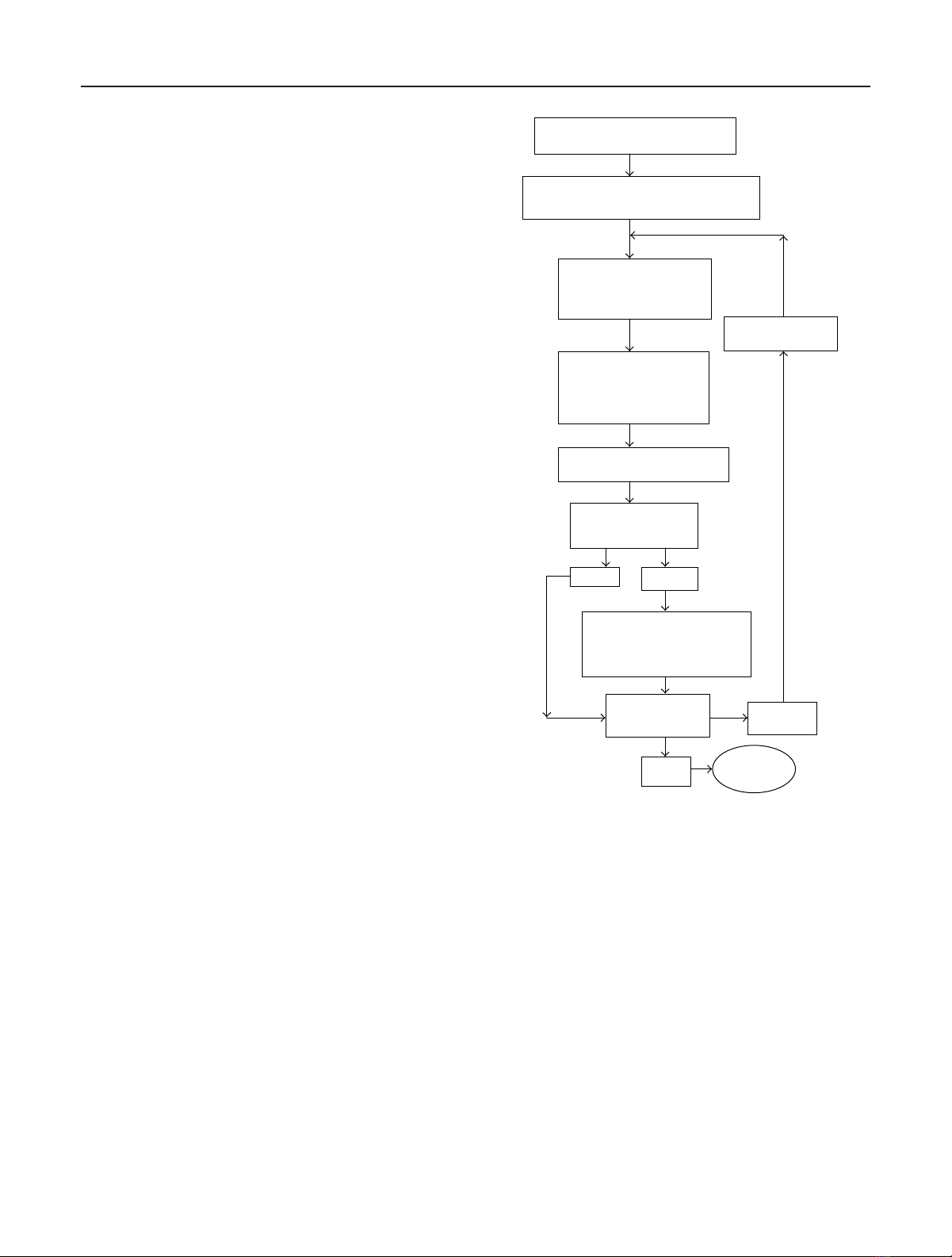
Figure 1 shows the diagram of the algorithm (24)and
(25) for finding the best compensating phases.
6. RESULTS OF DIGITAL SIMULATION
Figures 2,3,4,5,6,7,8,9,10,and11 present the results
of the digital simulation of the radar images. The three-
dimensional object is a Buratino doll with a dog on a chain.
The object consists of spheres, cylinders, and prisms and it
was simulated by using “OpenGL” package of 3D graphics
[39].
Figure 2 shows the true object in the image plane inside
the frame of 256 ×256 pixels. The vertical axis is the range
(the radiation is directed from the bottom to the top) and
the horizontal axis is the component of the object velocity,
orthogonal to the middle vector of viewing. The parameters
of the signals were taken as the typical ones for the American
station LRIR (Long Range Imaging Radar), well known as
Haystack [38], where the wavelength is 3.0 cm and the signal
band is 1.0 GHz for each radiated pulse.
Figure 3 presents the radar image of the object. The range
resolution is 0.3 m.
Figure 4 presents the similar image for the bandwidth
of 300 MHz for each pulse. The range resolution equals to
1.0 m.
The following parameters are the same for all figures: the
number of pixels is 256 ×256; the coherent processing of 256
pulses has been fulfilled. The scale division of the frame is
0.3 m. A circular Keplerian orbit with the range of 450 km to
the center of the masses of the object has been modeled. The
radiation rate was 0.005 seconds.
Figures 3and 4present the images reconstructed in the
absence of any additive noise in the signals.
Figure 5 presents the image with the maximum distur-
bance of coherence in the signals. These signals are obtained
by adding a random value to the phase of each received sig-
nal, and this random value is uniformly distributed within
(−π, π). In Figure 5 the image is also reconstructed in the
absence of any additive noise. The bandwidth is 1000 MHz.
The image, in fact, disappeared, and the only remaining pos-
sibility is to make estimations of its sizes along the range
axis.
Figure 6 presents the image for the case when the phase
distortions compensation algorithm is applied. We can eas-
ily see that the object is restored with certain loss of the res-
olution. Also the image may have some shift along the ve-
locity coordinate, because the algorithm reconstructs the un-
Z(1)
1···Z(M)
1···Z(1)
N
···Z(M)
N
m=1; Iont =1020
ˆ
θn=arg Z(m)
n
(n=1,...,N)
m=m+1
ˆ
E(s)withˆ
θn
Equation (17)
Im=ˆ
E(s)d2s
Im<I
opt?
No Yes
Iopt =Im
mopt =m
ˆ
Eopt(s)=ˆ
E(s)
m<M?Yes
No End
Figure 1: Diagram of the algorithm for finding the best compen-
sating phases.
known phases θn(n=1,...,N) with some possible constant
or linear addition along n. This leads to the restoration of the
image with the shift of the angle position in the frame.
In Figure 7, the image is reconstructed when the sig-
nal/additive noise ratio is equal to 2.0 in each element of
the range resolution. The bandwidth is 1000 MHz. The phase
distortions have the same statistical characteristics as those in
Figure 5. We can see that the image is worse than in Figure 5.
Because of the significant additive noise, the image has dis-
appeared even along the range coordinate.
Figure 8 presents the image after applying the compen-
sating algorithm. For comparison, Figure 9 represents the
image with the same parameters as in Figure 7 but with-
out any phase distortions. Figures 8and 9make it clear that
it is useful to apply the algorithm compensating the phase
![Mẫu Báo cáo tiến độ thực hiện đề tài [chuẩn nhất]](https://cdn.tailieu.vn/images/document/thumbnail/2025/20250318/tuongmotranh/135x160/1241742262566.jpg)