
* Corresponding author. Tel.: +98 21-61 118 572, Fax: +98 21-88 617 087
E-mail addresses:a_torabi@ut.ac.ir (A.R. Torabi)
© 2013 Growing Science Ltd. All rights reserved.
doi: 10.5267/j.esm.2013.08.005
Engineering Solid Mechanics 1 (2013) 99-118
Contents lists available at GrowingScience
Engineering Solid Mechanics
homepage: www.GrowingScience.com/esm
Failure curves for predicting brittle fracture in V-notched structural components loaded under
mixed tension/shear: An advanced engineering design package
A.R. Torabi*
Fracture Research Laboratory, Faculty of New Science and Technologies, University of Tehran, P.O. Box 13741-4395, Tehran, Iran
A R T I C L E I N F O A B S T R A C T
Article history:
Received March 20, 2013
Received in Revised form
August, 21, 2013
Accepted 21 August 2013
Available online
21 August 2013
Numerous failure curves are presented in this manuscript to predict the onset of sudden fracture
in V-notched brittle materials under combined tension-shear loading conditions. The curves
were developed in a computational manner in terms of the notch stress intensity factors and
based on the suitable failure concept of the maximum tangential stress (MTS) utilized
frequently in the past by the author and his co-researchers for predicting mixed mode brittle
fracture in extensive notched specimens. Three extensively used notch angles and various notch
tip radii were considered in the computations. A wide range of brittle materials were also taken
into account by defining and using the material critical distance. Through predicting load-
bearing capacity and notch bifurcation angle utilizing only the two basic material properties
namely the ultimate tensile strength and the plane-strain fracture toughness, engineers can
design more rapidly and conveniently the V-notched brittle components with the aim to
withstand reliably against sudden fracture.
}}
© 2013 Growin
g
Science Ltd. All ri
g
hts reserved.
Keywords:
Failure curve
Brittle fracture
V-notch
Load-bearing capacity
Design package
Mixed mode loading
1. Introduction
Design plays a vital role in safe and reliable operation of engineering components and structures.
Despite general objectives exist in all kinds of mechanical design; the main goal is certainly to
prevent failure in components with an appropriate factor of safety. For this purpose, several failure
criteria has been proposed and utilized regarding different material and structural failures such as
yielding, tearing, brittle fracture, fatigue fracture, creep rupture, buckling etc.
An important branch of mechanical engineering, namely the fracture mechanics, is focused on the
design and analysis of the elements containing stress concentrators like cracks, flaws, scratches and
notches. Such elements can fail in different manners depending on the material properties and the
type of the loads applied. Since fracture occurs suddenly in brittle and quasi-brittle components and

100
structures, the main attention in fracture mechanics is paid to the brittle fracture as a catastrophic
failure.
Unlike cracks and flaws which in the most cases are unfavorable to appear in engineering elements,
notches, especially V-shaped ones, are employed because of some particular design requirements. A
V-notch concentrates stresses around its tip and hence can become prone to initiate crack(s). Such
cracks can propagate in the notched component and finally lead to fracture. From the fracture
mechanics point of view, the mechanisms of crack initiation and propagation from a notch tip are
fundamentally different for ductile and brittle materials. For brittle materials, the initiation of crack
from the notch tip consumes a great portion of the total fracture energy and the crack propagation is
very less contributed in energy consumption. This is because the crack growth is such a rapid and
unstable phenomenon that the final fracture occurs suddenly. Conversely, for ductile materials exhibit
large plastic deformations around notches, both crack initiation and propagation phases consume
considerable amount of energy during ductile rupture.
Various concepts of failure have been suggested in the open literature for predicting brittle fracture in
engineering components and structures containing sharp and rounded-tip V-notches. Lazzarin and
Zambardi (2002) made use of the equivalent strain energy density approach to predict failure in sharp
V-shaped notches under localized and generalized plasticity. The strain energy density concept has
also been utilized by the same and the other investigators to predict brittle fracture in V-notched
components under in-plane loading conditions (see for example Lazzarin and Zambardi, 2001; Berto
and Lazzarin, 2009a; Gomez et al., 2009; Ayatollahi et al., 2011a; Berto and Lazzarin, 2009b;
Lazzarin et al., 2009; Berto et al., 2012; Lazzarin et al., 2013). The other failure concept utilized by
Berto et al. (2008, 2009) for sharp V-shaped notches is the fictitious notch tip radius. Moreover,
several fracture criteria have been developed in the past based on determining a critical value for the
notch stress intensity factor, so-called the notch fracture toughness. In this context, one can refer to
Seweryn (1994), Gomez and Elices (2003a,b), Leguillon and Yosibash (2003), Gomez and Elices
(2004) and Ayatollahi and Torabi (2010a) for pure mode I and Ayatollahi and Torabi (2010b,
2011a,b), Ayatollahi et al. (2011b), Yosibash et al. (2006), Priel et al. (2007) and Torabi (2013) for
mixed mode I/II and pure mode II loading conditions.
One of the most important concepts of failure in the context of brittle fracture is the maximum
tangential stress (MTS) concept, proposed originally by Erdogan and Sih (1963) for investigating
mixed mode brittle fracture in cracked bodies. The MTS concept has been frequently employed by
Ayatollahi and Torabi to predict mixed mode brittle fracture in the V-notched Brazilian disc (V-BD)
specimens made of PMMA (Ayatollahi & Torabi, 2010b; Ayatollahi et al., 2011b), polycrystalline
graphite (Ayatollahi & Torabi, 2011a) and soda-lime glass (Ayatollahi & Torabi, 2011b). The main
conclusion obtained from the investigations presented in the four references above was that the MTS
model has been a satisfactory failure criterion with a very good accuracy in the context of mixed
mode brittle fracture of V-notches.
In this manuscript, extensive failure curves are presented based on the MTS model with the aim to
estimate the onset of mixed mode brittle fracture in V-notched components in the entire domain from
pure mode I to pure mode II. The curves were developed in a computational manner in terms of the
notch stress intensity factors (NSIFs) by using the linear elastic stress distribution around the notch
tip. By using such curves, as an advanced engineering design package, one can predict rapidly and
more conveniently the mixed mode fracture in V-notched elements made of brittle materials for
various notch angles and different notch tip radii.
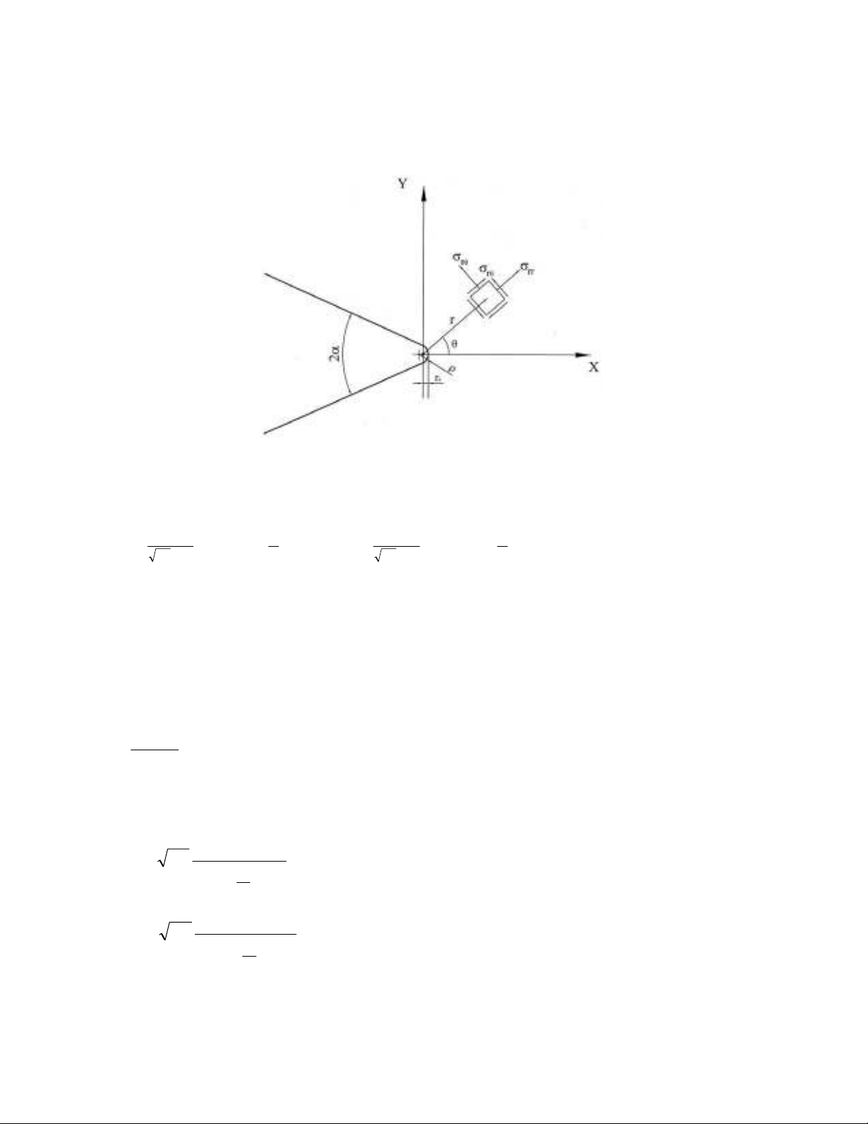
2. Elastic stress distribution around a V-notch tip
Filippi et al. (2002) developed an expression for mixed mode I/II stress distribution around a V-notch
shown in Fig. 1. The stress distribution is an approximate formula because it satisfies the boundary
conditions only in a finite number of points on the notch edge and not on the entire edge. They
A.R. Torabi / Engineering Solid Mechanics 1 (2013)
101
obtained the stress distribution using a conformal mapping in an auxiliary system of curvilinear
coordinates "U and V" that are related to the Cartesian coordinates "X and Y" as (X+iY) = (U+iV)q.
The power "q" is a real positive coefficient ranging from 1 to 2.
Fig. 1. Round-tip V-notch and its polar coordinate system
The mixed mode I/II stresses can be written as
)(
0
)(
1
,
)(
0
)(
1
,
)(
)(
)(
)(
)(
)(
)(
2
)(
)(
)(
)(
)(
)(
)(
2
22
2
11
1
II
r
rr
II
r
rr
V
II
I
r
rr
I
r
rr
V
I
r
rr
g
g
g
r
r
f
f
f
r
K
g
g
g
r
r
f
f
f
r
K
,
(1)
where
,V
I
K and
,V
II
K are the mode I and mode II notch stress intensity factors (NSIFs), respectively.
The parameter r0 is the distance between the origin of the polar coordinate system and the notch tip.
The functions fij
and gij(
have been reported by Ayatollahi and Torabi (2010b) and the
eigenvalues
iand
iwhich depend on the notch angle have been reported by Filippi et al. (2002). It
can be shown that if the notch tip radius vanishes, Eq. 1 becomes equal to the stress field obtained
previously by Williams (1952) for sharp V-notches. According to a relation that exists between the
Cartesian and the curvilinear coordinate systems, r0 can be written as (Filippi et al., 2002):
0
2,
2( )
r
(2)
where
is the notch angle and
is the notch tip radius. The expressions for NSIFs are (Lazzarin &
Filippi, 2006):
11
1
)(1
)(
2
0
1
1
0
,
r
r
r
KV
I,
(3)
22
2
)(1
)(
2
0
2
1
0
,
r
r
r
Kr
V
II ,
(4)

102
where
and
r
are the tangential and the in-plane shear stresses, respectively. The parameters
and
have been presented by Ayatollahi and Torabi (2010b). If the values of
and
2are
known, the NSIFs can be obtained from Eq. (3) and Eq. (4) as
1
1
00
,
1
)0,(
2
1
rr
KV
I
(5)
22
2
0
)(1
)0,(
2lim
0
1
,
r
r
rr
Kr
rr
V
II .(6)
The NSIFs can be calculated for any V-notched component by using the finite element (FE) method
as elaborated by Ayatollahi and Torabi (2010b). These parameters have different units of measure
(MPa m(1-
1) and MPa m(1-
2) for
,V
I
K and
,V
II
K, respectively) and hence, they cannot directly be
compared. Note that the parameter r in Eq. 6 cannot be directly substituted by r0, because for r = r0,
,V
II
K becomes singular. Therefore,
,V
II
K is calculated from Eq. 6 at a point very close to the notch
tip where 0
rr . When the notch tip radius
is zero (i.e. in the case of a sharp notch), the stress
values at the notch tip tend to infinity and hence the parameters
,V
I
K and
,V
II
K cannot be directly
obtained by using Eq. (5) and Eq. (6). In such conditions, the limits of the expressions given in Eqs. 5
and 6 must be calculated where 0r.
In the next section, the maximum tangential stress (MTS) failure model, frequently utilized by the
author and his co-researchers for predicting mixed mode brittle fracture in sharp and rounded-tip V-
notches (see Ayatollahi & Torabi, 2010b; Ayatollahi et al., 2011b; Ayatollahi & Torabi, 2011a;
Ayatollahi & Torabi, 2011b), is elaborated. Then, as an engineering design package, comprehensive
fracture curves of the MTS model are presented in forthcoming sections for different brittle materials,
different notch angles and various notch tip radii.
3. The MTS model
The conventional maximum tangential stress (MTS) criterion is a well known failure criterion
frequently used for investigating mixed mode brittle fracture for sharp cracks (Erdogan and Sih,
1963). According to this criterion, fracture takes place along the direction of maximum tangential
stress
0when the tangential stress at the critical distance rc from the crack tip attains a critical value
(
c.The origin of the coordinate system for sharp cracks locates at the crack tip hence the critical
distance rc is measured from the crack tip. The material parameters rc and(
care often considered
to be independent of geometry and loading conditions for sharp cracks. The results of the MTS and
the generalized MTS (Smith et al., 2001) criteria in predicting the fracture initiation in the elements
containing a sharp crack have earlier been investigated by several researchers for various brittle
materials. A very good agreement has been shown to exist between the theoretical predictions and the
experimental results (Erdogan & Sih, 1963; Ayatollahi & Aliha, 2008, 2009, 2011; Aliha et al. 2008;
Ayatollahi et al., 2011c).
In recent years, the original MTS criterion has been extended to V-notched domains by Torabi and
his co-researchers. They developed the sharp and the rounded-tip V-notched MTS fracture criteria
namely the SV-MTS (Ayatollahi et al., 2011b) and the RV-MTS (Ayatollahi & Torabi, 2010b,
2011a,b) for estimating the onset of sudden fracture in V-notched specimens of PMMA,
polycrystalline graphite and soda-lime glass. A brief description of the RV-MTS criterion (Ayatollahi
& Torabi, 2010b) is presented herein.
According to the MTS criterion, the first and the second derivatives of the tangential stress
with
respect to
should be zero and negative, respectively. The first hypothesis of RV-MTS criterion
A.R. Torabi / Engineering Solid Mechanics 1 (2013)
103
suggests that brittle fracture initiates radially from a point on the notch border along a direction for
which the tangential stress at a critical distance rc,V is a maximum. The direction
corresponding to
this point is called the fracture initiation angle
.The RV-MTS criterion also proposes that brittle
fracture in a V-notched element takes place when the tangential stress
along
and at a critical
distance rc,V attains a critical value (
c.The parameter rc,V is the critical distance for rounded-tip V-
notches measured from the origin of polar coordinate system (Fig. 1) and not from the notch tip.
Therefore, rc,V is not a fixed material property and depends on the notch geometry. The parameter rc,V
is considered to be independent of mode mixity and thus, it is obtained from critical mode I loading
conditions (see for instance Ayatollahi & Torabi, 2010b; Ayatollahi et al., 2011b; Ayatollahi &
Torabi, 2011a; Ayatollahi and Torabi, 2011b). The notch critical distance for rounded-tip V-notches
can be simply taken equal to 2
00, )(
2
1
c
Ic
cVc
K
rrrr
as reported by Ayatollahi and Torabi
(2010a). The parameter KIc is the plane-strain fracture toughness of material. Note that the distance r0
lies outside the material while rc lies on the material. The critical distance 2
)(
2
1
c
Ic
c
K
r
has also
been used by Ayatollahi et al. (2011b) for sharp V-notches and successful prediction of the
experimental results has been achieved.
Considering the MTS criterion, one can write:
0
),(
r, (7.a)
0
),(
2
2
r. (7.b)
By substituting the tangential component of the stress field from Eq. 1 into Eq. 7a and replacing r and
by rc,V and
,one can derive an equation for determining the angle
in terms of
,V
I
K and
,V
II
K
as:
0)coscos()()coscos(
)(2
)sinsin()()sinsin(
)(2
00
0
,
0
2
0
,
,
00
0
,
00
,
,
222
111
XXYXYO
r
r
TTUTUN
r
K
VVWVWM
r
r
RRSSRSL
r
K
cd
Q
Vc
b
U
Vc
V
II
cd
P
Vc
b
S
Vc
V
I
(8)
Note that all of the symbols used in Eq. (8) and also in the next equations have been defined and
reported by Ayatollahi and Torabi (2010b).
In pure mode I loading condition,
,V
II
K is zero and Eq. (8) can be rewritten as
0)sinsin()()sinsin( 00
0
,
00 111
VVWVWM
r
r
RRSSRSL cd
P
Vc
b. (9)
The trivial root of Eq. 9 is
0= 0.The only acceptable value for
0is also zero because of symmetry
in geometry and loading conditions. In pure mode II,
,V
I
K is zero and Eq. 8 can be simplified into
222
,
2
00 00
0
( cos cos ) ( ) ( cos cos ) 0
cV Q
bdc
r
NTU U T T O XY Y X X
r
. (10)
![Bài tập tối ưu trong gia công cắt gọt [kèm lời giải chi tiết]](https://cdn.tailieu.vn/images/document/thumbnail/2025/20251129/dinhd8055/135x160/26351764558606.jpg)