Journal of Science and Technique - ISSN 1859-0209
185
EXPERIMENTAL STUDY ON THE FLEXURAL BEHAVIOR
OF TRC-STRENGTHENED REINFORCED CONCRETE BEAMS
Thi Thu Nga Nguyen1, Ngoc Quang Vu1, Viet Chinh Mai1,*, Trung Kien Nguyen2
1Institute of Techniques for Special Construction, Le Quy Don Technical University
2Ministry's Office, Ministry of Construction
Abstract
This article presents the experimental results on the flexural behavior of reinforced concrete
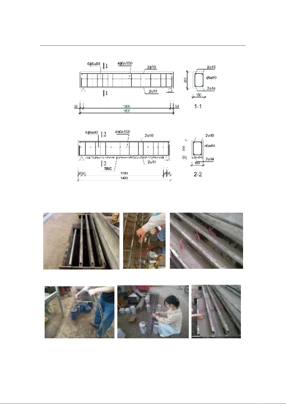
(RC) beams strengthened with textile-reinforced concrete (TRC). Four RC beams were made
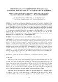
of B22.5 grade concrete, and the TRC strengthening layer utilized Sigratex Grid 350 textile,
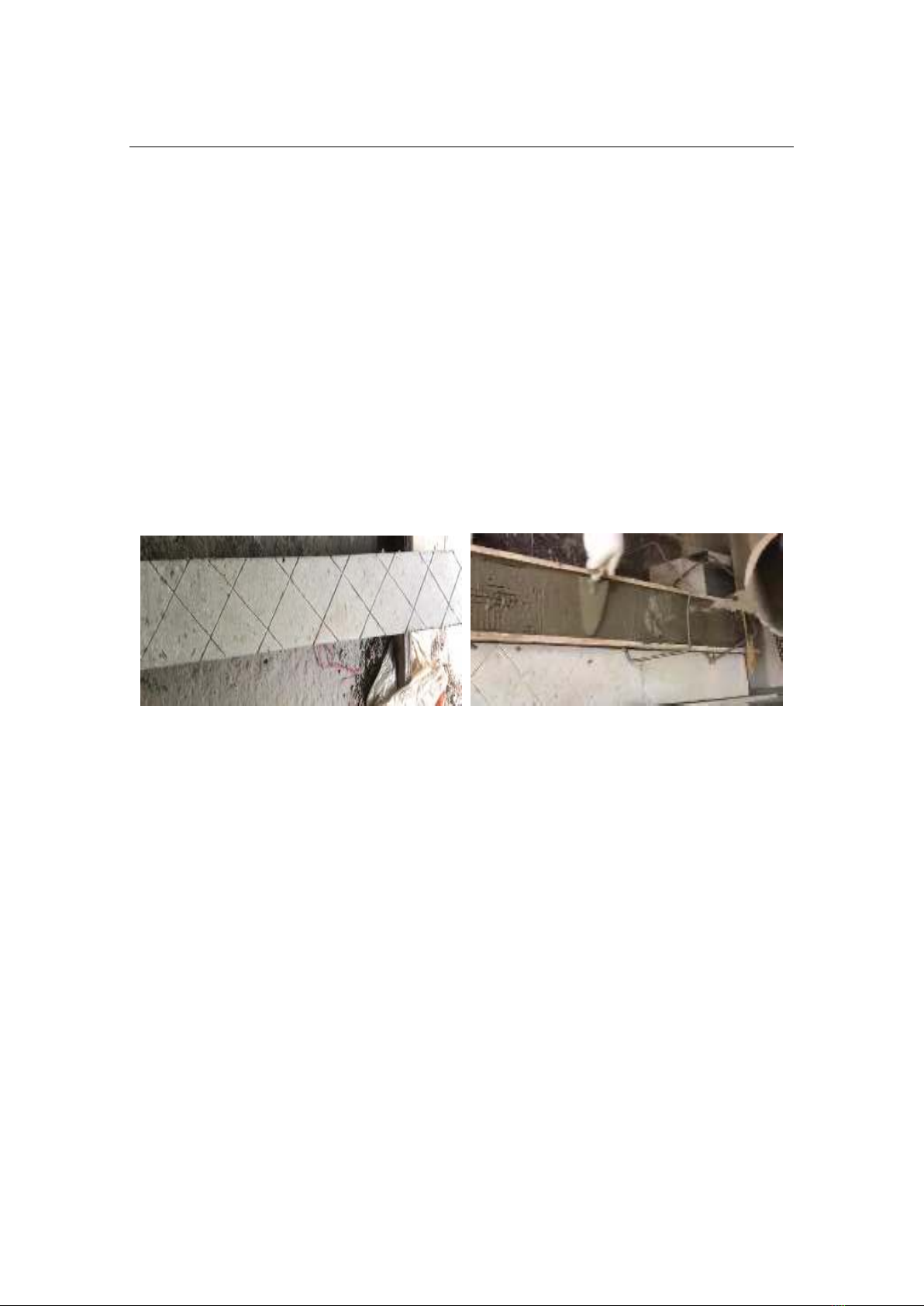
with fine-grained concrete Sikagrout 214-11 serving as the binder. The reinforcement layer was
applied using a grooving technique. The four-point bending test was conducted to evaluate the
improvements in load-bearing capacity and deformation of the beams after strengthening. The
results indicated that the strengthened beams exhibited a 36.2% higher load-bearing capacity
and a 13.5% increase in mid-span deflection compared to un-strengthened beams. However,
the occurrence of debonding in the reinforcing layer reduced the strengthening effectiveness.
To ensure the efficiency of flexural strengthening with TRC, attention should be given to the
adhesion of the fine-grained concrete layer and additional reinforcement of the compression
zone. These findings provide a basis for the practical application of TRC in enhancing RC
structures, ensuring both safety and performance.
Keywords: Textile reinforced concrete; strengthened reinforced concrete beam; four-point bending
test; grooving technique.
1. Introduction
Textile Reinforced Concrete (TRC) primarily consists of fine-grained concrete and
high-strength textile reinforcement, such as carbon or glass fiber. TRC exhibits superior
mechanical properties, high durability, and better corrosion resistance compared to
conventional concrete. TRC is used as a structural material and as a reinforcement to
enhance load-bearing capacity and extend the service life of structures [1, 2]. It is an
effective solution for improving the load-carrying capacity of reinforced concrete (RC)
beams, significantly increasing strength, initial cracking load, and ultimate load capacity,
enhancing ductility, and reducing environmental deterioration [3-5].
Experimental and numerical studies on flexural-strengthened beams have shown that
ensuring proper bonding between the TRC layer and the existing concrete is critical for
effective reinforcement. The adhesion between the fine-grained concrete layer and the old
* Corresponding author, email: maivietchinh@lqdtu.edu.vn
DOI: 10.56651/lqdtu.jst.v7.n02.885.sce
Section on Special Construction Engineering - Vol. 07, No. 02 (Dec. 2024)
186
concrete surface plays a decisive role in the success of the strengthening solution [6-9].
Therefore, the construction techniques for applying TRC layers to RC beams must be
carefully considered. Several methods to enhance the bond between TRC and old concrete
include surface roughening and grooving to increase friction between the two layers [5, 10];
the use of bonded anchors and studs to reduce the risk of slippage and delamination
between the TRC and concrete [11]; applying U-wraps at the ends, combined with surface
bonding, to increase the durability of the TRC-concrete bond [12]; combining external
reinforcement with near-surface mounting techniques [13]; and mixing fibers into the
matrix to prevent interlayer slippage, a common failure in TRC systems [11].
Among these methods, surface roughening and grooving are cost-effective and easy
to implement, making them the most common approach. However, when applied under
real-world conditions, this method still requires experimental validation to verify its
effectiveness. The objective of this study is to assess the effectiveness of using TRC as a
means of enhancing the load-bearing capacity of RC beams when following the grooving-
based strengthening method. The research focuses on evaluating the initial cracking load,
ultimate load capacity, and mid-span deflection of TRC-strengthened RC beams to
determine the method’s efficiency and provide recommendations for practical applications.
2. Flexural test
2.1. Materials for beam fabrication
The RC beams were constructed using conventional B22.5 concrete. For TRC-
strengthened RC beams, fine-grained concrete Sikagrout 214-11 was employed, while the
strengthening material consisted of textile fibers designated as Sigratex Grid 350. The
casting of beams was performed concurrently with the preparation of standard specimens
to evaluate the mechanical properties of both types of concrete. The material properties
of the carbon fiber textile (Sigratex Grid 350) and steel were provided by the
manufacturer. Detailed mechanical properties of the materials are summarized in Table 1
and 2.
Table 1. Material parameters for two types of concrete and fiber
Concrete types
c
f
(MPa)
t
f
(MPa)
E
(MPa)
(kg/m3)
Normal-weight concrete for slabs (B22.5)
39.5
4.1
29540
0.20
2320
Fine aggregate concrete Sikagrout 214-11
74.6
15.2
32600
0.18
2400
Bare fiber bundles Sigratex Grid 350
-
3550
225000
0.22
1740
Journal of Science and Technique - ISSN 1859-0209
187
Table 2. Mechanical properties of steel
s
E
(GPa)
s
Longitudinal Reinforcement AII
Stirrups AI
y
f
(MPa)
u
f
(MPa)
y
f
(MPa)
u
f
(MPa)
200
0.3
293
385
235
345
2.2. Sample preparation process
The experimental program involves testing four simply supported reinforced
concrete beams. Among these, two beams serve as the reference and are tested until
failure for comparison purposes. All beams share identical dimensions and reinforcement
details, with a total length of 1400 mm, an effective span of 1300 mm, a width of
150 mm, and a height of 200 mm. For the reinforced concrete beams subjected to bending,
failure is primarily caused by moments. Therefore, the stirrups at both ends of the beam
are designed with a spacing of approximately 80 mm, while the spacing in the middle
region is set at 150 mm to ensure that the beam fails primarily due to bending rather than
shear forces. The schematic layout of the beams and the reinforcement details are
illustrated in Fig. 1(a). According to the ACI 549.4R-13 technical guidelines, the TRC
layer is applied to the underside of the beam, covering the entire beam width (150 mm)
and extending along the full length of the beam, excluding the support regions (1000 mm).
The thickness of the TRC layers is 30 mm (typically ranges from 20 to 40 mm, depending
on the length of the beams). The detail of TRC-strengthened beam can be seen in
Fig. 1(b). The properties of the test specimens prepared for the flexural test are
summarized in Table 3.
Table 3. Characteristic of beam specimens
Specimen ID
Specimen
dimensions (mm)
TRC strengthening
dimensions (mm)
Number
of TRC
layers
Number
of
specimens
DO1-1
1400 × 200 × 150
No
DO1-2
1400 × 200 × 150
No
DO2-1
1400 × 200 × 150
Yes, 1200 × 150 × 30
1
1
DO2-2
1400 × 200 × 150
Yes, 1200 × 150 × 30
1
1
Figure 2 and 3 illustrate the process of fabricating unreinforced and reinforced
concrete beams. The reinforced concrete beams are strengthened with TRC following
these steps:
- The reinforced concrete beams are cured for 28 days before applying the
strengthening materials.
Section on Special Construction Engineering - Vol. 07, No. 02 (Dec. 2024)
188
(a)
(b)
Fig. 1. Schematic layout of the beam specimens:
a) Unreinforced bending beams; b) TRC-strengthened beam.
Fig. 2. Fabrication of RC beams (150 × 200 × 1400 mm).
Fig. 3. Casting concrete samples, reinforcing steel, and finishing the surface of the beams.
Journal of Science and Technique - ISSN 1859-0209
189
- A concrete cutting machine is used to create grooves on the surface of the beam
at the locations where the strengthening layer will be applied to enhance the bond between
the two material layers. First, the surface was moistened with water spraying. Then, the
surface grooving technique employs grinding and grooving tools to create grooves with
a depth of 2-3 mm and a spacing of 5 cm, as described in reference [5]. Accordingly, the
grooves are placed in two perpendicular directions, angled at 45 degrees to the main axis
of the beam's bottom surface (Fig. 4).
- The surface is cleaned with compressed air and dampened with water before
applying the strengthening layer.
- A layer of TRC strengthening material is adhered to the entire underside of the
beam, with a total thickness of 30 mm. The textile mesh is positioned centrally within the
strengthening layer.
Fig. 4. Cleaning, roughening the surface, and applying the TRC layer.
2.3. Testing procedure and equipment for bending beams
Experiments were conducted on both unreinforced and reinforced concrete beams.
To prevent the beams from slipping off the two supports and to ensure that the tensile
reinforcement does not pull out of the concrete during testing, both ends of the beam were
supported deep into the supports by 50 mm, and the reinforcement was anchored within
the concrete. The experimental setup consisted of a simply supported beam (one fixed
support and one movable support) subjected to the action of two concentrated forces,
denoted as P. The positions of the applied forces and the beam supports are illustrated in
Fig. 5, 6.
A hydraulic jack (20-ton capacity) is used in conjunction with a distributed loading
beam, where the concentrated load at the jack head is divided into two equal loads, P,
applied to the beam (Fig. 7). The value of the concentrated load at the jack head is
determined using a load cell connected to a Data Logger TDS 530 (manufactured by
Tokyo Sokki, Japan).