
ISSN 1859-1531 - THE UNIVERSITY OF DANANG - JOURNAL OF SCIENCE AND TECHNOLOGY, VOL. 22, NO. 11B, 2024 63
FLEXURAL CAPACITY CALCULATION OF RC BEAMS STRENGTHENED
WITH PRESTRESSED CFRP SHEETS
Nguyen Dang Dai Nam1, Ho Manh Hung1*, Doan Cong Chanh1,2, Phan Hoang Nam1,
Nguyen Minh Hai1, Gianluca Quinci3
1The University of Danang - University of Science and Technology, Danang, Vietnam
2School of Engineering, Tra Vinh University, Tra Vinh, Vietnam
3Roma Tre University, Rome, Italy
*Corresponding author: hmhung@dut.udn.vn
(Received: September 08, 2024; Revised: October 09, 2024; Accepted: October 15, 2024)
DOI: 10.31130/ud-jst.2024.522E
Abstract - This paper investigates flexural behavior and
analytical approach for predicting the load and deflection at
critical performance points of reinforced concrete (RC) beams
strengthened with prestressed carbon fiber-reinforced polymer
(CFRP) sheets. A finite element model is developed to simulate
the interaction between the RC beam and the CFRP sheets,
capturing key aspects such as failure modes, ultimate load, and
mechanical behavior across the three phases of failure. The
analysis reveals that increasing the prestress level significantly
enhances the performance, delaying the initiation of cracking,
steel yielding, and increasing the ultimate load capacity. Two
distinct failure modes are identified, i.e., concrete crushing in the
compressive zone and composite plate peeling. An analytical
approach is then proposed to estimate the load corresponding to
initial cracking, steel yielding, and ultimate failure. Comparison
between the experimental, numerical and analytical results shows
that the proposed method accurately predicts the flexural capacity
of RC beams strengthened with prestressed CFRP sheets.
Key words – Prestressed; CFRP sheets; FEM; analytical
approach; flexural performance
1. Introduction
Over time, structures gradually exhibit signs of aging,
leading to a decrease in their load-bearing capacity.
Moreover, factors such as external environmental impacts
and working under overload conditions further accelerate
the degradation in the quality of structures [1]. Especially in
reinforced concrete (RC) structures, the most common type
of structure today, which is highly susceptible to
environmental effects such as corrosion and abrasion due to
erosion in coastal and river areas. Numerous strengthening
methods for weakened positions have been proposed. Over
the past decade, the use of external strengthening materials,
such as steel plates, concrete, high-performance concrete,
ultra-high-performance concrete, and fiber-reinforced
polymer (FRP) composites, has become widespread. Among
these, FRP stands out for its advantages, continuously
affirming its superior properties, such as lightweight, high
tensile strength, and corrosion resistance, and it is
increasingly being applied [2].
The versatility and adaptability of FRP materials are
key advantages. Different fiber types offer specific
properties suited for various applications. Aramid fiber
reinforced polymer (AFRP) provides high elongation,
glass fiber reinforced polymer (GFRP) is a cost-effective
option with good thermal resistance, carbon fiber
reinforced polymer (CFRP) delivers exceptional tensile
strength and stress resistance, while basalt fiber reinforced
polymer (BFRP) offers stable properties. With this range
of FRP options, numerous studies have demonstrated their
benefits in enhancing load-bearing capacity, delaying
crack initiation, ensuring durability in harsh environments,
and providing economic efficiency [3, 4].
However, a significant issue is the bonding process,
where flexible FRP sheets, typically supplied in rolls, must
be carefully applied to weakened structural areas. This
process demands technical expertise, precision, and
advanced construction methods. Poor execution or design
can compromise FRP performance, particularly due to
stress relaxation, which diminishes the effectiveness of the
sheets during initial loading. To address this, prestressed
FRP sheets are tensioned before bonding to the structure,
providing a more efficient solution [5-7], though this
method is still influenced by several factors.
Recent global research has focused on this issue. A
series of experimental studies have evaluated the behavior
of RC beams strengthened with prestressed FRP sheets to
assess the impacts of various influencing factors. Notable
examples include the effect of anchorage systems on
prestressed FRP-strengthened RC beams [8-10], or the
efficiency of different prestressed FRP materials, such as
high-modulus CFRP (HM-CFRP), high-strength CFRP
(HS-CFRP), and composite basalt and steel fibers (SW-
BFRP) [11-13]. Additionally, the level of prestress applied
to the FRP sheets is also a key focus. A variety of factors
have been identified as having a significant influence on
the effectiveness of prestressed FRP strengthening. On the
other hand, aside from costly, time-consuming
experimental studies that struggle to consider a wide range
of reinforcement scenarios, numerical methods have also
been applied and show great potential. Numerical studies
are increasingly being improved, providing high accuracy
and addressing challenges in numerical modeling. For
example, Hu et al [14] solved the FRP-concrete interface
problem using a cohesive model, while another study by
Hawileh et al [15] used a spring element method to model
this bond. Obidat et al [16] compared these methods with
cohesive element methods to assess the pros and cons of
different models. However, these studies remain
fragmented and lack comprehensiveness as they primarily
64 Nguyen Dang Dai Nam, Ho Manh Hung, Doan Cong Chanh, Phan Hoang Nam, Nguyen Minh Hai, Gianluca Quinci
simulate specific scenarios, without fully reflecting the
impact of various design parameters on the flexural
performance of prestressed FRP-strengthened structures.
This study aims to explore the flexural behavior of RC
beams strengthened with prestressed CFRP sheets using
numerical methods. A FEM is developed and validated, with
a focus on the interaction between the CFRP and the
concrete beam, to assess the mechanical behavior, flexural
performance, and crack development in beams strengthened
with both prestressed and non-prestressed CFRP sheets.
Based on the analysis, critical points in the performance of
the strengthened beams are identified, and an analytical
approach is proposed to calculate the load and deflection of
RC beams reinforced with prestressed CFRP sheets.
2. Numerical modeling
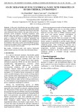
2.1. Description of case study
Three RC beam specimens presented in the previous
experimental study of the authors were selected as the
validation for the numerical analysis [17, 18]. The
dimensions of the beams are detailed in Figure 1. Among
these beams, one is an RC beam without prestressing,
serving as a reference beam. The second beam is reinforced
with a CFRP sheet but without prestressing (RC-CFRP-
PR0), while the remaining beam is reinforced with a CFRP
sheet prestressed to 500 MPa.
Figure 1. The parameters of RC beams
The compressive strength of the concrete was determined
from standard specimens with dimensions of 150x150x150
mm, cured for 28 days with the average compressive strength
for a set of 5 specimens was 35 MPa. The main tensile
reinforcement consisted of steel bars with a diameter of
14 mm (D14), while the compressive reinforcement had a
diameter of 8 mm. The yield strength and ultimate tensile
strength of the D14 steel bars were determined from tensile
testing, at 500 MPa and 720 MPa, respectively.
The CFRP sheets of the Sika CarboDur S1012 had a
width of 100 mm and a thickness of 1.2 mm. The tensile
strength and elastic modulus of the CFRP sheets were
3400 MPa and 165 GPa, respectively. The Sikadur-30
epoxy resin was used to bond the CFRP sheets to the
concrete surface. The tensile strength of the Sikadur-30
adhesive after 7 days was measured at 3.5 MPa. A load of
60 kN was applied to the CFRP sheet in the experimental
specimen, corresponding to approximately 15% of the
tensile strength of the CFRP sheet.
The beam specimens were tested using a four-point
bending setup with gradually increasing loads until failure.
The flexural behavior was evaluated at three key points:
(i) flexural cracking, (ii) reinforcement yielding, and
(iii) ultimate failure.
2.2. FEM development
A three-dimensional finite element model is introduced
to simulate the flexural behavior of RC beams reinforced
with FRP sheets using ABAQUS software [18, 19]. The
model is set up with input parameters corresponding to
those used in the previously mentioned experiment. The
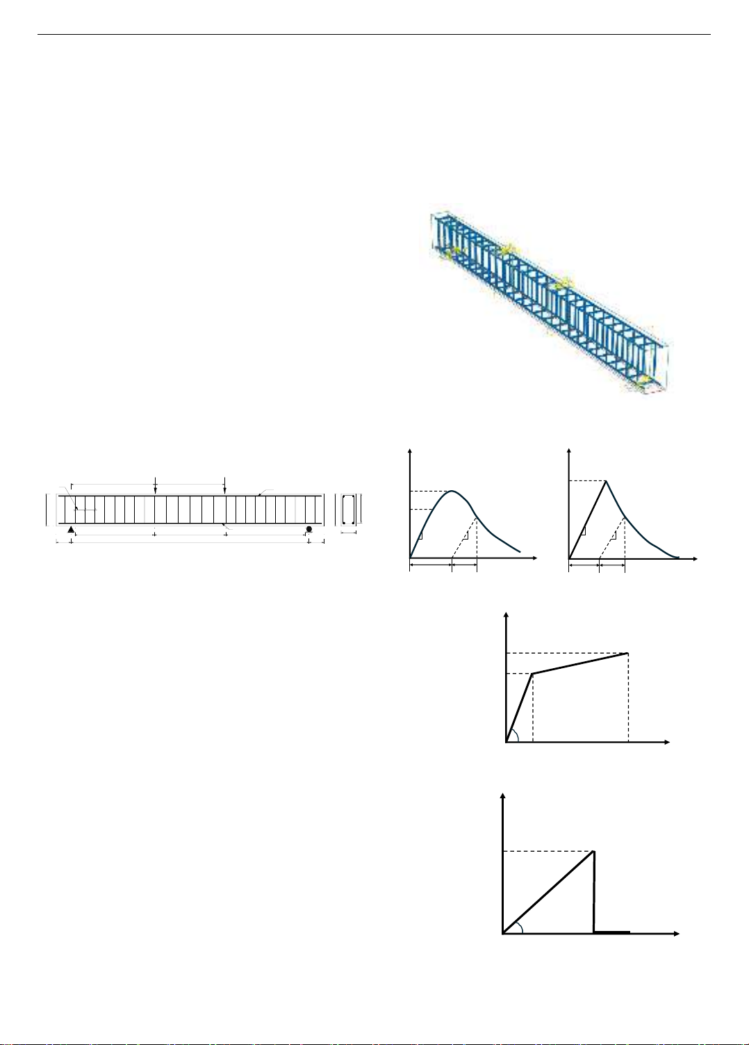
general model is illustrated in Figure 2. Concrete is
assigned using solid elements capable of three-dimensional
deformation, truss elements are used for the steel
reinforcing bars deforming along their axis, and shell
elements are assigned to the CFRP sheets with in-plane
deformation capability.
Figure 2. FEM model with the presence of reinforcements,
concrete beam, and CFRP sheet
(a) Concrete model
(b) Steel model
(c) FRP model
Figure 3. Material models
300
150 2400
130
150
P/2 P/2
2-D14
2-D8
6 x1208 x100 8 x100
850 700
D8
280
300
ISSN 1859-1531 - THE UNIVERSITY OF DANANG - JOURNAL OF SCIENCE AND TECHNOLOGY, VOL. 22, NO. 11B, 2024 65
Table 1. Material parameters used in the FEM model
Concrete
Compressi
ve strength
(MPa)
Tensile
strength
(MPa)
Young
modulus
(MPa)
Poisson
ratio
Density
(kg/m3)
35
2
30000
0.15
2450
Dilation
angle
Eccentrici
ty
Equibiaxi
al to
uniaxial
initial
yield ratio
Tensile
to
compress
meridian
s slope K
Viscosity
35
0.1
1.16
0.667
0.00005
Steel
Young
modulus
(MPa)
Poisson
ratio
Yield
strength
(MPa)
Tensile strength
(MPa)
200000
0.3
500
720
CFRP
Young modulus (MPa)
Tensile strength (MPa)
165000
3400
Regarding materials, the concrete damaged plasticity
(CDP) model [20] is employed to simulate the failure of
concrete in both tension and compression regions (Figure
3(a)). For steel, the bilinear model is used, with parameters
such as yield strength, ultimate strength, and the slope of
the yield plateau obtained from tensile testing of steel
(Figure 3(b)). Due to the characteristics of CFRP material,
a simple material model is described through a linear
relationship, where, upon reaching the tensile failure
strength, the CFRP breaks, and the stress drops to zero
(Figure 3(c)). A summary of material parameters is shown
in Table 1.
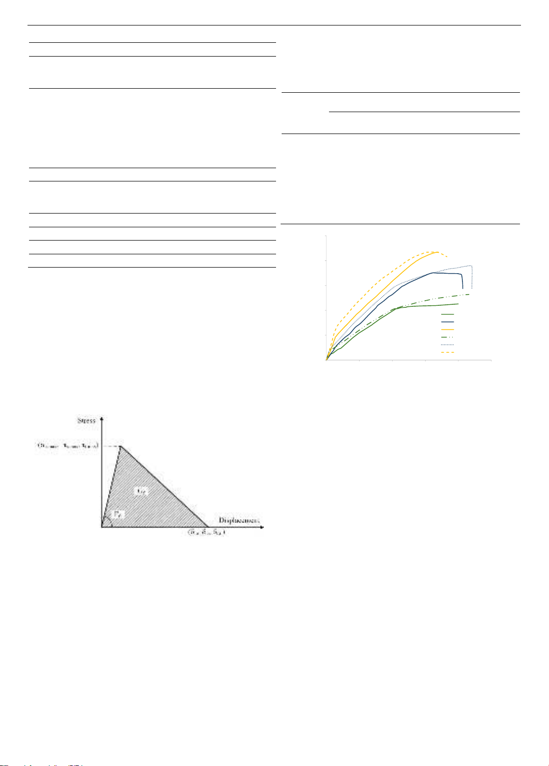
Figure 4. Bond-displacement relationship in the cohesive
model between concrete and FRP sheet
The initial stress method is used, applying a prestress
directly to the CFRP sheet [19]. The steel-concrete bond is
modeled using a hard contact that has been proven to be
highly reliable in previous studies [21]. A cohesive
behavior model is introduced to describe the complexity of
the concrete-CFRP bond interaction [16, 22, 23].
Specifically, the cohesive behavior model [14, 24] allows
for the definition of the bond through initial stiffness,
normal and shear bond strengths, with the characteristics
determined based on the technical parameters of the
Sikadur-30 epoxy resin. The initial stiffness is set
according to the elastic modulus of the epoxy adhesive, at
4.5 GPa, while the bond strengths in the normal and shear
directions are 3.5 MPa and 7.0 MPa, respectively.
With the simple geometric features of the beam
components, the automatic meshing function was
employed. The mesh edge lengths were set to 40 mm,
25 mm, and 20 mm, respectively.
Table 2. Comparison between experiment and simulation results
Specimens
Flexural crack
Reinforcement
yielding
Ultimate
failure
𝑷𝟏𝑬𝒙𝒑
(kN)
𝑷𝟏𝑺𝒊𝒎
(kN)
𝑷𝟐𝑬𝒙𝒑
(kN)
𝑷𝟐𝑺𝒊𝒎
(kN)
𝑷𝟑𝑬𝒙𝒑
(kN)
𝑷𝟑𝑺𝒊𝒎
(kN)
RC
12.3
15.3
103.5
104.5
109.6
116.1
Exp/Ana
0.80
0.99
0.94
RC-CFRP-
PR0
15.2
18.0
150.0
151.6
175.6
184.7
Exp/Ana
0.84
0.99
0.95
RC-CFRP-
PR500
46.3
53.4
198.8
208.2
217.7
217.4
Exp/Ana
0.87
0.95
1.00
Figure 5. Comparison of the load-deflection relationship
between experiment and simulation
The numerical analysis results are presented in Figure
5 and summarized in Table 2 together with the previous
experimental results. It is noticed that the simulated beam
models were labeled with the prefix "S”, representing
simulation. In general, the simulation results show a high
degree of agreement with the experimental results. Firstly,
for the point at which the first flexural crack appears, the
ratio between experimental and simulated values ranges
from 0.8 to 0.87. Next, the ratio between the experimental
and simulated values at the yield point of the reinforcing
steel ranges from 0.95 to 0.99. Moreover, for the ultimate
failure point of the beam, this ratio fluctuates between 0.94
and 1.0. These findings demonstrate that the model
performs well in simulating post-crack behavior, closely
capturing the behavior and load-bearing capacity of CFRP-
reinforced beams in the experiment.
Specifically, for the beam model S-RC-CFRP-PR500,
the correlation is very high at all three critical points. At
the flexural crack initiation point 𝑃1, the experimental
result is 46.3 kN, while the simulated result is 53.4 kN
(≈87%). At the yield point of the reinforcing steel 𝑃2, the
experimental and simulation results are 198.8 kN and 208.2
kN, respectively (≈95%). For the ultimate failure state 𝑃3
or 𝑃 , these results are 217.7 kN and 217.4 kN (≈100%),
respectively. This high level of correlation shows that, after
the initial crack formation stage, the simulation results
almost perfectly align with the experimental results.
0
50
100
150
200
250
0 5 10 15 20 25
Load (kN)
Deflection (mm)
RC
RC-CFRP-PR0
RC-CFRP-PR500
S-RC
S-RC-CFRP-PR0
S-RC-CFRP-PR500
66 Nguyen Dang Dai Nam, Ho Manh Hung, Doan Cong Chanh, Phan Hoang Nam, Nguyen Minh Hai, Gianluca Quinci
3. Analytical model development
3.1. Analysis of performance phrases of beams based on
numerical results
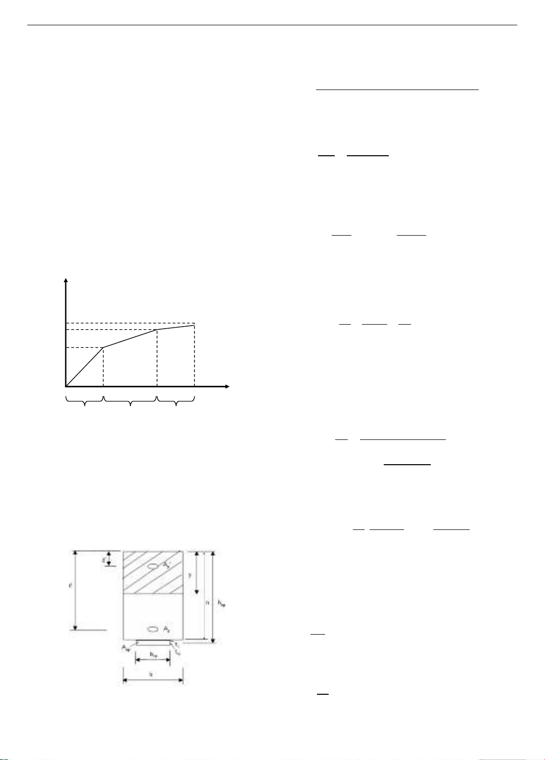
The behavior of RC beams reinforced with prestressed
FRP sheets can be divided into three stages: (i) the elastic
stage, (ii) the crack development stage, and (iii) the elastic-
plastic stage, as illustrated in Figure 6.
In the elastic stage, the concrete is uncracked, and the
deflection increases linearly with the load. The load 𝑃1
corresponds to the point at which flexural cracks first appear
in the concrete. The stiffness in this stage is denoted as 𝛼1.
In the crack propagation stage, the cracks in the concrete
begin to widen and develop. The tensile reinforcement
remains in the elastic region until it reaches the load 𝑃2,
which corresponds to the yield stress of the steel at the
maximum bending section. The stiffness in this stage is
denoted as 𝛼2. In the third stage, the concrete is fully
cracked, the tensile reinforcement yields, and the failure
region progresses toward the ultimate failure, with the
corresponding load referred to as the ultimate load 𝑃3 or 𝑃 .
Figure 6. Different stages of the mechanical behavior of the beam
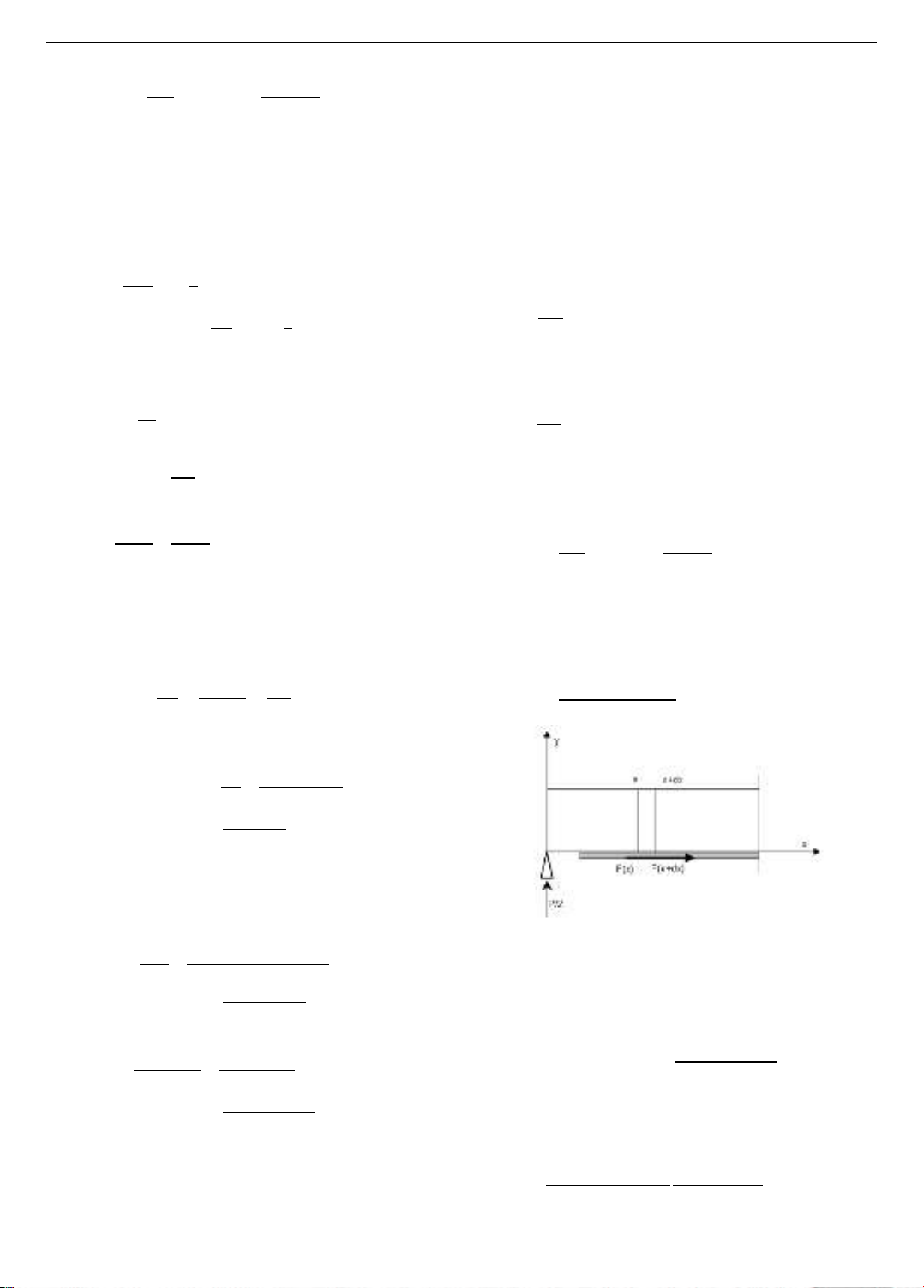
3.2. Analytical model development
A theoretical analytical model based on equilibrium
equations is developed in this section to describe the
behavior of reinforced concrete beams (RC beams) under
bending, strengthened with prestressed FRP sheets. The
model is based on cross-sectional parameters and material
properties. On this basis, the stresses at the fibers of the
cross-sectional area at different stages are calculated
through the mechanical behavior of the beam.
Figure 7. Cross-section of the concrete beam reinforced with
CFRP sheets
Stage 1: In this stage, the concrete is uncracked. All
materials are homogeneous within a concrete cross-
section. The position of the neutral axis can be calculated
by transforming the forces within the homogeneous section
(Figure 7),
𝑦=[ ′𝐴𝑠′ + 𝐴𝑠 + 𝐴 + + /2 +𝑏 2/2
𝐴𝑠
′+𝐴𝑠 + 𝐴 +𝑏
(1)
Considering the effects of reinforcement and FRP sheets,
the moment of inertia of the equivalent section can be
calculated as
𝐼 =𝑏𝑦3
3+𝑏 𝑦 3
3+ 𝐴𝑠 𝑦 2
+ 𝐴 𝑦 2
(2)
In the elastic stage, the load-deflection relationship is
governed by the equation
𝑃1=𝛼1𝐷1
(3)
where 𝛼1=𝐸𝑏𝐼𝑛𝑓
and 𝑐 = 3𝐿2−4𝑎2
48
(4)
with a being the distance from the support to the load point
and L is the span length.
When the beam is subjected to bending under the load
and the prestressing force of the FRP sheet, the stress at the
top and bottom fibers of the section is given by
𝑦 = 𝐹
±𝐹 𝑦
𝐼∓𝑀𝑦
𝐼
(5)
where is the distance between the neutral axis and the
FRP sheet, 𝐹 is the prestressing force of the FRP sheet,
and is the section modulus of the concrete, with
compression being denoted as negative (-) and tension as
positive (+). When flexural cracks appear, the tensile stress
at the bottom fiber of the section reaches the tensile
strength limit of the concrete. From equation (5), we have
𝑓′ = 𝐹
𝑏 𝐹 ( 𝑦) 𝑦
𝐼
+𝑃1 𝑦
2𝐼
(6)
After a simple transformation, the load 𝑃1,
corresponding to the initial cracks in the concrete, can be
evaluated by the equation,
𝑃1=2 𝑓′ +𝐹
𝑏 𝐼
𝑦 +2𝐹 𝑦
(7)
where 𝑓′ is the tensile strength limit of the concrete.
Stage 2: In this stage, the calculation of the neutral axis
position is performed by the static equilibrium of the
homogeneous section, neglecting the influence of the
tensile concrete. The position of the neutral axis is the
solution to the equation
0=𝑏𝑦2
2+ 𝐴𝑠
′ 𝑦 ′ + 𝐴𝑠 𝑦
𝐴 ( 𝑦).
(8)
The moment of inertia of the homogeneous section can
be calculated using the general formula
𝐼=𝑏𝑦3
3+ 𝐴𝑠
′ 𝑦 ′ 2+ 𝐴𝑠 𝑦 2
𝐴 𝑦 2.
(9)
The load-deflection relationship is determined by
Load
𝑃3
𝑃2
𝑃1
𝐷3
𝐷2
𝐷1Deflection
Elastic
stage
Crack development
stage
Elastoplastic
stage
ISSN 1859-1531 - THE UNIVERSITY OF DANANG - JOURNAL OF SCIENCE AND TECHNOLOGY, VOL. 22, NO. 11B, 2024 67
∆𝑃=𝛼2∆𝐷,
(10)
where 2=𝐸𝑏𝐼𝑓
and c = a 3𝐿2−4𝑎2
48
(11)
It is assumed that the moment of inertia of the section
does not change along the beam. However, under bending
loads, the section remains uncracked in the region 𝑥<𝑥𝐶
(the position at the cracking moment 𝑀𝐶 ) and cracked in
the region 𝑥 >𝑥𝐶 . Considering the uncracked (with 𝐼𝑛𝑓)
and cracked regions (with 𝐼𝑓), a new expression for
deflection can be obtained using equation (12),
D =2[
𝐼𝑛𝑓 ∫𝑥
2𝑀 𝑥 𝑥
𝑥𝐶𝑅
]
+
𝐼𝑓∫𝑥
2𝑀 𝑥 𝑥
𝐿−𝑥𝐶𝑅
𝑥𝐶𝑅
(12)
For four-point bending, the bending moment 𝑀 𝑥 is
calculated as
M x =𝑃𝑥
2
(13)
The concrete remains uncracked when 0<𝑥<𝑥𝐶
and 𝑥𝐶 =2𝑀𝐶𝑅
Then, equation (12) becomes
D= 𝑃𝑥𝐶
3
6 𝐼𝑛𝑓 +𝑃
48 𝐼𝑓[ 3𝐿2 4 2 8𝑥𝐶
3]
(14)
The load 𝑃2 corresponding to the yielding of the tensile
reinforcement, and the corresponding deflection 𝐷2 are
calculated according to equation (3.14). In general, the
stress at the bottom fiber of the homogeneous concrete
section can be relatively calculated as
σ 𝑦 = 𝐹
𝐹 𝑦
𝐼+𝑀𝑦
𝐼
(15)
For steel in the tensile region, 𝑦= 𝑦 , equation
(15) can be rewritten as
σ( d y )=n( 𝐹
𝐹 𝑦
𝐼
+𝑀 𝑦
𝐼)
(16)
When the steel yields, the stress in the steel equals the
yield strength 𝑓𝑦𝑘. From equation (16), the load 𝑃2,
corresponding to the yielding of the tensile steel, can be
evaluated by the equation
𝑓𝑦𝑘 = 𝐹
𝑏 𝐹 ( 𝑦) 𝑦
𝐼
𝑃2 𝑦
2𝐼
(17)
Therefore
𝑃2= 2𝐼𝑓𝑦𝑘
𝑦 +𝐹 2𝐼
𝑏 𝑦
2𝐹 ( 𝑦)
(18)
The deflection corresponding to 𝑃2 is determined from
∆𝐹2 and 𝐹2
𝐷2=𝐷1+∆𝐷2
Stage 3: In this stage, the tensile reinforcement (𝐴𝑠)
operates in the plastic region and strain-hardening region;
hence, a new modular ratio ′ is applied. The value of ’ is
calculated as the ratio between the modulus of elasticity in
the strain-hardening region of the steel and the elastic
modulus of the concrete. This ratio is significantly smaller
than in the elastic stage; therefore, the contribution of the
tensile reinforcement to the stiffness of the section is
significantly reduced in stage 3.
The position of the neutral axis is calculated as in stage
2, considering the modular ratio ’ for the tensile
reinforcement (assuming that the strain-hardening region is
linear). As a result, there is a solution to the equation
0=𝑏𝑦2
2+ 𝐴𝑠
′ 𝑦 ′ + ′𝐴𝑠 𝑦
𝐴 𝑦
(19)
The moment of inertia of the homogeneous section in stage
3 is given by
𝐼=𝑏𝑦3
3+ 𝐴𝑠
′ 𝑦 ′ 2+ ′𝐴𝑠 𝑦 2
𝐴 𝑦 2
(20)
In stage 3, the load-deflection relationship is governed
by the equation
∆𝑃=𝛼3∆𝐷,
(21)
where 3=𝐸𝑏𝐼𝑓
and 𝑐 = 3𝐿2−4𝑎2
48 .
(22)
In a bending structure, the stress gradient in the FRP
sheet generates shear stress on the interface between the
FRP sheet and the concrete (Figure 8). Between two
sections separated by a distance 𝑥, the generated shear
stress is calculated as
𝜏 𝑥 =𝐹 𝑥+ 𝑥 𝐹 𝑥
𝑏 𝑥
(23)
Figure 8. Shear stress on the interface of
the FRP sheet and concrete
The stress in the FRP layer depends on the bending
moment of the section, therefore
𝑥 = 𝑥,𝑦 = ( 𝑦𝑓)
= 𝑀 𝑥 𝑦𝑓
𝐼𝑓
(24)
The tensile force is calculated as
𝐹 𝑥 = 𝑥 𝑏 .
(25)
Therefore, the shear stress at 𝑥 is calculated as
𝜏 𝑥 =𝑀 𝑥+ 𝑥 𝑀 𝑥
𝑏 𝑥 𝑦𝑓
𝐼𝑓𝑏
(26)
After simplification, equation (26) becomes


![Giáo trình Cấu trúc dữ liệu và giải thuật - Trường CĐ Cơ điện Hà Nội [Mới nhất]](https://cdn.tailieu.vn/images/document/thumbnail/2026/20260323/lionelmessi01/135x160/58171774381670.jpg)


![Giáo trình Tiện nâng cao (Nghề Cắt gọt kim loại, Trình độ Cao đẳng) - Trường Cao đẳng Cơ điện Hà Nội [Mới nhất]](https://cdn.tailieu.vn/images/document/thumbnail/2026/20260323/lionelmessi01/135x160/48101774403543.jpg)


