
* Corresponding author.
E-mail addresses: amitsinha5050@gmail.com (A. K. Sinha)
© 2016 Growing Science Ltd. All rights reserved.
doi: 10.5267/j.esm.2016.4.001
Engineering Solid Mechanics 4 (2016) 226-234
Contents lists available at GrowingScience
Engineering Solid Mechanics
homepage: www.GrowingScience.com/esm
Guillotine side trimming shear machine: A case study of plate mill in Bhilai steel
plant
Murli Krishan Bairagia, Amit Kumar Sinhab* and Ankush Anandb
aDepartment of Mechanical Engineering, National Institute of Technology, Srinagar, India-190006
bDepartment of Mechanical Engineering, Shri Mata Vaishno Devi University, Katra, India-182320
A R T I C L EI N F O A B S T R A C T
Article history:
Received 6 October, 2015
Accepted 23 April 2016
Available online
24 April 2016
Double-sided trimming shear machine is used for longitudinal both–sided trimming of steel
plates and simultaneous scraping of trimmed edges at specific length. Side trimming shear
(STS) executes the most vital role in increasing the productivity of plate mill and due to its
feature, efficiency of plate mill division is enormously increases. In general, frequency of the
occurrence of breakdown in STS machine is a most challenging task when STS performs side
trimming and scrap cutting machining process. Bhilai Steel Plant (Steel Authority of India at
Bhilai) in India is continuously facing a problem due to breakdown of STS machine. The use
of separate knife for side trimming and scrap cutting reduces the possibility of scrap jamming
which is a major reason for breakdown of STS machine. Researchers and practitioners also
suggest the use of arc guillotine shear for side trimming and straight guillotine shear for scrap
cutting for minimizing the breakdown in STS machine. The aim of this study is to describe the
problems faced by the steel industry as well as the necessary steps which should be taken for
improvement of the productivity of STS machine and also it has made contribution to Bhilai
Steel Plant by its growth and prosperity. The methodology of study is purely qualitative and
the results point out the problems, its implications, steps taken to improve the overall
productivity of Bhilai steel plant.
© 2016 Growing Science Ltd. All rights reserved.
Keywords:
Trimming mechanism
Bhilai steel plant
Kinematics of machine
Shear force
1. Introduction
Bhilai steel plant (BSP) was established with Indo-Russian collaboration on March 2, 1955
(Roberts, 1983) which is the India’s first and foremost manufacturing plant of steel plates as well as
steel rails. In the present scenario, BSP is the eleven-time winner of prime minister’s trophy for best
integrated steel plant in India, it (BSP) achieves fourth position in world among top steel producers
(Parry & Strümpell, 2008). Bhilai steel plant is one of the integrated steel plants of Steel Authority of
M. K. Bairagi et al. / Engineering Solid Mechanics 4 (2016)
227
India Limited (SAIL). BSP has all together 61 departments. Some of the important department of BSP
are as follows: Coke oven batteries, Blast furnaces, Steel melting shop, Research and control laboratory,
Blooming and billet mill, Merchant mill, Wire rod mill, Rail and structure mill, Plate mill, Coal
chemical plant, Dust catcher department, Cast house, Gas cleaning section, Foundry shop, Forging
shop, Continuous casting department, Oxygen plant, Propane plant, Sintering plant, Twin hearth
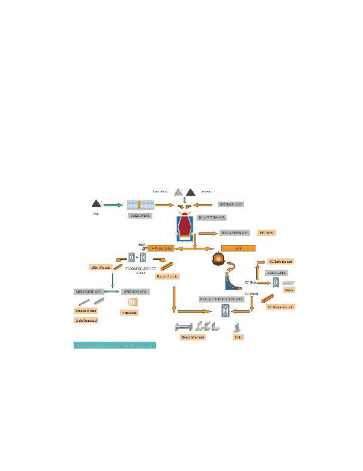
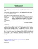
department, etc. Fig. 1 illustrates the process flow chart of BSP, SAIL (SAIL, 2015; Kashyap, 2014).
Out of 61 departments, Plate mill is one of the most important department. Side trimming shear (STS)
machine which is installed in Plate mill department is continuously utilizing for longitudinal both–
sided trimming of steel plates and simultaneous scraping of trimmed edges at specific length.
The productivity of Plate mill mainly depends upon the efficiency of STS machine. Therefore,
minimizing the non-productive time of STS machine is a major challenging task for BSP. Although,
there are a lots of reason for breakdown of STS machine but in this article we are mainly emphasizing
the scrap jamming which is a major factor for breakdown of STS machine. In BSP, occurrence of
frequent breakdown in STS machine decreases the productivity of Plate mill. Therefore, smooth
functioning of STS machine is a major concern for any practitioners and researchers.
In this article, we conducted descriptive and experimental research for dealing how to minimize
the breakdown in STS machine. The use of separate knife for side trimming and scrap cutting reduces
the chances of breakdown in STS machine. This article also reveals some of the major reasons which
are responsible for breakdown in STS machine.
Fig.1. Process flow chart of SAIL Bhilai adopted from SAIL (2015)
2. Literature survey
Scrap jamming in STS machine is a major concer for conducting the research for any researchers
and practitioner. Although, a lot of suggestions are suggested and some of the suggestion are
implemented by some of the industries. But, it is hard to conclude that we already elliminated the
possibility of scrap jamming in STS machine. Therefore, scrap jamming is a major concern for
improving the productivity of STS machine. Improved version of rotary drum type shearing machine
is discussed by Ito (1997) for cutting long hot rolled steel plate at very high speed. Moyer (1949)

228
suggested a trimming machine which is more useful for trimmimng three edges of folded, multi-page
booklet. Due to the above sugggested trimming machine papers and piles industries speedup
exponentially. The contribution of Elwood (1950) accelerated the cutting/trimming operations in a shell
drawn from a sheet metal. They implemented the concept of straight side wall haveing a sharp cutting
edge for performing the machining operation.
Sewing, circular shearing, and guillotine shearing are the three most important mechanicsms
which are utilized in metal tube industy for cutting metal tube. Although the most problem which is
associated with guillotine shear cutting mechanism for cutting metal tube is the happeing of the partial
crushing of the tube near the cutting-place and this partial crushing is responsible for occurrence of
slightly folding near the end of cut tube. The presence of this slight fold narrows the free opening of
the tube and impedes the introduction of balls during mounting on mandrel rods in cases where the two
tube sections are to be subsequently drawn. This disadvantage can be overcome by using the sawing
method, but saw cuttings adhering is a major challenging task in sawing mechanism for any
practitioners and researchers.
Marcel (1962) suggested a new concept for preventing the deformation of metal tube by doing
some improvement in guillotine shear cutting mechanism and they also found that due to this
advancement, there were no saw cutting left. The new advancement of Marcel (1962) consists of a
cutting tool which is utilized for cutting tool to use in shearing tube on guillotine shears. The salient
characteristics of Marcel (1962) cutting tool is that the shearing members make two half V’s which are
joined together but they maintain their point offset relative to each other. On the basis of empirical
relationship, it is quite clear that the points are offset by a distance at least equal to the wall thickness
of the metal tube.
Side-stand, hold-down, blade carrier, top connecting plate, and bottom connecting plate are the
major component of guillotine shear (Tozzo et al., 2014). The above suggested major components are
responsible for vibration characteristics, factor of safety, rigidity and strength, dynamic stresses of the
guillotine shear. Therefore, these components should be critically examined from time to time
(Ramamurti et al., 1997).
There is limited literature based on design of plate working machine tools (Zhang & Gao, 2014).
However, some scholars (Ramamurti et al. 1992 and 1994) explain the basic conceptual design of three-
roll plate bending machine and press brake of medium capacity. Ramamurti and Gowri (1996)
illustrated statistical analysis of guillotine shearing machine. Ramamurti et al. (1998) presented two
baisc model of guillotine shearing machines, first model based on the conceptual design with the drive
shaft paraller to the blade and the other is perpendicular to the blade.
3. Background of guillotine side trimming shear machine
Nowadays, steel is the fundamental key for economic growth of any nation. In India, there are
several steel manufacturers like Jindal Group, TATA Steel Group, JSW Steel Limited, Bhusan Steel
Corporate Limited, etc. But, Bhilai Steel Plant is one of the best integrated steel plants of SAIL in India.
Side Trimming Shear Machine is used for finishing the steel plates. It consist mainly four mechanism
by which, after shearing or trimming, we get desired width of steel plates (Wang et al., 2014). The four
most important mechanisms of STS machine are as follows (Boljanovic, 2014; Gustafsson &
Oldenburg, 2014):
- Counter Balance mechanism
- Vertical Gap mechanism
- Two-arm lever mechanism
- Horizontal Gap mechanism
M. K. Bairagi et al. / Engineering Solid Mechanics 4 (2016)
229
3.1 Counter balance mechanism
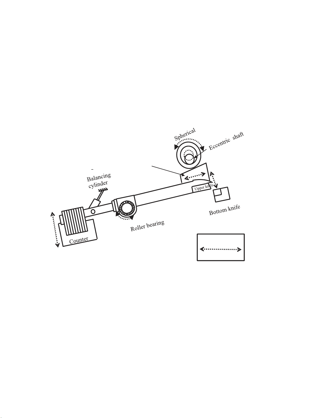
The schematic diagram of counter balance mechanism as well as vertical gap side trimming
mechanism is illustrated in Fig. 2. Eccentric shaft with spherical roller and upper knife with knife holder
act as a driver and driven systems, respectively. The driver is a major component of counter balance
and vertical gap side trimming shear machine (see Fig. 2). When eccentric shaft rotates due to this
spherical roller press the wedge goes downward. And, due to this downward force, one end of the
hollow shaft which is attached to wedge as well as upper knife will move downward. The other end of
the hollow shaft is attached with counter weight of approximate 500kg. The whole mechanism is
mounted on anti-friction bearing (roller bearing) which will facilitate for see-saw mechanism. In
counter balance mechanism the eccentric shaft that is driven by the bull gear is responsible for the
downward movement of the upper knife for side trimming. Now for the upward movement of the upper
knife we use a counter-weight which is attached at the other end of the shaft, connecting to the knife
lever.
Fig. 2. Counter balance and vertical gap side trimming shear mechanism
Above, we already understand the concept of counter weight mechanism. Now the question is why
we use counter weight for this specific mechanism? The answer is, there is no upward movement of
upper knife so if we attached a dead weight to other side of hollow shaft then due to gravity upper knife
will move upward and due to eccentric shaft upper knife will move downward. In Fig. 2, there is a
balancing (hydraulic) cylinder whose purpose is to smooth this mechanism by adjusting the
instantaneous pressure. So as the virtue of cutting force will be generate and cutting of steel plates takes
place.
3.2 Vertical gap mechanism
Before starting the discussion of vertical or horizontal gap mechanism of STS machine we first
understand the basic concept of horizontal and vertical gap. In this mechanism electric motor with
screwed lever act as a driver and wedge mounted on hollow shaft acts as a driven system. Horizontal
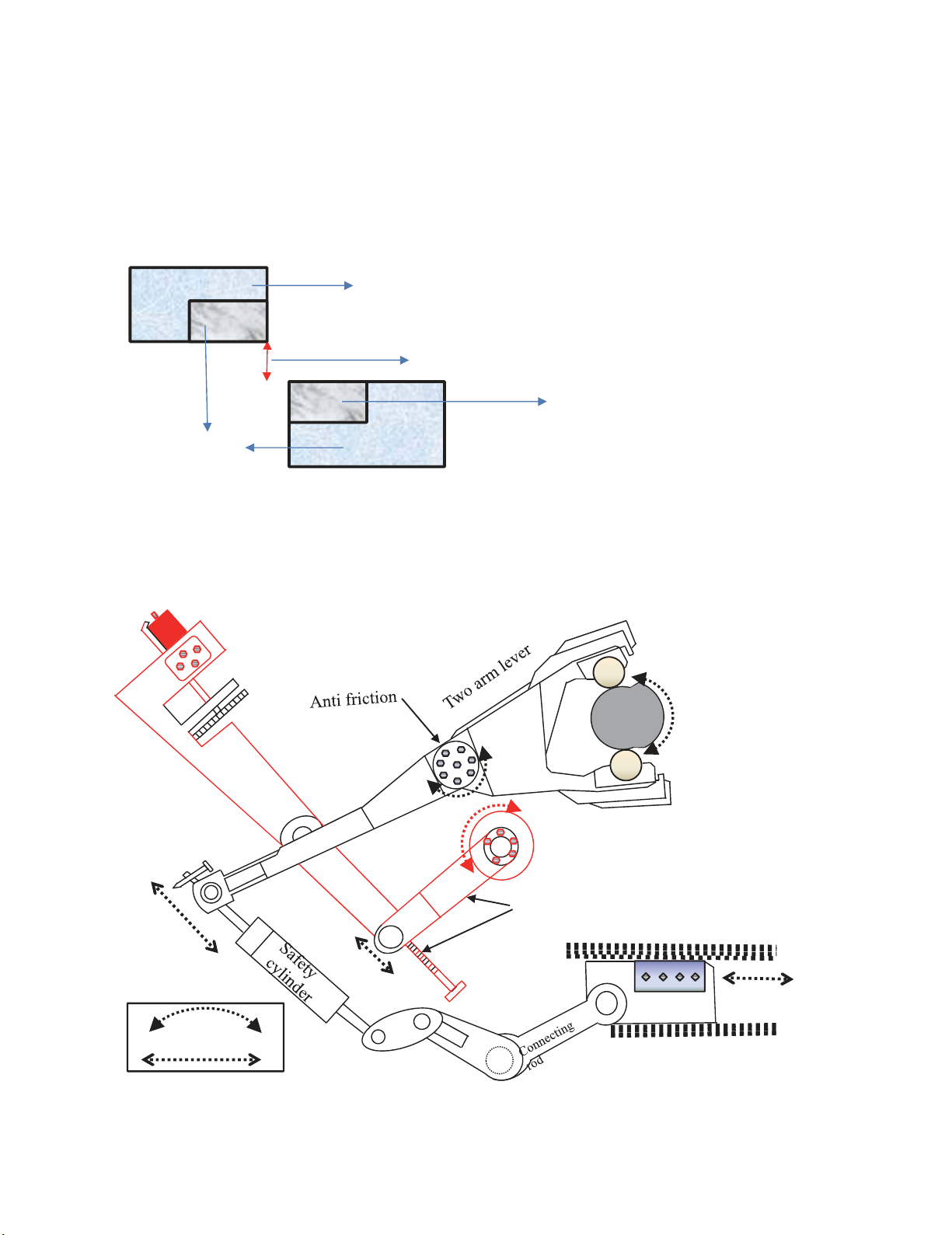
gap is the gap between the upper knife and bottom knife horizontally and vertical gap is the gap between
the upper knife and bottom knife vertically with the reference as cutting edge of bottom knife. Vertical
Direction of
motion
Motion of wedge responsible for
G
230
gap is illustrated in Fig. 3. Intentionally, we prove some oblique (3 to 4 degree) to upper knife with
respect to bottom knife. Due to this oblique cutting of steel plate take place. The reason behind for
providing some oblique is that this oblique decreases the point of contact in between upper and bottom
knife which increases the shearing pressure for cutting steel plate. We have already discussed about
vertical gap side trimming shear mechanism (shown in Fig. 2). Vertical gap is created by the motion of
wedge which is clearly illustrated in Fig. 3. Electric motor is attached with screwed lever and the
movement of this lever is creating horizontal movement of wedge. Due to the relative motion of wedge
and spherical roller (see Fig. 2), upper knife goes downward and this downward movement of knife
adjusts the vertical gap.
Fig. 3. Side view of cutting blades with vertical gap
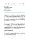
3.3 Two-arm lever mechanism
Fig. 4. Two-arm lever and horizontal gap side trimming shear mechanism
Vertical gap between upper and lower cutting blades (before cutting)
Upper knife
Bottom knife
Knife Holder
Motor
Reducer
Gear
Screwed
lever
Supporting shaft
Cam
1&2
Cross knife for scrap
cutting
Component responsible for
H.G.mechanism
Direction of
motion


![Sửa chữa và bảo dưỡng bơm trợ lực lái: Bài 5 [Hướng dẫn chi tiết]](https://cdn.tailieu.vn/images/document/thumbnail/2013/20130826/maivanchung/135x160/3041377498544.jpg)


![Đề thi Động cơ đốt trong kết thúc học phần: Tổng hợp [năm]](https://cdn.tailieu.vn/images/document/thumbnail/2026/20260320/hoabattu2026/135x160/24841774320014.jpg)


