38
Network
Economy
Measures zyxwvutsrqponmlkjihgfedcbaZYXWVUTSRQPONMLKJIHGFEDCBA
People who plan telecommunications networks are always searching for equipment economy
measures: reducing the cost of
a
network for
a
given information carrying capacity; or,
conversely, increasing the information throughput of a fixed network resource.
To
achieve their
aims, they can either maximize the electrical bandwidth available from
a
given physical
transmission path,
or
(if it is the other kind
of
economy they want) they can reduce the amount of
electrical bandwidth required to carry individual messages or connections. This chapter describes
a few of the practical economy measures open to them. zyxwvutsrqponmlkjihgfedcbaZYXWVUTSRQPONMLKJIHGFEDCBA
38.1 COST
MINIMIZATION
Reducing the cost of equipment required for a given information throughput is
important for public and private network operators alike; both will be keen to to reduce
the quantity and the cost of lineplant and switch gear.
If
a given resource, say a transmission link,
is
already laid on then there is not much to
be gained by applying economy measures which have the sole effect of making some of
the available capacity redundant. In such circumstances it may be advantageous to
‘squeeze’ extra capacity from the line, especially if it is nearing its limit. This can be valu-
able for one of three reasons; first, it enables expenditure on more capacity to be delayed;
second, it may be the only practicable means; or third, the cost of duplication may be
prohibitive. The first reason might postpone the need for a private network operator to
lease more capacity from the PTO (public telecommunication operator). The second
case might arise because of a need to make more telephone channels available from a
limited radio bandwidth. The third might reflect a lack of resources to finance the pro-
hibitive cost
of
a transatlantic undersea cable.
Earlier chapters in this book have covered one important means of lineplant
economy, that
of
bandwidth multiplexing, by either the (analogue) zyxwvutsrqponmlkjihgfedcbaZYXWVUTSRQPONMLKJIHGFEDCBA
frequency division
multiplex
(FDM)
method, or the (digital)
time division multiplex
(TOM)
method. This
chapter briefly recapitulates these two methods, and goes on to describe some other zyxwvutsrqponmlkjihgfedcbaZYXWVUTSRQPONMLKJIHGFEDCBA
695
Networks and Telecommunications: Design and Operation, Second Edition.
Martin P. Clark
Copyright © 1991, 1997 John Wiley & Sons Ltd
ISBNs: 0-471-97346-7 (Hardback); 0-470-84158-3 (Electronic)
696
NETWORK zyxwvutsrqponmlkjihgfedcbaZYXWVUTSRQPONMLKJIHGFEDCBA
ECONOMY
MEASURES
important techniques including zyxwvutsrqponmlkjihgfedcbaZYXWVUTSRQPONMLKJIHGFEDCBA
circuit multiplication equipment
(CME),
statistical
multiplexing
(used in data networks), speech interpolation,
low
rate encoding zyxwvutsrqponmlkjihgfedcbaZYXWVUTSRQPONMLKJIHGFEDCBA
(LRE)
and
differential or adaptive differential PCM (DPCM and ADPCM).
38.2
FREQUENCY
DIVISION
MULTIPLEXING
(FDM)
Frequency division multiplexing (FDM) provides a means of carrying more than one
telecommunications channel over a single physical analogue bearer circuit, as Chapter 3
records. FDM relies
on
the carriage of a large electrical bandwidth over the circuit.
Bandwidth for individual telecommunications channels is made available by sub-
division of the overall bandwidth, much as some main roads are marked out into a
number of lanes. Standard large bandwidths are employed over the physical circuit.
These are called groups, supergroups, hypergroups, etc. They are normally exact integer
multiples of a base unit
of zyxwvutsrqponmlkjihgfedcbaZYXWVUTSRQPONMLKJIHGFEDCBA
4
kHz, which is the nominal bandwidth required for a single
telephone circuit.
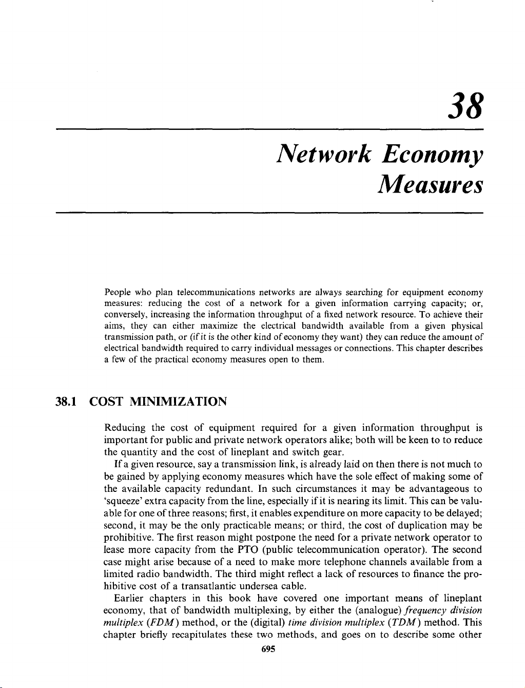
As we may recall from the example of Figure 38.1, a single four-wire circuit and a
pair of
channel translating equipments
(CTE)
enable us to derive 12 telephone channels
between the end points A and B. This compares with the
12
individually wired tele-
phone circuits which might otherwise be required.
In much the same way as zyxwvutsrqponmlkjihgfedcbaZYXWVUTSRQPONMLKJIHGFEDCBA
4
kHz bandwidths (individual telephone channels) can be
multiplexed by
CTE
to form an FDM
group,
so FDM groups can be multiplexed by
group translating equipment
(GTE)
to form
supergroups,
and
supergroups
can be formed
into
hypergroups
by STE.
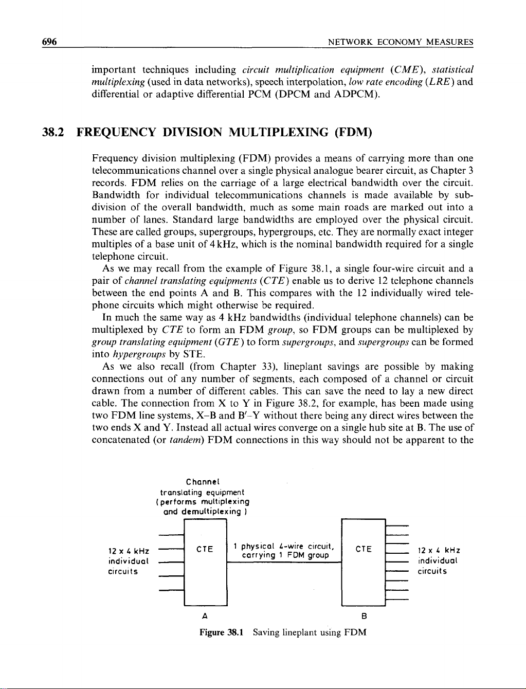
As
we also recall (from Chapter
33),
lineplant savings are possible by making
connections out of any number of segments, each composed of a channel or circuit
drawn from a number of different cables. This can save the need to lay a new direct
cable. The connection from X to
Y
in Figure 38.2, for example, has been made using
two FDM line systems, X-B and
B’-Y
without there being any direct wires between the
two ends X and
Y.
Instead all actual wires converge on a single hub site at
B.
The use of
concatenated (or
tandem)
FDM connections in this way should not be apparent to the
Channel
translating equipment
(performs multiplexing
and demultiplexing
1
-
12
X zyxwvutsrqponmlkjihgfedcbaZYXWVUTSRQPONMLKJIHGFEDCBA
L
kHz
carrying
1 zyxwvutsrqponmlkjihgfedcbaZYXWVUTSRQPONMLKJIHGFEDCBA
FDM
group
-
12
X
L
kHz
individual
-
individual
circuits
-
circuits
CTE
-
CTE zyxwvutsrqponmlkjihgfedcbaZYXWVUTSRQPONMLKJIHGFEDCBA
1
physical L-wire clrcult,
-
7
A
B
Figure
38.1
Saving lineplant using
FDM
FREQUENCY DIVISION MULTIPLEXING
(FDM) zyxwvutsrqponmlkjihgfedcbaZYXWVUTSRQPONMLKJIHGFEDCBA
697 zyxwvutsrqponmlkjihgfedcbaZYXWVUTSRQPONMLKJIHGFEDCBA
‘Satellite
site’
Other
satellite sites
X
‘Satellite
site‘
FDM
group
Y
Figure
38.2 Tandem use of
FDM
systems
end user provided the interconnections are four-wire and not two-wire, as the full
bandwidth is carried ‘transparently’ (i.e. without altering the signal significantly unlike
the methods
of
compression we shall discuss later in the chapter). There is a slight
degradation which results from the cumulative effect of repeated multiplexing and
demultiplexing,
so
that the number
of
tandem sections should be minimized.
So
though
a two-wire interconnection between tandem sections is possible, it is not recommended
because
of
the nightmare combination of circuit stability and echo problems that it
creates (see Chapter 33).
In the example shown in Figure 38.2, a connection between users
X
and
Y
passes
through tandem FDM systems A-B and B’-C. Between
A
and B it is carried as part
of
the FDM group. At B it is demultiplexed and remultiplexed (at B’) into another FDM
group B’-C. zyxwvutsrqponmlkjihgfedcbaZYXWVUTSRQPONMLKJIHGFEDCBA
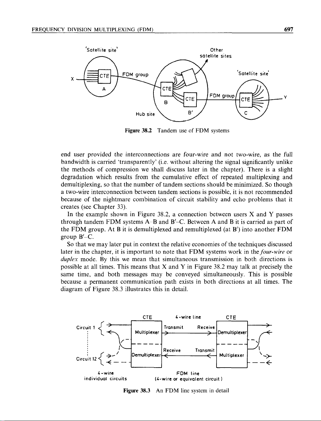
So
that we may later put in context the relative economies of the techniques discussed
later in the chapter,
it
is important to note that FDM systems work in thefour-wire or
duplex
mode. By this we mean that simultaneous transmission in both directions is
possible at all times. This means that
X
and
Y
in Figure 38.2 may talk at precisely the
same time, and both messages may be conveyed simultaneously. This is possible
because a permanent communication path exists in both directions at all times. The
diagram of Figure 38.3 illustrates this in detail.
CTE L-wire line CTE
Transmit Receive zyxwvutsrqponmlkjihgfedcbaZYXWVUTSRQPONMLKJIHGFEDCBA
\
,
;
Demultiplexer
------
Receive Transmit
Clrcuit
12
’
DemultiNexer
<
:
{:-L
<
Multiplexer
‘
-> zyxwvutsrqponmlkjihgfedcbaZYXWVUTSRQPONMLKJIHGFEDCBA
----e
L
-
wire FDM line
individual circuits (L-wire or equivalent circuit
1
Figure
38.3
An
FDM
line system
in
detail
698 zyxwvutsrqponmlkjihgfedcbaZYXWVUTSRQPONMLKJIHGFEDCBA
NETWORK ECONOMY MEASURES
Another method of obtaining even greater lineplant economy using FDM is to
allocate only
3
kHz bandwidth (as opposed to 4 kHz) for each individual speech
channel. This was the method used on early transatlantic cables. The method has fallen
out of use due to the quality impairments that results.
38.3
TIME DIVISION MULTIPLEXING
On digital lineplant the FDM technique is not normally applied. In rare cases, however,
one of two devices, either a zyxwvutsrqponmlkjihgfedcbaZYXWVUTSRQPONMLKJIHGFEDCBA
codec
(coder/decoder) or a
trans-multiplexor,
is useful as a
means of enabling an FDM group or supergroup to be carried on digital plant. The
normal multiplexing method for digital signals on digital plant is called
time division
multiplexing
(TDM), as we learned in Chapter 5.
In TDM digital line systems the lowest bit speed (corresponding to a single telephone
or data channel) is 64 kbit/s. Thus linesystems operate at bit speeds equal to, or an
integer multiple of, 64 kbit/s.
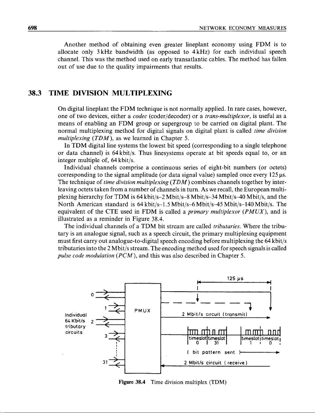
Individual channels comprise a continuous series of eight-bit numbers (or octets)
corresponding to the signal amplitude (or data signal value) sampled once every 125
PS.
The technique of
time division multiplexing
(TDM)
combines channels together by inter-
leaving octets taken from a number of channels in turn. As we recall, the European multi-
plexing hierarchy for
TDM
is
64 kbit/s-2 Mbit/s-S Mbit/s-34 Mbit/s40 Mbit/s, and the
North American standard is 64 kbit/s-1.5 Mbit/s-6 Mbit/s45 Mbit/s-140 Mbit/s. The
equivalent
of
the CTE used in FDM is called a
primary multiplexor
(PMUX),
and is
illustrated as a reminder in Figure 38.4.
The individual channels
of
a TDM bit stream are called
tributaries.
Where the tribu-
tary is an analogue signal, such as a speech circuit, the primary multiplexing equipment
must first carry out analogue-to-digital speech encoding before multiplexing the 64 kbit/s
tributaries into the 2 Mbit/s stream. The encoding method used for speech signals is called
pulse code modulation
(PCM),
and this was also described in Chapter 5. zyxwvutsrqponmlkjihgfedcbaZYXWVUTSRQPONMLKJIHGFEDCBA
Individual zyxwvutsrqponmlkjihgfedcbaZYXWVUTSRQPONMLKJIHGFEDCBA
6L
Kbitk
tributary
circuits zyxwvutsrqponmlkjihgfedcbaZYXWVUTSRQPONMLKJIHGFEDCBA
PMUX
2
Mbitls clrcuit (transmit1
I zyxwvutsrqponmlkjihgfedcbaZYXWVUTSRQPONMLKJIHGFEDCBA
rrln
m
mm
rind
timeslot timeslot timesloti timeslot
I
0
31
1101
I
(
bit pattern sent
1-=
2
Mbit/s circuit
(
receive
1
*
Figure
38.4
Time division multiplex
(TDM)
WAVELENGTH DIVISION MULTIPLEXING
699 zyxwvutsrqponmlkjihgfedcbaZYXWVUTSRQPONMLKJIHGFEDCBA
In common with FDM signals, TDM bit streams operate in a duplex mode and
require four-wire transmission. Also like FDM, individual TDM channels may be
concatenated together without significant impairment of the end-to-end signal quality,
because the zyxwvutsrqponmlkjihgfedcbaZYXWVUTSRQPONMLKJIHGFEDCBA
64
kbit/s or other bit stream is carried ‘transparently’.
38.4
WAVELENGTH DIVISION MULTIPLEXING zyxwvutsrqponmlkjihgfedcbaZYXWVUTSRQPONMLKJIHGFEDCBA
Wavelength division multiplexing (WDM)
extends still further the bit rate capacity
of
optical fibre. The technique relies on the sharing of a single fibre between a number
of
transmitting lasers of LEDs and receiving LEDs. The different transmitter/receiver pairs
(e.g. at
1300
nm and 1500 nm) are able to share the fibre harmoniously merely by working
at different light wavelengths. We discussed this technique in Chapter
8.
38.5
CIRCUIT MULTIPLICATION EQUIPMENT (CME)
Circuit multiplication equipment (CME)
is
a term used to describe various types of
equipment capable of increasing the number of data or speech circuits that may be
derived from a cable or a fixed bandwidth. The term, however, is not usually used to
describe multiplexing equipment, such as that needed for FDM or TDM.
Circuit multiplication equipments
tend to use ‘corner cutting’ methods to derive
bandwidth economy, by one of a combination of the following practices zyxwvutsrqponmlkjihgfedcbaZYXWVUTSRQPONMLKJIHGFEDCBA
0
statistical multiplexing or
interpolation
of individual channels
0
bandwidth
compression
of analogue signals, or
low
bit rate encoding
(LRE zyxwvutsrqponmlkjihgfedcbaZYXWVUTSRQPONMLKJIHGFEDCBA
-
of
PCM encoded signals)
0
data multiplexing
0
data compression
Different types of circuit multiplication equipment are available, designed either for
voice or data network use. Most voice network equipment is described simply as CME,
but devices intended for use on data networks include
statistical multiplexors, data
multiplexors
and
data compressors.
All these devices (data and voice) are similar in
purpose, the main difference between them being the compression technique used. For
example,
statistical multiplexors
employ the interpolation method of bandwidth
economy, and voice CME may employ bandwidth compression as well.
38.6 SPEECH INTERPOLATION AND STATISTICAL MULTIPLEXING
We have noted that FDM and TDM transmission systems are designed to allow
duplex
operation (simultaneous transmission of speech or data in both directions). However,
each direction
of
transmission is probably in use only about
40%
of
the time? In speech,
![Biến Tần FR-A700: Sổ Tay Hướng Dẫn Cơ Bản [Chi Tiết]](https://cdn.tailieu.vn/images/document/thumbnail/2019/20191130/cac1994/135x160/1741575103503.jpg)
![Xử lý số tín hiệu: Tài liệu thí nghiệm [Chuẩn SEO]](https://cdn.tailieu.vn/images/document/thumbnail/2018/20180821/danhvi27/135x160/7141534836177.jpg)


![Catalogue Insulators: [Thêm từ mô tả phù hợp với nội dung catalogue]](https://cdn.tailieu.vn/images/document/thumbnail/2015/20150608/sincos/135x160/6521433725774.jpg)


%20--%3e%3cdefs%3e%3cstyle%3e%20.st0%20{%20fill:%20%23fff;%20}%20.st1%20{%20fill:%20%237800fa;%20}%20%3c/style%3e%3c/defs%3e%3cpath%20class='st1'%20d='M117.78,12.18H43.11c2.9,3.47,4.65,7.94,4.65,12.82,0,5.6-2.3,10.66-6.01,14.29h76.02l7.22-13.56-7.22-13.56Z'/%3e%3cg%3e%3cpath%20class='st0'%20d='M53.58,26.17h-.59v-1.46h.59v-4.96h2.83c1.78,0,2.67.94,2.67,2.82v5.76c0,1.87-.89,2.81-2.67,2.81h-2.83v-4.96ZM55.36,21.37v3.34h1.1v1.46h-1.1v3.34h1.01c.61,0,.91-.37.91-1.1v-5.93c0-.74-.3-1.1-.91-1.1h-1.01Z'/%3e%3cpath%20class='st0'%20d='M65.99,31.14h-1.8l-.31-2.07h-2.19l-.31,2.07h-1.64l1.82-11.39h2.62l1.82,11.39ZM65.28,18.04c-.25.46-.51.77-.75.94-.21.15-.47.22-.79.22-.26,0-.57-.07-.92-.22l-.38-.15c-.14-.05-.26-.07-.37-.07-.3,0-.53.18-.71.54l-.91-.68c.25-.46.51-.77.75-.94.21-.14.48-.21.79-.21.26,0,.57.07.92.21l.38.15c.14.05.26.07.37.07.3,0,.53-.18.71-.54l.91.68ZM61.91,27.52h1.73l-.87-5.76-.87,5.76Z'/%3e%3cpath%20class='st0'%20d='M74.53,26.89v1.52c0,1.91-.89,2.86-2.67,2.86s-2.67-.95-2.67-2.86v-5.93c0-1.91.89-2.86,2.67-2.86s2.67.95,2.67,2.86v1.11h-1.69v-1.22c0-.75-.31-1.12-.93-1.12s-.93.37-.93,1.12v6.15c0,.74.31,1.11.93,1.11s.93-.37.93-1.11v-1.63h1.69Z'/%3e%3cpath%20class='st0'%20d='M81.4,31.14h-1.8l-.31-2.07h-2.19l-.31,2.07h-1.64l1.82-11.39h2.62l1.82,11.39ZM75.9,19.2l1.52-1.91h1.71l1.51,1.91h-1.61l-.76-.95-.75.95h-1.61ZM77.32,27.52h1.73l-.87-5.76-.87,5.76ZM83.1,15.99l-1.76,1.91h-1.26l1.17-1.91h1.86Z'/%3e%3cpath%20class='st0'%20d='M84.86,19.75c1.78,0,2.67.94,2.67,2.82v1.48c0,1.87-.89,2.81-2.67,2.81h-.85v4.28h-1.79v-11.39h2.64ZM84.01,21.37v3.86h.85c.58,0,.87-.36.87-1.08v-1.71c0-.71-.29-1.07-.87-1.07h-.85Z'/%3e%3cpath%20class='st0'%20d='M93.51,19.75c1.78,0,2.67.94,2.67,2.82v1.48c0,1.87-.89,2.81-2.67,2.81h-.85v4.28h-1.79v-11.39h2.64ZM92.66,21.37v3.86h.85c.58,0,.87-.36.87-1.08v-1.71c0-.71-.29-1.07-.87-1.07h-.85Z'/%3e%3cpath%20class='st0'%20d='M98.8,31.14h-1.79v-11.39h1.79v4.88h2.03v-4.88h1.83v11.39h-1.83v-4.88h-2.03v4.88Z'/%3e%3cpath%20class='st0'%20d='M105.36,24.55h2.46v1.62h-2.46v3.34h3.09v1.63h-4.88v-11.39h4.88v1.63h-3.09v3.18ZM108.17,17.29l-1.76,1.91h-1.26l1.17-1.91h1.86Z'/%3e%3cpath%20class='st0'%20d='M112.2,19.75c1.78,0,2.67.94,2.67,2.82v1.48c0,1.87-.89,2.81-2.67,2.81h-.85v4.28h-1.79v-11.39h2.64ZM111.35,21.37v3.86h.85c.58,0,.87-.36.87-1.08v-1.71c0-.71-.29-1.07-.87-1.07h-.85Z'/%3e%3c/g%3e%3ccircle%20class='st1'%20cx='25'%20cy='25'%20r='20'/%3e%3cpath%20class='st0'%20d='M32.78,19.27c2.92,0,4.43,2.55,5.28,5.33l.71,2.17c.14.38-.33.75-.71.75h-5.61c.19-.33.24-.71.09-1.08l-.75-2.45c-.43-1.32-.99-2.64-1.79-3.77.75-.57,1.65-.94,2.78-.94h0ZM25,18.38c3.25,0,4.9,2.78,5.89,5.89l.76,2.45c.14.42-.33.8-.8.8h-11.69c-.42,0-.94-.38-.8-.8l.75-2.45c.99-3.11,2.64-5.89,5.89-5.89h0ZM25,11.35c1.74,0,3.11,1.37,3.11,3.11s-1.37,3.11-3.11,3.11-3.11-1.41-3.11-3.11,1.41-3.11,3.11-3.11h0ZM17.27,19.27c1.08,0,1.98.38,2.73.94-.8,1.13-1.37,2.45-1.74,3.77l-.8,2.45c-.14.38-.05.75.09,1.08h-5.56c-.42,0-.9-.38-.75-.75l.71-2.17c.9-2.78,2.41-5.33,5.33-5.33h0ZM17.27,12.91c1.51,0,2.78,1.27,2.78,2.83s-1.27,2.83-2.78,2.83-2.83-1.27-2.83-2.83,1.27-2.83,2.83-2.83h0ZM32.78,12.91c1.56,0,2.78,1.27,2.78,2.83s-1.23,2.83-2.78,2.83-2.83-1.27-2.83-2.83,1.27-2.83,2.83-2.83h0ZM27.07,28.56v.09c0,.57-.24,1.08-.61,1.46h0v.05c-.38.33-.9.57-1.46.57s-1.08-.24-1.46-.61h0c-.38-.38-.61-.9-.61-1.46v-.09h1.41v.09c0,.19.05.38.19.47v.05c.09.09.28.19.47.19s.38-.09.47-.19v-.05c.14-.09.24-.28.24-.47t-.05-.09h1.41ZM30.99,28.56v.09c0,1.65-.66,3.16-1.74,4.24-1.08,1.08-2.59,1.79-4.24,1.79s-3.16-.71-4.24-1.79l-.05-.05c-1.04-1.08-1.7-2.55-1.7-4.2v-.09h1.41v.09c0,1.27.47,2.4,1.27,3.25h.05c.85.85,1.98,1.37,3.25,1.37s2.4-.52,3.25-1.37c.85-.8,1.37-1.98,1.37-3.25v-.09h1.37ZM34.99,28.56v.09c0,2.78-1.13,5.28-2.92,7.07-1.79,1.79-4.29,2.92-7.07,2.92s-5.23-1.13-7.07-2.92c-1.79-1.79-2.92-4.29-2.92-7.07v-.09h1.41v.09c0,2.4.94,4.53,2.5,6.08,1.56,1.56,3.72,2.5,6.08,2.5s4.52-.94,6.08-2.5c1.56-1.56,2.5-3.68,2.5-6.08v-.09h1.41Z'/%3e%3c/svg%3e)