P-ISSN 1859-3585 E-ISSN 2615-9619 https://jst-haui.vn SCIENCE - TECHNOLOGY
Vol. 61 - No. 1 (Jan 2025) HaUI Journal of Science and Technology 95
MODELING AND SIMULATING THE DYNAMICS
OF AN ADAPTIVE THROTTLE SYSTEM ON AN AUTOMOBILE
NH A VÀ PHỎNG ĐNG LỰC HỌC HTHNG GA THÍCH NG TRÊN Ô TÔ
Nguyen Xuan Tuan1,*, Luong Ngoc Huyen1
DOI: http://doi.org/10.57001/huih5804.2025.014
ABSTRACT
Currently, with the rapid development of science and technology, research
and application of information technology, electronics, and automation in
various automotive features, such as warning systems and automatic distance-
keeping with vehicles in front, automatic throttle control, have become essential
for enhancing safety and convenience for drivers. This article discusses an
adaptive cruise control system aimed at monitoring the dist
ance with the vehicle
ahead. This system allows for the automatic control of the throttle by electronic
control signals instead of manual pedal operation. In the research, a predictive
control model (MPC) is utilized within the Matlab/Simulink software to
simulate
the control process of the research model.
Keywords:
automotive dynamics, distance control, adaptive throttle
control, predictive control, Matlab/Simulink software, vehicle speed control,
automatic throttle system modeling.
TÓM TT
Hiện nay vi sự phát triển mạnh mẽ về khoa học kỹ thuật, việc nghiên cứ
u,
ứng dụng công nghệ thông tin, điện tử, tự động hóa lên một số
tính năng n
cảnh báo, hỗ trợ giữ khoảng cách với xe phía trước, điều khiển ga tự độ
bị trên các xe ô tô để ng tính an toàn, tiện nghi cho lái xe là yêu cầu cấ
p bách.
Bài báo đề cập đến hệ thống ga thích ứng nhằm kiểm soát khoảng cách v
i xe
ô chạy phía trước, hệ thống cho phép điều khiển tự động bướm ga củ
a xe
bằng tín hiệu điều khiển điện tử thay người lái tác động vào bàn đạ
p ga.
Trong nghiên cứu sử dụng hình điều khiển dự đoán
MPC (Model
Predictive Control) trong phần mềm Matlab/Simulink để mô phỏ
ng quá trình
điều khiển của mô hình nghiên cứu.
Tkhóa: Động lực học ô , kiểm soát khoảng cách, điều khiển ga thích
ng,
điều khiển dự đoán, phần mềm Matlab/Simulink, kiểm soát vận t
c ô tô, mô hình
hóa hệ thống ga tự động.
1
School of Mechanical and Automotive Engineering, Hanoi University of Industry,
Vietnam
*Email: tuannx@haui.edu.vn
Received: 06/5/2024
Revised: 29/8/2024
Accepted: 26/01/2025
1. INTRODUCTION
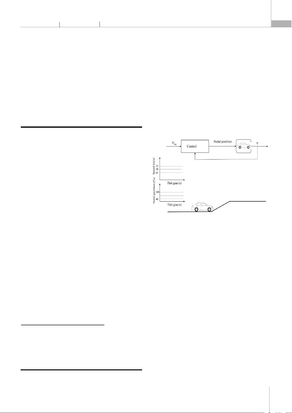
Figure 1. Diagram of the Adaptive Throttle System Operation
Currently, with the strong development of science and
technology, the research and application of information
technology, electronics and automation on car safety
systems such as: Electronic Throttle Control (ETC) allows
automatic control of the vehicle's throttle by electronic
control signals instead of the driver acting on the pedal
railway station; The Traction Control System (TCS) uses
sensors to monitor traction status and adjusts the throttle
and brake system to prevent wheels from sliding;
Electronic Stability Control (ESC) reduces the risk of
derailment and loss of control by automatically
intervening on the brakes and throttle to maintain vehicle
stability in dangerous situations (such as slipping or
tipping); Adaptive Cruise Control allows the driver to set a
sustained speed on a highway or highway; Collision
Warning System Using sensors and radar, this system can
detect potential incidents and warn drivers through audio
or visual to help drivers react in time; Lane Keeping Assist
monitors the vehicle's position in the lane and provides
warning or intervention to keep the vehicle in the middle
of the lane, preventing misdirection; The Distance Warning
CÔNG NGHỆ https://jst-haui.vn
Tạp chí Khoa học và Công nghệ Trường Đại học Công nghiệp Hà Nội Tập 61 - Số 1 (01/2025)
96
KHOA H
ỌC
P
-
ISSN 1859
-
3585
E
-
ISSN 2615
-
961
9
system monitors the distance between your vehicle and
the vehicle in front and warns you if you are too close or at
risk of a collision. For the purposes of the study, the paper
refers to the distance control system between an adaptive
throttle car and a front car, which allows automatic control
of the vehicle's throttle by means of an electronic control
signal instead of the driver acting on the accelerator pedal
(Fig. 1): The sensor/radar on the research vehicle will
recognize the distance to the vehicle ahead to decide
whether to accelerate or decelerate, thereby controlling
the corresponding position of the accelerator pedal
(electronic throttle system).
2. BUILDING DYNAMICS MODELS
The math model describes the interaction between an
adaptive throttle car and a vehicle ahead to maintain a
safe distance. In this study, a vehicle equipped with
adaptive throttle (adaptive vehicle), a system that uses
sensors/radar, measures the distance to the vehicle ahead
of it running in the same lane (Dđo), sensors/radar and
measures the relative velocity of the vehicle ahead (Vđo),
at which point the control system decides which mode to
use based on sensor/radar measurements according to
The specic real-time is as follows (Fig. 2):
- Mode 1 (speed control): The vehicle with adaptive
throttle has a speed lower than the vehicle in front, at
which point the system will control the adaptive throttle
vehicle to accelerate to the set speed by controlling the
increase in throttle opening.
- Mode 2 (distance control): The vehicle with adaptive
throttle has a speed greater than the vehicle in front, at
which point the system will control a safe distance from
the vehicle ahead
Figure 2. Diagram showing the control mode of vehicles tted with
adaptive throttle system
Thus, the adaptive throttle system is responsible for
making the car with adaptive throttle able to move at the
speed set by the driver, while maintaining a safe distance
from the vehicle ahead. The differential equation of
motion of the system is formulated as follows [1]:
Motion differential equation for the vehicle ahead:

+
, + v = v (1)

+x = x (2)
Motion differential equations for adaptive throttle
vehicles:

+
, + v = v (3)

+x = x (4)
The relationship equation between the adaptive
throttle vehicle and the vehicle in front by the distance of
the two vehicles [2]:
d = (v v)dt

 (5)
Where:
X0T: initial position of the car in front;
V0t: initial set velocity of the vehicle ahead;
vt: variable velocity of the vehicle ahead;
xT: initial location of the vehicle with adaptive throttle;
At: variable acceleration of the vehicle ahead;
V0tu: initial set velocity of the adaptive throttle vehicle;
vtu: variable velocity of the vehicle on the adaptive
throttle mounting side;
Atu: variable acceleration of the vehicle on the
adaptive throttle mounting side.
3. CONTROLLER FOR MODEL
The paper uses MPC, which uses a model to predict
the response of an adaptive throttle vehicle at times to
the vehicle ahead within a certain forecast range. Based
on this forecast response, an optimization algorithm is
used to calculate the sequence of future control signals
within the control range so that the deviation between
the forecast by the model and the given standard signal
is minimal. The MPC control method is a method of
designing controllers in the time domain so that it can be
applied to linear as well as non-linear systems [3, 4].
Objectives to control the operating mode of the
adaptive throttle system:
P-ISSN 1859-3585 E-ISSN 2615-9619 https://jst-haui.vn SCIENCE - TECHNOLOGY
Vol. 61 - No. 1 (Jan 2025) HaUI Journal of Science and Technology 97
- If the measured distance (by sensor/radar): DđoDat:
safe distance, the velocity control mode works. The
control objective is to follow the speed set by the driver.
- If Dđo < Dat then the distance control mode works.
The control objective is to maintain a safe distance.
The control block diagram is represented as Fig. 3.
Figure 3. Adaptive throttle control block diagram
Steps to solve the problem of binding forecast control
[5]:
At the time ki already has the value x(ki),U(ki)
Step 1: Calculate x(ki+1):
x(ki+1)= Ax(k)+BU(k)
=> x(ki+1)= x(ki+1)x(ki)
And: y(ki+1)= Cx(k+1)
x(ki+1)=∆x(ki+1)
Y(ki+1)
Step 2: Dene values
γ = UmaxU(ki)
Umin+U(ki), M= 1 00
−1 00
Calculate the minimum value of the target function.
γ = (RY)(RY)+∆UR
∆U
With binding conditions:
M∆U γ
Determine the control value variation ∆U(ki+1) is
the rst component of the U.
Hence the control signal at the step ki+1
u(ki+1)= u(ki) + ∆u(ki+1)
So here we have the control state values at the time
of sampling ki+1:
x(ki+1), u(ki+1)
Repeat step 1 until ∆U = 0.
4. SIMULATE THE OPERATION OF THE MODEL
Use Matlab/Simulink software with MPC controller to
simulate system operation. Choosing to simulate a car
running on the highway, the acceleration of the vehicle in
front changes in a sinusoidal shape during simulation, the
output of the adaptive throttle control unit is the
acceleration signal of the car with adaptive throttle.
Based on the minimum safe speed and distance
regulations [6], the selection of simulation conditions
parameters is as follows: Initial position of the vehicle
ahead: x0_pt = 100 (m); Initial speed of the vehicle ahead:
v0_pt = 28 (m/s); The initial position of the vehicle with
adaptive throttle: x0_tu = 0 (m); Initial speed of the vehicle
with adaptive throttle: v0_tu = 16.8 (m/s).
Input parameters for the simulation model: Set speed
(Vdat), The set is changed to simulate for two cases: Control
the speed of the vehicle with the throttle adaptively to
the set speed when the vehicle velocity in front is greater
than the set speed, and Control the speed of the vehicle
with the throttle adaptively to ensure a safe distance
when the vehicle speed in front is small than set velocity.
The output parameter of the model is the acceleration of
the adaptive throttle vehicle.
Simulation results:
- Where Vdat = 22.4 (m/s) controls the set velocity,
shown in Fig. 4: The acceleration of the throttle vehicle is
then gradually reduced and by the 5th second the
acceleration is zero; correspondingly, the speed of the
throttle vehicle prefers to increase to the set velocity (5th
second), it remains the same; Because the set speed of the
adaptive throttle vehicle is smaller than the vehicle speed
ahead, the distance between the two vehicles increases
compared to the safe distance.
Figure 4. Acceleration representation of adaptive throttle vehicle and
vehicle ahead when Vdat = 22.4 (m/s)
CÔNG NGHỆ https://jst-haui.vn
Tạp chí Khoa học và Công nghệ Trường Đại học Công nghiệp Hà Nội Tập 61 - Số 1 (01/2025)
98
KHOA H
ỌC
P
-
ISSN 1859
-
3585
E
-
ISSN 2615
-
961
9
- Where Vdat = 33.6 (m/s) controls to maintain a safe
distance, shown in Fig. 5: The acceleration of the vehicle
with positive throttle then decreases and by the 10th
second the acceleration is zero then from the 45th second
the acceleration follows the vehicle ahead;
correspondingly, the speed of the throttle vehicle prefers
to increase to the set velocity (10th second) and from the
45th second the control follows the vehicle velocity
ahead; Since the set speed of the adaptive throttle vehicle
is greater than the vehicle speed in front, the distance
between the two vehicles gradually decreases and by the
45th second begins to control the distance to maintain a
safe distance.
Figure 5. Acceleration representation of adaptive throttle vehicle and front
vehicle when Vdat = 33.6 (m/s)
5. CONCLUSIONS
The article models and simulates the adaptive throttle
system installed in a car, simulated by Matlab/Simulink
software in 2 modes: Speed control when the speed of
the vehicle tted with the adaptive throttle system is less
than the speed of the vehicle in front and the set speed;
Distance control when the speed of the adaptive throttle
vehicle is greater than the speed of the vehicle in front
and the distance to the vehicle in front is less than the safe
distance. The simulation results show the effectiveness
and reliability of the research model. The controller
ensures that the actual distance between the two
vehicles is greater than the set safe distance. When the
actual distance is large enough, then the controller
ensures that the vehicle with the accelerator adapts to the
speed set by the driver.
REFERENCES
[1]. Matlab Toolbox, How to design an MPC Controler with Simulink and and
Model Predictive Control tool boox. 2018.
[2]. Payman Shakouri, Andrzej Ordys, Gordana Collier, “Teaching Model
Predictive Control Algorithm Using Starter Kit Robot, Engineering Education, 8,
2, 2013. doi: 10.11120/ened.2013.00018.
[3]. Maciejowski J. M., Predictive Control with Constraints. Prentice Hall,
Upper Saddle River, NJ, 2002.
[4]. McIntosh A. R., W. M. Canney, The Dirty Secrets of Model Predictive
Controller Sustained Value, in Proc. Internat. Sympos. On Advanced Control of
Industrial Processes (ADCONIP 2008), Paper MoB1.4, Jasper, Alberta, Canada,
2008.
[5]. Trần Thái Anh Âu, Trương Thị Bích Thanh, “Ứng dụng MPC trong hệ
thống điều khiển nhiệt độ, Tạp chí Khoa học Công nghệ, Đại học Đà Nẵng,
11(108),1, 2016.
[6]. Bộ Giao Thông vận tải, Thông tư số 31/2019/TT-BGTVT quy định về tốc
độ khoảng cách an toàn của xe giới, xe máy chuyên dùng tham gia giao
thông đường bộ. Hà Nội, 2019.
THÔNG TIN TÁC GIẢ
Nguyễn Xuân Tuấn, Lương Ngọc Huyên
Trường Cơ khí - Ô tô, Trường Đại học Công nghiệp Hà Nội