
http://www.iaeme.com/IJMET/index.asp 1 editor@iaeme.com
International Journal of Mechanical Engineering and Technology (IJMET)
Volume 10, Issue 04, April 2019, pp. 1-8. Article ID: IJMET_10_04_001
Available online at http://www.iaeme.com/ijmet/issues.asp?JType=IJMET&VType=10&IType=4
ISSN Print: 0976-6340 and ISSN Online: 0976-6359
© IAEME Publication Scopus Indexed
NUMERICAL STUDY OF THE FLOW OVER
SYMMETRICAL AIRFOILS WITH GROUND
EFFECTS
Aslam Abdullah, Surendran Suresh, Siti Juita Mastura Mohd Saleh, Mohd Fadhli
Zulkafli and Mohammad Fahmi Abdul Ghafir
Department of Aeronautical Engineering, Faculty of Mechanical and Manufacturing
Engineering,
Universiti Tun Hussein Onn Malaysia, Parit Raja, Batu Pahat, Johor, Malaysia
ABSTRACT
The paper presents the ground effects on the flow over five NACA symmetrical
airfoils by analyzing the coefficients of lift. The unbounded flow over a selected airfoil
was first simulated, and the results were validated against the established data in order
to validate the method used in obtaining the lift coefficients. In the presence of ground,
we kept the angle of attack to be constantly zero throughout the computations. Ground
clearances were set based on those for aircrafts whose wing cross sections are the
airfoils of interest. ANSYS was used for such numerical computations. We illustrate
percentage increment of lift that is inversely proportional to the ground clearance. This
work sheds insight on the important parameters that need to be taken into account in
the operational of an aircraft.
Keywords: Aerodynamics, ground clearance, ground effects, lift coefficient,
symmetrical airfoils
Cite this Article Aslam Abdullah, Surendran Suresh, Siti Juita Mastura Mohd Saleh,
Mohd Fadhli Zulkafli and Mohammad Fahmi Abdul Ghafir, Numerical Study of the
Flow Over Symmetrical Airfoils with Ground Effects, International Journal of
Mechanical Engineering and Technology, 10(4), 2019, pp. 1-8.
http://www.iaeme.com/IJMET/issues.asp?JType=IJMET&VType=10&IType=4
1. INTRODUCTION
The phenomenon of ground effects becomes apparent in the proximity of solid surface, and is
beneficial in the control of normal fixed wing aircrafts during take-off and landing, and of wing-
in-ground (WIG) craft during all flight phases. When an aircraft is flown at approximately one
wing span above the runway, the interaction between the airflow around the airfoil and the
ground surface modifies the fluid velocity’s vertical component. In particular, the flow field
structure consisting of the trailing vortices is partially blocked by the ground which in turn
decreases the amount of downwash generated by the wing. [1-3].
Numerical Study of the Flow Over Symmetrical Airfoils with Ground Effects
http://www.iaeme.com/IJMET/index.asp 2 editor@iaeme.com
The airfoils of interest form the cross sections of reference aircrafts’ wings as shown in
Table-1. The specifications of the individual aircraft can be found in [4-8].
Table-1. Airfoils of interest and their corresponding military aircrafts.
Airfoil series
Aircraft
NACA 0003
F-4 Phantom II
NACA 0010
Curtiss
NACA 0012
S-3 Viking
NACA 0018
Bell P-39 Airacobra
NACA 0019
Blackburn Firebrand
Aerodynamic characteristics of the flow over the airfoils in Table-1 in the presence of
ground are numerically investigated by solving the compressible 2D Reynolds Averaged
Navier-Stokes (RANS) Equations and Spalart-Allmaras turbulence model using ANSYS. Such
flows are simulated for different chosen ground clearances and fixed angle of attack. The
influence of ground is investigated based on the lift coefficient profiles.
2. GEOMETRY, GRID AND COMPUTATIONAL DOMAIN
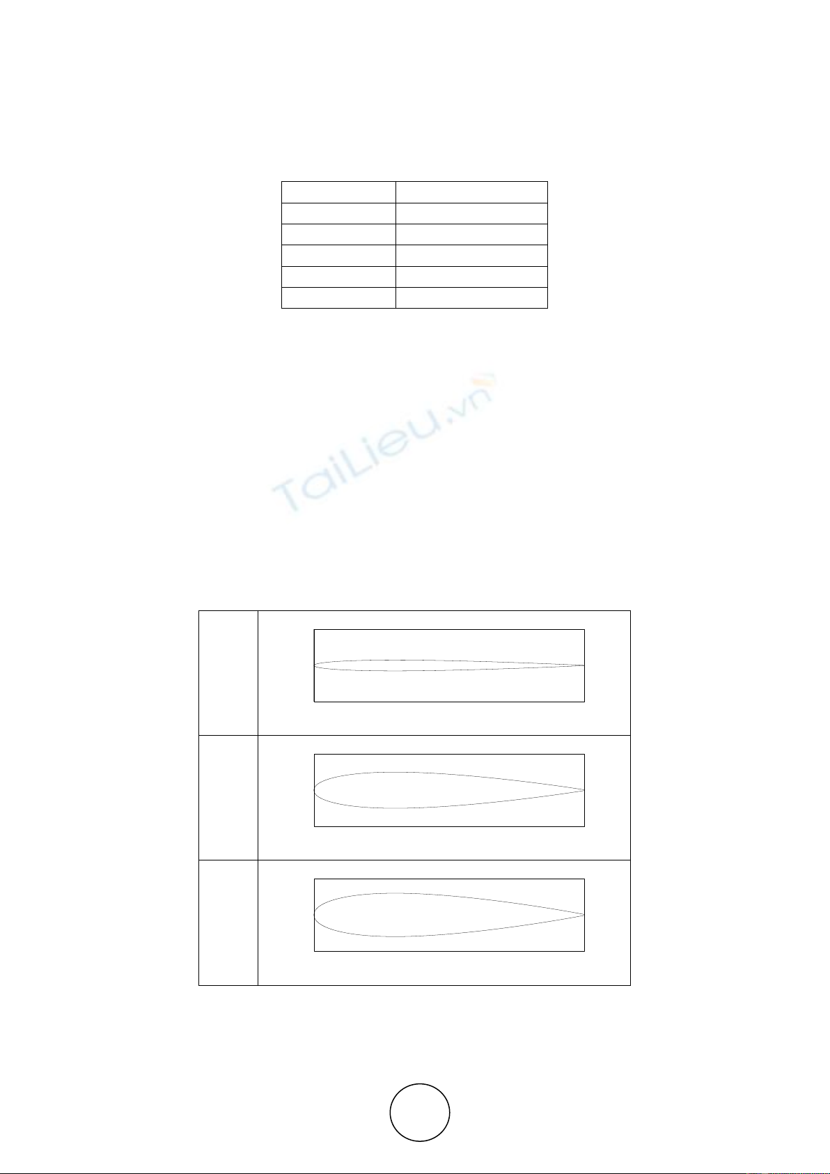
The geometries are shown in Fig-1. The only geometrical difference between these airfoils is
their thickness. The chord length of each airfoil is normalized. The geometries of interest are
relatively simple in comparison to, for instance, multi-element airfoils [9-10].
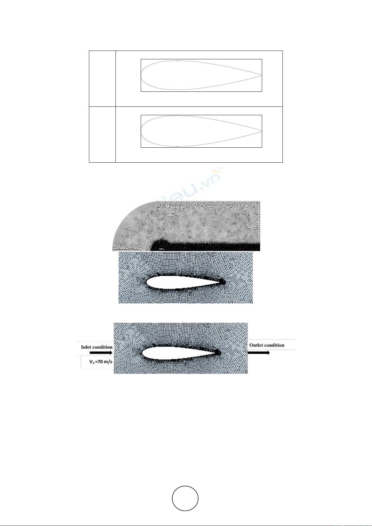
Meshes in computational domain is shown in Fig-2. Ground clearance is defined by the
ratio of distance from ground to trailing edge of airfoil h to chord length c. Inlet and outlet
boundary conditions were specified on the outer sides of computational domain (see Fig-3).
The no-slip boundary condition on the airfoil was enforced in order to produce better
representation of the reversing flow assumption [11].
(a)
(b)
(c)
-.1
.0
.1
.0 .2 .4 .6 .8 1.0
-.1
.0
.1
.0 .2 .4 .6 .8 1.0
-.1
.0
.1
.0 .2 .4 .6 .8 1.0
Aslam Abdullah, Surendran Suresh, Siti Juita Mastura Mohd Saleh, Mohd Fadhli Zulkafli and
Mohammad Fahmi Abdul Ghafir
http://www.iaeme.com/IJMET/index.asp 3 editor@iaeme.com
(d)
(e)
Figure-1. Geometries (a) NACA 0003, (b) NACA 0010, (c) NACA 0012, (d) NACA 0018 (e) NACA
0019
Figure-2. Meshing in the presence of ground
Figure-3. Airfoil moving close to the ground surface
3. METHOD VALIDATION
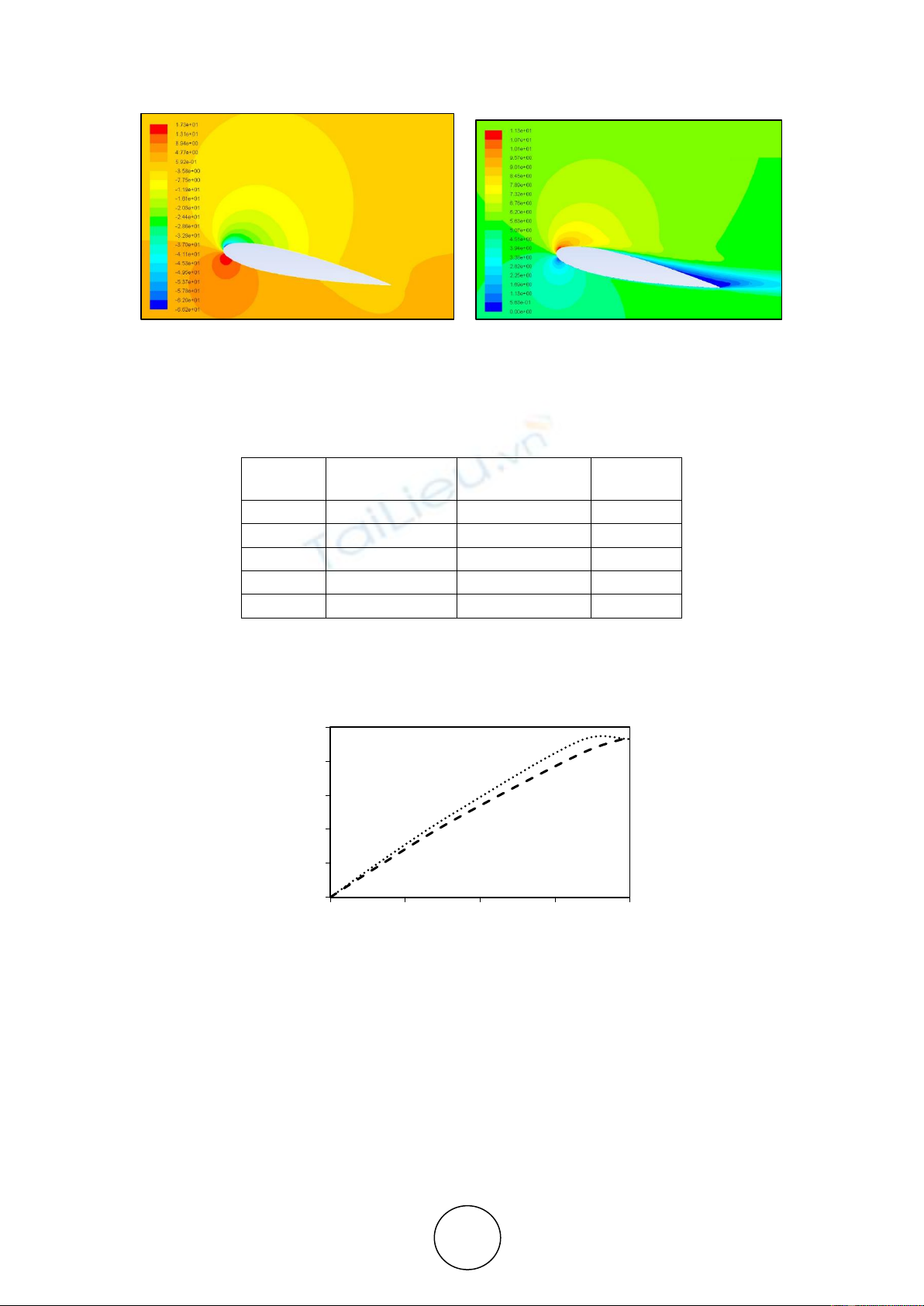
In order to validate the accuracy of the numerical experiment method, the aerodynamic
characteristics of NACA 0015 in unbounded flow were calculated. Velocity field around
NACA 0015 airfoil at stall angle of attack αstall is shown in Fig-4. Note that the airfoil is in
unbounded flow. The results in Table-2 show good agreement with the established simulation
data [12] used as reference, where the error is below 10%.
-.1
.0
.1
.0 .2 .4 .6 .8 1.0
-.1
.0
.1
.0 .2 .4 .6 .8 1.0
Numerical Study of the Flow Over Symmetrical Airfoils with Ground Effects
http://www.iaeme.com/IJMET/index.asp 4 editor@iaeme.com
Figure-4. Contours of pressure (top figure) and velocity (bottom figure) in unbounded flow passing
the airfoil of reference. Note that the stagnation point is at the pressure side of the airfoil.
Table-2. Reference and calculated values of lift coefficient and corresponding error at different angles
of attack.
α
Reference
values
Calculated
values
|Error| (%)
0o
0
0
0
2o
0.21
0.19047
9
5o
0.50
0.45904
8
10o
0.92
0.84213
8
12o (αstall)
0.93
0.94303
1
The Cl profile obtained from both the simulation in this study and the reference [12] is
presented in Figure-5. In general, the deviation increases with respect to α. Since the maximum
error is small (i.e. less than 10%), the method is used to obtain the results for all the airfoils in
Fig-1.
Figure-5. Graph of lift coefficient Cl vs angle of attack α. numerical calculation. Reference value
4. DETERMINATION OF GROUND DISTANCE
Based on the specifications of aircrafts in Table-1 whose wings’ cross sections are made of the
airfoils of interest, we list the individual average ground clerance (h/c)av as given in Table-3.
These values are based on the actual airfoil dimension and the height of the trailing edge from
the runway surface when the aircraft touches down or it is about to take-off. The vertical size
of of the undercarriage which includes the wheels is thus one of main factors in the
determination of the height. Based on (h/c)av in Table-3, we set the standard h/c = 1.5, 2.0, 2.5,
3.0.
0
0.2
0.4
0.6
0.8
1
0 3 6 9 12
Cl
α
Aslam Abdullah, Surendran Suresh, Siti Juita Mastura Mohd Saleh, Mohd Fadhli Zulkafli and
Mohammad Fahmi Abdul Ghafir
http://www.iaeme.com/IJMET/index.asp 5 editor@iaeme.com
Table-3. Ground clearance.
Airfoils
Chord length, m
(h/c)av
NACA 0003
1.94
1.72
NACA 0010
2.32
2.79
NACA 0012
2.43
3.40
NACA 0018
1.91
3.05
NACA 0019
2.28
3.71
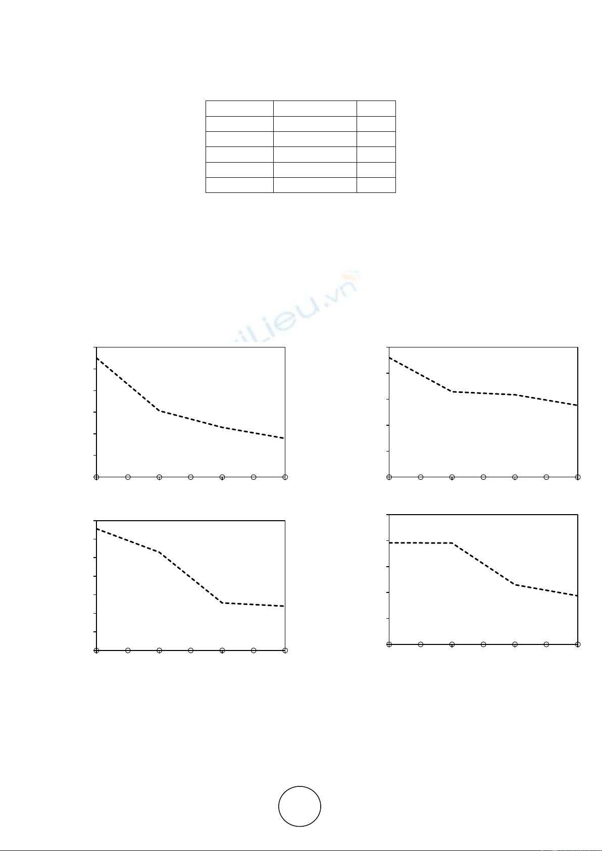
5. RESULTS OF CALCULATION
The airfoils are in ground proximity at zero angle of attack (i.e. α = 0). It is known that the
velocity is relatively low in particular at the pressure side when the airfoil approaches the
ground. This is explained by the airfoils being floated on a cushion of high-pressure air region
above the ground surface. Furthermore, the stagnation point are located to the lower side of the
symmetrical airfoils due to the ground effect. The presence of ground effects are determined by
changes in the value of lift coefficients shown in Fig-6.
(a)
(b)
(c)
(d)
.0
1.0
2.0
3.0
4.0
5.0
6.0
1.5 2 2.5 3
Cl(x 10-4)
h/c
.0
.4
.8
1.2
1.6
2.0
1.5 2 2.5 3
Cl(x 10-4)
h/c
.0
.5
1.0
1.5
2.0
2.5
3.0
3.5
1.5 2 2.5 3
Cl(x 10-4)
h/c
.0
1.0
2.0
3.0
4.0
5.0
1.5 2 2.5 3
Cl(x 10-4)
h/c


![Bài giảng Cảm biến và ứng dụng: Chương 1 - Các khái niệm và đặc trưng cơ bản [Chuẩn SEO]](https://cdn.tailieu.vn/images/document/thumbnail/2025/20251204/kimphuong1001/135x160/51101764832169.jpg)