
ISSN 1859-1531 - THE UNIVERSITY OF DANANG - JOURNAL OF SCIENCE AND TECHNOLOGY, VOL. 22, NO. 11B, 2024 77
IMPACT OF STEEL-CONCRETE SLIPPAGE ON CFST COLUMN LOAD
CAPACITY UNDER COMPLEX LOADING CONDITIONS
Pham My1*, Dinh Ngoc Hieu1,2, Le Khanh Toan1, Dang Cong Thuat1
1The University of Danang - University of Science and Technology, Vietnam
2School of Architecture, Soongsil University, South Korea
*Corresponding author: pmy@dut.udn.vn
(Received: September 26, 2024; Revised: October 11, 2024; Accepted: October 12, 2024)
DOI: 10.31130/ud-jst.2024.524E
Abstract - Concrete-Filled Steel Tubular (CFST) columns are
composite structures consisting of a steel tube and a concrete core,
offering high load-bearing capacity, especially under complex
loading conditions. When CFST columns are subjected to
simultaneous compression, bending and torsion, the interaction
between the concrete core and the steel tube plays a crucial role in the
distribution of stress and deformation. A key factor that needs to be
assessed is the relative slippage between the steel tube and the
concrete core, as it directly impacts the load-bearing capacity and
stability of the column. This study shows that when
compression/bending and torsion are applied simultaneously, the
bond between the concrete core and steel tube may weaken, leading
to slippage, which in turn reduces the structural system’s load-bearing
efficiency. Understanding and accurately assessing the impact of this
slippage is essential for improving design, ensuring CFST columns
achieve optimal load-bearing performance in practice.
Key words - CFST; Combined compression-bending-torsion
load; Torsional bearing capacity; Compressive torsional capacity;
Numerical analysis.
1. Introduction
CFST columns are widely recognized for their superior
load-bearing capacity and structural efficiency, combining
the strength of steel with the compressive capacity of
concrete. These columns are extensively used in high-rise,
industrial buildings, industrial buildings, bridges, offshore
structures, and other applications subjected to complex
loading conditions [1-6]. Many previous studies have
focused on the behavior of CFST columns under pure
compression [7-9] and combined compression and bending
[10-13]. However, in practice, one of the critical scenarios
in structural engineering is the simultaneous application of
torsion and compression [2-6, 14], which poses significant
challenges to the performance of CFST columns.
In CFST columns under combined torsion and
compression, the steel tube and concrete core interact
crucially, affecting load distribution and failure
mechanisms. The tube confines the concrete, boosting its
strength, while the concrete prevents tube buckling.
However, combined loads, particularly torsion, complicate
this interaction, causing potential slippage between the
tube and core, which reduces stiffness and load capacity.
Understanding CFST columns under simultaneous
torsion and compression is crucial for enhancing design
methods and ensuring structural safety. This paper explores
how these loading conditions affect CFST columns,
focusing on steel-concrete interaction, slippage, and its
impact on overall performance using numerical methods.
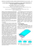
2. Problem statement
A finite element analysis model examines the impact of
relative slippage between the steel tube and concrete core
on CFST columns’ load-bearing capacity, comparing
circular (Ci) and square (Sq) cross-sections as shown in
Table 1 and Table 2. The analysis reveals how different
slippage characteristics influence their ability to resist
combined torsion, compression, and bending, helping
assess the impact of slippage on CFST structures’ load-
bearing capacity.
The paper also includes parameter studies to determine
critical torsional strength and moment for torsion-
deformation curves in composite cross-sections. These
results will support the development of theoretical models
and improvements in design methods, enhancing safety
and reliability for CFST structures under complex load
combinations like compression-torsion, bending-torsion,
and compression-bending-torsion.
3. Numerical model
3.1. Geometric and mechanical properties
The paper focuses on parameter studies by
investigating changes in the geometry of the structural
elements, variations in the material strength of the steel
tube and concrete core, the ratio of compressive force to
critical compressive force, or the ratio of bending moment
to torsional moment, etc. Detailed information on the
survey samples in the case of columns under combined
compression and torsion is provided in Table 1, where
𝑛 represents the level of axial force influence in the column
and is defined as 𝑛 = 𝑁𝑘𝑁𝑢
⁄, with 𝑁𝑘 being the axial force
applied to the column at the time of the survey, and
𝑁𝑢 being the critical axial compressive force that the
column can withstand.
In the case of CFST columns subjected to combined
bending and torsion, the relative slippage between the steel
tube and the concrete core is also predicted through finite
element analysis. The evaluation results are compared
between 9 simulations for circular cross-sections and
9 simulations for square cross-sections. Detailed
information on the survey model for columns under
combined bending and torsion is provided in Table 2,
where 𝑚0= 𝑀 𝑇
⁄ is the ratio of the bending moment to the
torsional moment during the loading process.
In the case of CFST columns subjected to combined
bending, compression, and torsion, this study only
78 Pham My, Dinh Ngoc Hieu, Le Khanh Toan, Dang Cong Thuat
investigates the simplest scenario where the compressive
force varies from 𝑁𝑘=10𝑘𝑁 to 𝑁𝑘=60𝑘𝑁, with each
step increasing by 10𝑘𝑁 and an eccentricity of
𝑒 = 300𝑚𝑚. Meanwhile, the geometric and material
parameters remain as specified in Table 1. The
investigation of relative slippage between the steel tube and
the concrete core is still based on a comparative evaluation
of circular and rectangular cross-sections, as in the
previous two cases. This allows identification of which
combined loading conditions pose the greatest risk to the
structural elements.
Table 1. Geometric and mechanical properties of survey
samples for circular and square cross-sections under combined
torsion and compression
No
Mark
Sample
demensions
Yield
strength
of steel
tube
Comp.
strength
of
concrete
core
Compressiv
e force/
critical
compressive
force ratio
-
-
D× 𝑡 × 𝑙
𝑓
𝑦
𝑓
𝑐
𝑛 = 𝑁𝑘𝑁𝑢
⁄
-
-
[𝑚𝑚]
[MPa]
[MPa]
-
1
CFT-Ci/Sq-Nk-1
138 ×4.5×450
324.34
30.4
0÷ 0.9
2
CFT-Ci/Sq-Nk-2
125 ×3.3×450
324.34
30.4
0÷ 0.9
3
CFT-Ci/Sq-Nk-3
125 ×4.5×2000
324.34
30.4
0÷ 0.9
4
CFT-Ci/Sq-Nk-4
138×3×2000
280
21.9
0÷ 0.9
5
CFT-Ci/Sq-Nk-5
114×4.5×387
280
21.9
0÷ 0.9
6
CFT-Ci/Sq-Nk-6
114×4.5×800
280
21.9
0÷ 0.9
7
CFT-Ci/Sq-Nk-7
139.8×3.5×2000
348.2
38.2
0÷ 0.9
8
CFT-Ci/Sq-Nk-8
139.8×4×2000
348.2
38.2
0÷ 0.9
9
CFT-Ci/Sq-Nk-9
139.8×4.5×2000
348.2
38.2
0÷ 0.9
Table 2. Geometric and mechanical properties of survey
samples for circular and square cross-sections under combined
torsion and bending
No
Mark
Sample
dimensions
Yield
strength
of steel
tube
Comp.
strength
of
concrete
core
Bending
moment/
torsion
moment
ratio
-
-
D× 𝑡 × 𝑙
𝑓
𝑦
𝑓
𝑐
𝑚𝑜= 𝑀 𝑇
⁄
-
-
[𝑚𝑚]
[MPa]
[MPa]
-
1
CFT-Ci/Sq-Uk-1
138 ×4.5×450
324.34
30.4
0÷ 2.4
2
CFT-Ci/Sq- Uk -2
125 ×3.3×450
324.34
30.4
0÷ 2.4
3
CFT-Ci/Sq- Uk -3
125 ×4.5×2000
324.34
30.4
0÷ 2.4
4
CFT-Ci/Sq- Uk -4
138×3×2000
280
21.9
0÷ 2.4
5
CFT-Ci/Sq- Uk -5
114×4.5×387
280
21.9
0÷ 2.4
6
CFT-Ci/Sq- Uk -6
114×4.5×800
280
21.9
0÷ 2.4
7
CFT-Ci/Sq- Uk -7
139.8×3.5×2000
348.2
38.2
0÷ 2.4
8
CFT-Ci/Sq- Uk -8
139.8×4×2000
348.2
38.2
0÷ 2.4
9
CFT-Ci/Sq- Uk -9
139.8×4.5×2000
348.2
38.2
0÷ 2.4
3.2. Material models
3.2.1. Concrete
The Concrete Plastic Damage (CPD) model in ABAQUS
simulates the behavior of concrete in CFST structures,
predicting both tensile and compressive responses under
confined lateral pressure [15, 16]. The yield function is based
on effective hydrostatic pressure and equivalent Mises stress,
influenced by integrated plastic strain rates for compression
and tension. Users can adjust the plastic yield surface using
𝐾𝑐 and 𝜎𝑏0 𝜎𝑐0
⁄, which controls the shape of the deviatoric
plane and the yield/compression stress ratio. A non-
associated flow rule governs plastic strain increments, with
the yield potential defined by the Drucker-Prager function. In
this study, the concrete dilation angle is set between 150 and
180, with damage characterized by stiffness reduction upon
unloading. Static loading allows for damage effects to be
ignored. Numerical complexities are stabilized using a
viscoplastic law, which aids convergence by introducing a
small viscosity parameter. The uniaxial compressive stress-
strain curve [17] is derived from standard tests, assuming a
perfectly plastic curve post-peak stress. The tensile stiffness
model addresses cracking, assuming stress reduction to zero
upon crack formation. Tensile strength 𝑓
𝑐𝑡 follows DIN-
1045-1 standards, with Poisson’s ratio at 0.2 and the modulus
of elasticity from Table 1 and Table 2.
3.2.2. Steel
An elastic-plastic model with the von Mises yield
criterion is used to describe the material behavior of the steel
tube. The stress-strain relationship obtained from uniaxial
tensile tests has been applied to the steel material model [17].
The Poisson’s ratio is set at 0.3, and the material properties
of the steel are taken from Table 1 and Table 2.
3.3. Mesh generation
After defining the geometry and material properties, the
concrete core is meshed using 8-node 3D-stress C3D8R
elements, which feature reduced integration with a single
integration point. This is also suitable for the steel tube
with a relatively large thickness (see Table 1 and Table 2),
as these elements provide accurate stress-strain
relationships and physical behavior modeling. Further,
C3D8R elements use reduced integration to address shear
locking issues and maintain high accuracy at integration
points located at the element center. This approach requires
smaller elements to capture stress concentrations at corners
and edges effectively.
Reduced integration elements can exhibit hourglassing
modes, but these are rare and do not typically affect well-
defined meshes. When hourglassing does occur, it can
impede convergence, but a properly generated mesh can
mitigate this issue. These elements are preferred for
complex stress states due to their reduced susceptibility to
shear locking.
For shoulder column applications, absolute rigid
elements are used. These elements are defined by a
reference node, with their shape determined by rotating or
translating a 2D profile or generating a mesh. Although the
shape remains constant, the solid can move significantly.
The mass and inertia are either calculated from the element
distribution or assigned directly.
Motion for absolute rigid solids is controlled by
boundary conditions on the reference node. Loads can be
applied as concentrated or distributed loads on nodes or
elements, or directly on the reference node. Absolute solids
interact with the model through connections to deformation
elements and contact with them.
3.4. Boundary conditions
The steel tube and concrete core at the base are fixed to
a rigid steel plate controlled by a reference node. The
ISSN 1859-1531 - THE UNIVERSITY OF DANANG - JOURNAL OF SCIENCE AND TECHNOLOGY, VOL. 22, NO. 11B, 2024 79
column is treated as having a fixed base, with the node
constrained in all six displacement degrees of freedom. The
study focuses on the column's critical behavior, applying a
static load with displacement control at the top.
4. Results and discussion
4.1. Investigation of CFST columns subjected to
simultaneous bending, compression and torsion
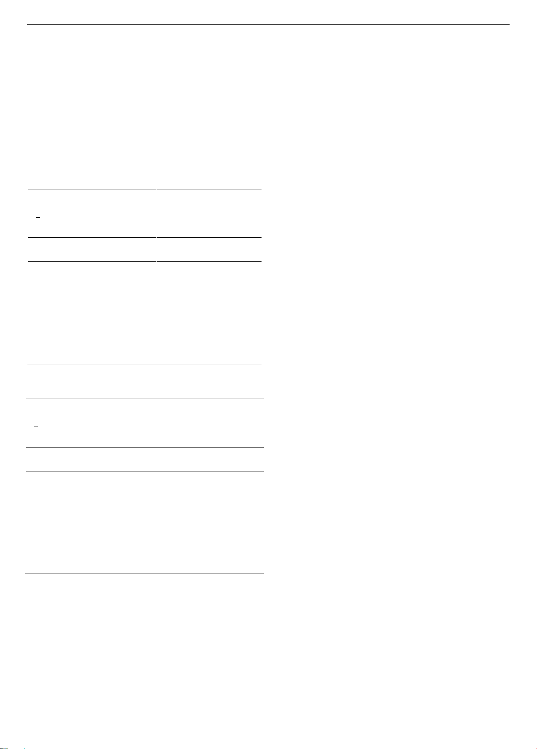
First, the paper focuses on discussing the typical curve
of the torsional moment (resulting in shear stress) versus the
angle of twist, as analyzed and calculated in Figure 1.
Generally, the results show that to analyze the physical
behavior of CFST columns under simultaneous compression
and torsion, we can divide the relationship between the
torsional moment and the angle of twist into three stages.
The first stage, OA, from the origin O to point A, is
linear, indicating an elastic phase. Here, steel and concrete
interact, with forces on the steel tube being transferred to
the concrete core. At point A, slippage between the steel
tube and concrete core begins, and steel yielding starts.
In the second stage, from point A to point B, the curve
transitions from a straight line (OA) to a nonlinear curve
(AB). Simulations reveal slippage between the concrete core
and steel tube, indicating nonlinear elastic-plastic behavior.
During this phase, increasing torque causes concrete
cracking and lateral expansion. The steel tube restricts this
expansion, with resistance growing due to friction as torsion
increases. This continues until reaching point B.
In the third stage, shown as segment BC on the graph,
rapid slippage occurs due to cracks in the concrete core,
causing partial core failure. The steel tube now
predominantly supports the load, making the BC curve
slope nearly horizontal. This results in significant
deformation and strain hardening of the steel tube.
Consequently, torque increases very slowly, making this
stage known as the "reinforcement stage".
Figure 1-a compares the performance of CFST column
components: the red line shows the torque-rotation
relationship for the CFST column, the navy blue line for a
steel-only column, and the green line for a concrete-only
column. The results indicate that individual components
are significantly less effective than the combined CFST
structure, with the steel tube being vital for the column's
torsional strength.
Figure 1-b shows the physical behavior of a CFST
column with a square cross-section, revealing differences
compared to circular cross-sections. This comparison
underscores the critical impact of slippage and offers
engineers insights for developing effective design
solutions to improve structural performance.
Analysis reveals that slippage reduces the CFST
column's load-bearing capacity instantly, as the load
distribution between the steel tube and concrete core
becomes ineffective. The steel tube then bears most of the
load, rapidly moving from plastic deformation to strain
hardening. Thus, an effective anti-slippage mechanism
between the steel tube and concrete core is crucial to
improve the structure's load-bearing capacity.
Comparing Figure 1-a,b reveals that slippage occurs
later in CFST columns with a square cross-section. The
torque at point A, where it becomes critical during the
elastic stage, is higher for the square cross-section
(52.7 kN.m) than for the circular cross-section (29.6
kN.m). This means the square cross-section extends the
elastic range further due to more difficult slippage, leading
to better interaction between the concrete core and the steel
tube and increased overall stiffness.
a) Circular CFST columns
b) Circular CFST columns
Figure 1. Relationship between shear stress and rotation angle
for CFST columns, pure concrete core and steel tube
At point B, the CFST column with a square cross-section
is closer to the origin and has a shorter elastic-plastic range
than the circular cross-section column. The torque at point B
is higher for the square cross-section (79.4 kN.m) compared
to the circular cross-section (68.2 kN.m). This is due to the
combined geometric and material nonlinearities in the AB
stage. The circular cross-section experiences premature
slippage, leading to more stress redistribution and strain
hardening at a greater distance from the origin. In contrast,
the square cross-section distributes the load more efficiently
and reaches point B due to concrete failure before the steel
reaches strain hardening. When concrete fails, the load
quickly shifts to the steel, causing rapid strain hardening. In
Stage 3, both cross-sectional types show similar behavior
due to the steel tube's dominant role.
a) Circular CFST columns
(D=125 mm)
b) Square CFST columns
(B=110.78 mm)
Figure 2. Investigate the relationship between rotation angle
and torque for CFT-Ci/Sq- Uk -3 model
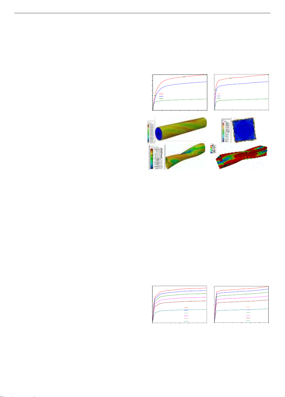
Figure 2-a,b depict the (𝑇 − 𝜃) curves for a column with
an axial load 𝑁𝑘 applied at an eccentricity of 𝑒 = 300𝑚𝑚
from the centroid. This setup simulates combined bending,
compression, and torsion. The analysis increments 𝑁𝑘 from
0 5 10 15 20 25 30
0
10
20
30
40
50
60
70
C
B
Concrete filled steel tube column
Pure steel tube
Pure concrete core
Torsion moment [kN.m]
CFST column has circular cross section with dimensions:
D x t x L: 139.8 x 4.5 x 2000
Steel tube has: fy=348.2MPa
Concrete core has: fcu=38.2MPa
CFST column bearing capacity under
simultaneous compressive, bending and torsional loads
A
[]
0 5 10 15 20 25 30
0
10
20
30
40
50
60
70
80
90
CFST column has square cross section with dimensions:
B x t x L: 139.8 x 4.5 x 2000
Concrete filled steel tube column
Pure steel tube
Pure concrete core
CFST column bearing capacity under
simultaneous compressive, bending and torsional loads
Concrete core has: fcu=38.2MPa
Steel tube has: fy=348.2MPa
Torsion moment [kN.m]
[]
0 5 10 15 20 25 30
0
10
20
30
40
50
60
70
[]
e=300mm; Nk=10kN
e=300mm; Nk=20kN
e=300mm; Nk=30kN
e=300mm; Nk=40kN
e=300mm; Nk=50kN
e=300mm; Nk=60kN
CFST column has circular cross section with dimensions:
D x t x L: 125 x 4.5 x 2000
Torsion moment [kN.m]
CFST column bearing capacity under
simultaneous compressive, bending and torsional loads
Concrete core has: fcu=30.4MPa
Steel tube has: fy=324.34MPa
0 5 10 15 20 25 30
0
10
20
30
40
50
60
70
80
[]
e=300mm; Nk=10kN
e=300mm; Nk=20kN
e=300mm; Nk=30kN
e=300mm; Nk=40kN
e=300mm; Nk=50kN
e=300mm; Nk=60kN
CFST column has square cross section with dimensions:
B x t x L: 110.78 x 4.5 x 2000
Torsion moment [kN.m]
CFST column bearing capacity under
simultaneous compressive, bending and torsional loads
Concrete core has: fcu=30.4MPa
Steel tube has: fy=324.34MPa
80 Pham My, Dinh Ngoc Hieu, Le Khanh Toan, Dang Cong Thuat
10kN to 60kN in 10kN steps, revealing a decreasing (𝑇 − 𝜃)
relationship. At 𝑁𝑘 of 40kN, the column's torsional
resistance drops sharply. The results illustrate how
increasing bending moments and axial loads generate shear
stresses that reduce both shear and torsional resistance.
We compare the circular column (Figure 2-a) and the
square column (Figure 2-b) at a 15° rotation angle with an
axial load of 𝑁𝑘=10𝑘𝑁. The circular column has a diameter
of 𝐷 = 125𝑚𝑚, a steel tube thickness of 𝑡 = 4.5𝑚𝑚,
a length of 𝑙 = 2000𝑚𝑚, a steel yield strength of
𝑓
𝑦=324.24𝑀𝑃𝑎, and a concrete compressive strength of
𝑓
𝑐𝑢 =30.4𝑀𝑃𝑎. The square column has a side length of
𝐵 = 110.78𝑚𝑚, with other properties identical to the
circular column. The torques are 62.8 kN.m for the circular
column and 75.4 kN.m for the square column. Thus, the
square column fails earlier and exhibits 16.72% higher torque
at a 15° rotation angle compared to the circular column.
For CFST columns under complex loading (bending,
compression, and torsion), increasing the eccentric axial
load reduces torsional resistance. Additionally, square
cross-sections fail earlier than circular ones.
a) Circular CFST columns
(D=139.8 mm)
b) Square CFST columns
(B=123.19 mm)
Figure 3. Investigate the relationship between rotation angle
and torque for CFT-Ci/Sq- Uk -9 model
The study proceeds under the same conditions as in
Figure 3-a,b, but with changes in the columns' geometry
and mechanical properties. For the circular column, the
diameter is 𝐷 = 139.8𝑚𝑚, steel thickness 𝑡 = 4.5𝑚𝑚,
length 𝑙 = 2000𝑚𝑚, yield strength 𝑓
𝑦=348.2𝑀𝑃𝑎, and
concrete compressive strength 𝑓
𝑐𝑢 =38.2𝑀𝑃𝑎. For the
square column, the side length is 𝐵 = 123.19𝑚𝑚, with
other parameters the same. Compared to Figure 2-a,b, the
column size increases by 10.59%, steel yield by 6.85%, and
concrete strength by 20.42%. Torque at 𝑁𝑘=10𝑘𝑁 and
200° rotation shows a 14.9% increase for the circular and
16.25% for the square column. Thus, with increased
parameters, the square column fails sooner.
4.2. Investigation of CFST columns subjected to
simultaneous compression and torsion
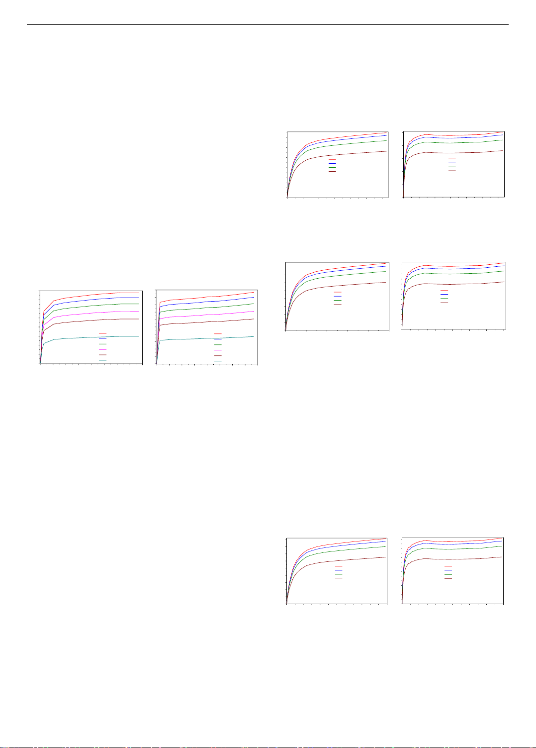
Figure 4-a,b analyze the load-bearing capacity through
the torque-rotation relationship, varying the axial load
influence (𝑛 = 𝑁𝑘𝑁𝑢
⁄). The study uses these parameters:
circular column (𝐷 = 114𝑚𝑚, 𝑡 = 4.5𝑚𝑚,
𝑙 = 1200𝑚𝑚, 𝑓
𝑦=280𝑀𝑃𝑎, 𝑓
𝑐𝑢 =21,9𝑀𝑃𝑎) and square
column (𝐵 = 101.03𝑚𝑚, with identical other properties).
As 𝑛 increases from 0.2 to 0.8 in 0.2 increments, torsional
resistance decreases. From Figure 7-a, when 𝑛 ≥ 0.5,
CFST columns' torque resistance drops rapidly. Thus,
increasing axial load reduces torsional resistance.
Comparing Figure 4-a,b and Figure 7-a reveals that the
square cross-section column reaches the ultimate torque
faster than the circular one, highlighting the importance of
slippage between the steel tube and concrete core in
torsional resistance. At a rotation angle of 150 and
𝑛 = 0.2, the circular column's torque is 35.2 kN.m, while
the square column's is 49.8 kN.m, meaning the square
column reaches the ultimate value 29.32% sooner.
a) Circular CFST columns
(D=114 mm)
b) Square CFST columns
(B=101.03 mm)
Figure 4. Investigate the relationship between rotation angle
and torque for CFT-Ci/Sq-Nk-6 model
a) Circular CFST columns
(D=125 mm)
b) Square CFST columns
(B=110.78 mm)
Figure 5. Investigate the relationship between rotation angle
and torque for CFT-Ci/Sq-Nk-2 model
Figure 5-a,b and Figure 7-b compares the torsional
capacity of CFST columns with circular and square cross-
sections, using modified geometric and mechanical
properties. For the circular column, 𝐷 = 125𝑚𝑚,
𝑡 = 4.5𝑚𝑚, 𝑙 = 1200𝑚𝑚, 𝑓
𝑦=324.24𝑀𝑃𝑎, and
𝑓
𝑐𝑢 =34.24𝑀𝑃𝑎; for the square column, B = 110.78mm,
with other parameters unchanged. The behavior mirrors that
in Figure 4-a,b and Figure 7-a. At a rotation angle of 150 and
𝑛 = 0.2, increasing column size by 8.8%, steel yield by
13.6%, and concrete strength by 36.04% raises torque by
9.51% for the circular column and 21.45% for the square. The
square column's torque surpasses the circular by 11.94%.
a) Circular CFST columns
(D=139.8 mm)
b) Square CFST columns
(B=123.19 mm)
Figure 6. Investigate the relationship between rotation angle
and torque for CFT-Ci/Sq-Nk-9 model
Figure 6-a,b and Figure 7-c assess the torsional capacity
of CFST columns with circular and square cross-sections
using different geometric and mechanical properties: For
the circular column, the diameter is 139.8mm, tube
thickness is 4.5mm, length is 1200mm, steel yield strength
0 5 10 15 20 25 30 35 40
0
10
20
30
40
50
60
70
80
[]
e=300mm; Nk=10kN
e=300mm; Nk=20kN
e=300mm; Nk=30kN
e=300mm; Nk=40kN
e=300mm; Nk=50kN
e=300mm; Nk=60kN
CFST column has circular cross section with dimensions:
D x t x L: 139.8 x 4.5 x 2000
Torsion moment [kN.m]
CFST column bearing capacity under
simultaneous compressive, bending and torsional loads
Concrete core has: fcu=38.2MPa
Steel tube has: fy=348.2MPa
0 5 10 15 20 25 30 35 40
0
10
20
30
40
50
60
70
80
90
100
[]
e=300mm; Nk=10kN
e=300mm; Nk=20kN
e=300mm; Nk=30kN
e=300mm; Nk=40kN
e=300mm; Nk=50kN
e=300mm; Nk=60kN
CFST column has square cross section with dimensions:
B x t x L: 123.19 x 4.5 x 2000
Torsion moment [kN.m]
CFST column bearing capacity under
simultaneous compressive, bending and torsional loads
Concrete core has: fcu=38.2MPa
Steel tube has: fy=348.2MPa
0.0 2.5 5.0 7.5 10.0 12.5 15.0
0
5
10
15
20
25
30
[]
CFST column has circular cross section with dimensions:
D x t x L: 114 x 4.5 x 1200
Coefficient n=0.2
Coefficient n=0.4
Coefficient n=0.6
Coefficient n=0.8
Torsion moment [kN.m]
CFST column bearing capacity under simultaneous compressive
and torsional loads
Concrete core has: fcu=21.9MPa
Steel tube has: fy=280MPa
0.0 2.5 5.0 7.5 10.0 12.5 15.0
0
10
20
30
40
50
[]
CFST column has square cross section with dimensions:
B x t x L: 101.03 x 4.5 x 1200
CFST column bearing capacity under simultaneous compressive
and torsional loads
Coefficient n=0.2
Coefficient n=0.4
Coefficient n=0.6
Coefficient n=0.8
Torsion moment [kN.m]
Concrete core has: fcu=21.9MPa
Steel tube has: fy=280MPa
0 5 10 15 20 25
0
5
10
15
20
25
30
35
40
[]
CFST column has circular cross section with dimensions:
D x t x L: 125 x 4.5 x 1200
CFST column bearing capacity under simultaneous compressive
and torsional loads
Coefficient n=0.2
Coefficient n=0.4
Coefficient n=0.6
Coefficient n=0.8
Torsion moment [kN.m]
Concrete core has: fcu=30.4MPa
Steel tube has: fy=324.34MPa
0 4 8 12 16 20 24
0
10
20
30
40
50
60
[]
CFST column has square cross section with dimensions:
B x t x L: 110.78 x 4.5 x 1200
CFST column bearing capacity under simultaneous compressive
and torsional loads
Coefficient n=0.2
Coefficient n=0.4
Coefficient n=0.6
Coefficient n=0.8
Torsion moment [kN.m]
Concrete core has: fcu=30.4MPa
Steel tube has: fy=324.34MPa
0 5 10 15 20 25 30
0
5
10
15
20
25
30
35
40
45
[]
CFST column has circular cross section with dimensions:
D x t x L: 139.8 x 4.5 x 1200
CFST column bearing capacity under simultaneous compressive
and torsional loads
Coefficient n=0.2
Coefficient n=0.4
Coefficient n=0.6
Coefficient n=0.8
Torsion moment [kN.m]
Concrete core has: fcu=38.2MPa
Steel tube has: fy=348.2MPa
0 5 10 15 20 25 30
0
10
20
30
40
50
60
70
[]
CFST column has square cross section with dimensions:
B x t x L: 123.19 x 4.5 x 1200
CFST column bearing capacity under simultaneous compressive
and torsional loads
Coefficient n=0.2
Coefficient n=0.4
Coefficient n=0.6
Coefficient n=0.8
Torsion moment [kN.m]
Concrete core has: fcu=38.2MPa
Steel tube has: fy=348.2MPa
ISSN 1859-1531 - THE UNIVERSITY OF DANANG - JOURNAL OF SCIENCE AND TECHNOLOGY, VOL. 22, NO. 11B, 2024 81
is 348.2MPa, and concrete compressive strength is
38.2MPa. For the square column, the side length is
123.89mm, with other parameters identical to the circular
column. The behavior aligns with the results in Figure 4-
a,b and Figure 7-a.
We analyze a typical case at a 150 rotation angle and an
axial load influence factor of 𝑛 = 0.2. Increasing the
column diameter by 18.45%, steel yield strength by
19.59%, and concrete compressive strength by 42.67%
results in a 18.52% increase in torque for the circular
column and a 46.83% increase for the square column. This
confirms that with equivalent size and material property
increments, the square column's torque increases by
28.31% more than the circular column.
a) Column 114×4.5×1200mm
b) Column 125×4.5×1200mm
c) Column 139.8×4.5×1200mm
Figure 7. Comparison of load-bearing capacity between circular and square columns under combined compression and torsion
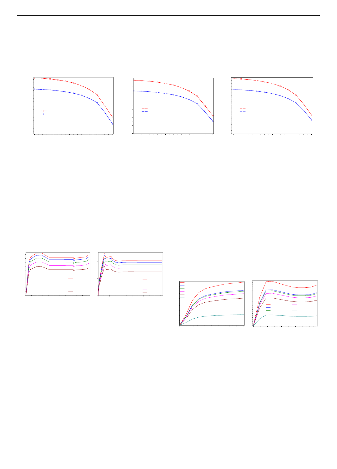
Figure 8-a,b assess how torque affects the strain-axial
compressive force relationship in the steel tube shell. For the
circular column, while the axial load initially increases
rapidly, strain in the steel tube rises slowly because the
concrete core shares some of the stress. As sliding begins,
the core transfers less stress to the steel tube, causing strain
to increase rapidly. This leads to plastic deformation in the
steel tube, marked by a yield plateau on the 𝑁 − 𝜀 curve. As
the axial load approaches the column's critical compressive
force, the steel tube reaches its ultimate strength. Eventually,
the tube loses its load-bearing capacity, and although the
load decreases, column strain continues to rise.
a) Circular CFST columns
b) Square CFST columns
Figure 8. Examine the correlation between axial force and
relative deformation
In the square column, sliding is more difficult, so the
concrete core continuously shares stress with the steel tube,
causing strain in the tube to increase slowly until the axial
load reaches the critical value. The column fails suddenly
and brittlely due to the concrete core (see Figure 8-b), even
though the steel tube has not reached its ultimate strength.
The steel then bears most of the load, reaching its yield
point before its strength value. Due to continuous cold
hardening, the steel's strength at a strain of 7340(𝜇𝜀) is
lower than for the circular column. The column then loses
load-bearing capacity, with axial load decreasing and strain
increasing until complete failure.
Figure 8-a,b illustrate that increased torque reduces the
axial compressive strength of the column. This occurs
because torque accelerates slippage between the steel tube
and the concrete core, thereby diminishing the column's
axial load-bearing capacity.
4.3. Investigation of CFST columns subjected to
simultaneous bending and torsion
This section investigates how bending moment affects
the torsional resistance of columns with circular and square
cross-sections, considering variations in geometric and
mechanical parameters. Figure 9-a,b shows the relationship
between torque and rotation angle under different bending
moment impacts (𝑀𝑘). For the circular column with 𝐷 =
114𝑚𝑚, 𝑡 = 4.5𝑚𝑚, 𝑙 = 1200𝑚𝑚, 𝑓
𝑦=280𝑀𝑃𝑎,
and 𝑓
𝑐𝑢 =21.9𝑀𝑃𝑎, and the square column with 𝐵 =
101.03𝑚𝑚, similar trends are observed. The results,
combined with Figure 12-a, reveal that increasing 𝑀𝑘
decreases torsional resistance due to the additional shear
forces generated by the bending moment, which, along
with torque-induced shear forces, reduces the column's
torsional strength.
a) Circular CFST columns
(D=114 mm)
b) Square CFST columns
(B=101.03mm)
Figure 9. Analyze the correlation between rotation angle and
torque for CFT-Ci/Sq- Uk -6 model
Figure 9 to Figure 11-b reveals that bending moments
shift the 𝑇 − 𝜃 curve away from the 𝑂𝑇 axis more than
axial loads (given in Figure 4 to Figure 6-b) which only
causes volumetric expansion and increases friction
between the steel tube and concrete core. This friction
limits slippage and reduces rotation. In contrast, bending
moments generate shear forces that ease slippage,
increasing rotation and shifting the 𝑇 − 𝜃 curve.
Comparing Figure 10-a,b, at a 50 rotation and
𝑀𝑘=14.15𝑘𝑁. 𝑚, the circular column’s torque is
27.5 kN.m, while the square column's torque approaches
70.2 kN.m. This shows the square column reaches failure
0.0 0.1 0.2 0.3 0.4 0.5 0.6 0.7 0.8 0.9 1.0
0
5
10
15
20
25
30
35
40
45
50
CFST column bearing capacity under simultaneous compressive and torsional loads
Torsion moment [kN.m]
Square column B x t x L: 101.03x4.5x1200
Round column D x t x L: 114x4.5x1200
Concrete core has: fcu=21.9MPa
Steel tube has: fy=280MPa
Nk/Nu
0.0 0.1 0.2 0.3 0.4 0.5 0.6 0.7 0.8 0.9 1.0
0
10
20
30
40
50
60
70
Nk/Nu
Square column B x t x L: 110.78x4.5x1200
Round column D x t x L: 125x4.5x1200
CFST column bearing capacity under simultaneous compressive and torsional loads
Torsion moment [kN.m]
Concrete core has: fcu=34.24MPa
Steel tube has: fy=324.24MPa
0.0 0.1 0.2 0.3 0.4 0.5 0.6 0.7 0.8 0.9 1.0
0
10
20
30
40
50
60
70
80
90
Nk/Nu
Square column B x t x L: 123.19x4.5x1200
Round column D x t x L: 139.8x4.5x1200
CFST column bearing capacity under simultaneous compressive and torsional loads
Torsion moment [kN.m]
Concrete core has: fcu=38.2MPa
Steel tube has: fy=348.2MPa
05000 10000 15000 20000 25000
0.0
0.2
0.4
0.6
0.8
1.0
T/Tu=0.0
T/Tu=0.2
T/Tu=0.4
T/Tu=0.6
T/Tu=0.8
CFST column has circular cross section with dimensions:
D x t x L: 139.8 x 4.5 x 1200
Effect of T/Tu on the relationship between compressive force N
and relative strain
Concrete core has: fcu=38.2MPa
Steel tube has: fy=348.2MPa
Nk/Nu
[]
05000 10000 15000 20000 25000
0.0
0.2
0.4
0.6
0.8
1.0
T/Tu=0.0
T/Tu=0.2
T/Tu=0.4
T/Tu=0.6
T/Tu=0.8
CFST column has square cross section with dimensions:
B x t x L: 123.19 x 4.5 x 1200
Effect of T/Tu on the relationship between compressive force N
and relative strain
Concrete core has: fcu=38.2MPa
Steel tube has: fy=348.2MPa
Nk/Nu
[]
0.0 2.5 5.0 7.5 10.0 12.5 15.0 17.5 20.0 22.5
0
5
10
15
20
25
30
35
40
45
[]
CFST column has circular cross section with dimensions:
D x t x L: 114 x 4.5 x 1200
Mk=10.82kN.m
Mk=27.72kN.m
Mk=32.445kN.m
Mk=34.86kN.m
Mk=35.91kN.m
Mk=44.21kN.m
Torsion moment [kN.m]
CFST column bearing capacity under simultaneous bending and torsional loads
Steel tube has: fy=280MPa
Concrete core has: fcu=21.9MPa
0.0 2.5 5.0 7.5 10.0 12.5 15.0 17.5 20.0 22.5
0
5
10
15
20
25
30
35
40
45
50
55
[]
CFST column has square cross section with dimensions:
B x t x L: 101.03 x 4.5 x 1200
Mk=34.86kN.m
Mk=35.91kN.m
Mk=44.21kN.m
Mk=10.82kN.m
Mk=27.72kN.m
Mk=32.445kN.m
CFST column bearing capacity under simultaneous bending and torsional loads
Torsion moment [kN.m]
Steel tube has: fy=280MPa
Concrete core has: fcu=21.9MPa


![Giáo trình Cấu trúc dữ liệu và giải thuật - Trường CĐ Cơ điện Hà Nội [Mới nhất]](https://cdn.tailieu.vn/images/document/thumbnail/2026/20260323/lionelmessi01/135x160/58171774381670.jpg)


![Giáo trình Tiện nâng cao (Nghề Cắt gọt kim loại, Trình độ Cao đẳng) - Trường Cao đẳng Cơ điện Hà Nội [Mới nhất]](https://cdn.tailieu.vn/images/document/thumbnail/2026/20260323/lionelmessi01/135x160/48101774403543.jpg)


