Journal of Science and Technique - ISSN 1859-0209
75
INFLUENCE OF TRANSVERSE GROOVE SPACING
ON HYDROPLANING RISK AT AIRPORT
Huu Lam Nguyen1,*, Van Hieu Nguyen1, Duy Khanh Duong1
1Institute of Techniques for Special Engineering, Le Quy Don Technical University
Abstract
Hydroplaning is a dangerous phenomenon during operations at airports that causes loss of
control of aircraft during takeoff and landing. In tropical climates with high average annual
rainfall like Vietnam, the risk of hydroplaning is very high. Currently, the commonly used
solution is to cut transverse grooves on the runway surface. To evaluate the influence of
groove spacing on hydroplaning, the article uses CFD simulation with Ansys Fluent software
to determine the impact of groove spacing for 2 cases of A350-900 and A321-200 aircraft.
From the research results, it can be affirmed that the smaller the groove spacing is more risk
of hydroplaning is reduced. To ensure the stability of the structure, the groove spacing should
not be less than 38 mm (center-to-center) according to the recommendations of FAA and
many aviation organizations under ICAO.
Keywords: Hydroplaning; runway; airport; Ansys Fluent; CFD; transverse groove.
1. Introduction
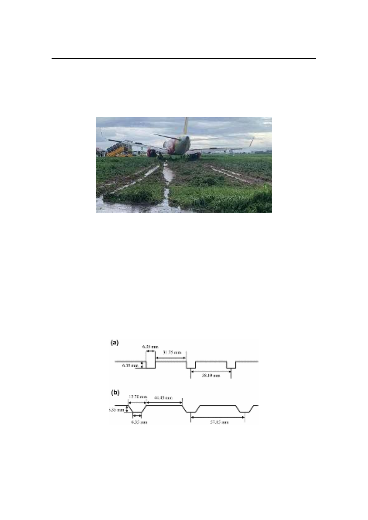
Hydroplaning, also known as aquaplaning, causes the moving wheel of an aircraft
to lose contact with the runway surface on which it is rolling with the result that braking
action on the wheel is not effective in reducing the ground speed of the aircraft.
- Dynamic hydroplaning [1]: arises when the aircraft travels over a puddle or a
flooded section of pavement, causing completely separate the aircraft tires from the
runway pavement surface. Most researchers refer to dynamic hydroplaning as
hydroplaning, as it is the most commonly encountered form on runways.
- Visco hydroplaning [1]: occurs specifically on surfaces with minimal microtexture.
In such cases, a thin fluid layer persists between the tire and the pavement due to the lack
of microtexture to disrupt it. Unlike dynamic hydroplaning, which is speed-dependent,
viscous hydroplaning can happen at any speed and with any fluid film depth.
- Reverted rubber hydroplaning [1]: occurs exclusively when large vehicles, such
as trucks or aircraft, lock their wheels while traveling at high speeds on wet pavements
with high macrotexture but minimal microtexture. The friction generated by the sliding
* Corresponding author, email: nguyenhuulam1995@lqdtu.edu.vn
DOI: 10.56651/lqdtu.jst.v7.n02.889.sce
Section on Special Construction Engineering - Vol. 07, No. 02 (Dec. 2024)
76
motion on the pavement heats up the tread rubber, causing it to revert and liquefy.
Consequently, the tire glides on a cushion composed of molten rubber, water, and steam.
This type of hydroplaning not only implicates wet traction mechanisms but also involves
the wear mechanism of rubber under elevated temperatures.
Fig. 1. Aircraft skid accident due to hydroplaning at Tan Son Nhat airport in 2020.
The solution to roughen the runway surface (including microtexture and
macrotexture) is the most basic solution to create friction between aircraft tires when
moving on the runway. To improve braking performance on the runway, in addition to the
surface roughening solution, creating a surface with good drainage capacity, converting
from wet friction coefficient to dry friction coefficient [1] with a higher value is a popular
solution, which is the solution to construct a runway pavement surface transverse groove.
Transverse grooves are cut horizontally on the runway surface, with specified
dimensions and distances [2], constructed on the surface of the runway after completion,
with the aim of quickly draining surface water, improving surface friction conditions, and
reducing the risk of dynamic hydroplaning.
Fig. 2. Dimensions of transverse groove according to FAA’s recommendation [2]
a) Square grooves; b) Trapezoidal grooves.
Journal of Science and Technique - ISSN 1859-0209
77
2. Hydroplaning simulation analysis
In a stationary observer frame of reference, the hydroplaning phenomenon can be
simulated by a locked wheel moving at a speed of U (m/s) sliding on a smooth pavement
flooded with water. In a moving wheel frame of reference, the problem can be modeled
as a jet comprising of a layer of air and a layer of water, and a smooth plane pavement
surface all moving at a speed of U (m/s) towards the wheel using a steady-state analysis.
Hydroplaning is assumed to occur when the average ground hydrodynamic pressure is
equivalent to the tire pressure of the wheel, i.e. when the aircraft load is equal to the
hydrodynamic lift force [1].
Fig. 3. Concept of hydroplaning modeling
1 - stationary wheel; 2 - inlet water; 3 - tire-pavement contact area; 4 - splash water;
5 - water move between tire and pavement.
Based on the above concept, the research of Ong and Fwa [1] built a simulation
model of hydroplaning and analyzed it using Ansys Fluent software.
Fig. 4. Geometry of the model (Dimensions are in mm).
The simulation based on the fundamental laws of turbulent flow [1]:
a) Continuity equation
0u
t
(1)
Section on Special Construction Engineering - Vol. 07, No. 02 (Dec. 2024)
78
where ρ is density of fluid, u is velocity of fluid, t is time.
b) The momentum Navier-Stokes equations
yx
xx zx
x
up
uU f
t x x y z



xy yy zy
y
vp
vU f
t y x y z

yz
xz zz
z
wp
wU f
t z x y z

where fx,y,z are body forces, p is pressure on the surface by surrounding elements, τ is the
shear and normal stresses on surface by friction, u, v, w represent x-velocity, y-velocity,
z-velocity, respectively.
c) Equations k-ε
2
t
t ij ij
k
kku k E E
t




2
12
2
t
t ij ij
u C E E C
t k k

 




(3)
where k is the turbulent kinetic energy, ε is the viscous dissipation.
The standard k-ε model employs values for the constants that arrive at by
comprehensive data fitting for a wide range of turbulent flows: Cμ = 0.09; σk = 1.00;
σε = 1.30; σ1ε = 1.44, and σ2ε = 1.92.
3. Analysis of the influence of transverse groove spacing on hydroplaning
To analyze the influence of transverse groove spacing (center-to-center) on the
hydroplaning phenomenon, the article chooses to analyze for 2 representative aircraft
types, A321-200 and A350-900, with the condition that the runway surface has transverse
grooves of size 6.35 mm × 6.35 mm (according to FAA's recommendation); the groove
spacing takes the values of 10, 20, 32, 38, 52 mm (center-to-center, according to FAA's
recommendation, China, Australia, Canada). The velocity of the water and air phases is
taken according to the operating velocity of each type of aircraft. The thickness of the
water layer is taken as 5 mm [1]. For each simulation analysis, the results determine the
pressure formed under the aircraft tire, the hydroplaning occurs when this pressure is
greater than the tire pressure of the aircraft.
Aircraft parameters are taken from Table 1.
Journal of Science and Technique - ISSN 1859-0209
79
For each set of transverse groove length, width and spacing values, the simulation
is performed by adjusting the surface condition and keeping the velocity value constant.
Table 1. Aircraft parameters
Type
Maximum load
(kg)
Landing
velocity
(km/h)
Landing
velocity
(m/s)
Tire pressure
(kPa)
A321-200
93500
220
61.1
1282.4
A350-900
275000
260
72.2
1660
Table 2. Dimension of transverse groove used in simulation
Length (mm)
Width (mm)
Spacing (mm)
6.35
6.35
10; 20; 32; 38; 52
The water phase in the model separates into two parts: one part collides with the
tire and splashes upwards, the other part moves between the tire and the runway surface,
causing the water layer pressure to increase to a certain value.
Fig. 1. Water volume fraction in result.
Fig. 2. Pressure under the aircraft tire.