
CÔNG NGHỆ https://jst-haui.vn Tạp chí Khoa học và Công nghệ Trường Đại học Công nghiệp Hà Nội Tập 60 - Số 8 (8/2024)
110
KHOA H
ỌC
P
-
ISSN 1859
-
3585
E
-
ISSN 2615
-
961
9
EVALUATION OF THE EFFECT OF THE AIR GAP SIZE TO THE AIR DISTRIBUTION IN CHAMBER DRYING EQUIPMENT VIA CFD METHOD
ĐÁNH GIÁ ẢNH HƯỞNG KÍCH THƯỚC KHÔNG GIAN CHIA GIÓ ĐẾN PHÂN BỐ TÁC NHÂN SẤY TRONG THIẾT BỊ SẤY BẰNG PHƯƠNG PHÁP CFD Nguyen Duc Trung1, Nguyen Duc Nam2, Cao Xuan Bac1, An Dai Duc1, Nguyen Duc Huy1, Pham Duc Binh1, Nguyen Huu Khai1, Nguyen Thi Thao1, Dang Minh Hieu3,* DOI: http://doi.org/10.57001/huih5804.2024.273 1. INTRODUCTION The drying product quality can be improved by optimizing the design of the drying equipment, with an inlet duct design [1] and inlet gap size and roof angle [2] in different types of drying equipment. The previous study only focuses on the appropriate value of angle [3], so this result does not create a totally optimal design. This study focuses on the effect of equipment dimension on product moisture homogeneity. Meshing and setting boundary conditions significantly affect the CFD simulation results. Meshing with higher-quality unstructured meshes leads to more accurate CFD simulation but increases time and cost [4]. The meshing has to be tuned appropriately for each case study to obtain both convergence and less computational time. When dealing with complex geometries, using a combination of structured and unstructured meshes is recommended for meshing [5]. The boundary conditions need to be exactly determined for the complete description of the drying process [6]. In mesh generation, discretization error is a common problem that can reduce the
ABSTRACT
This study evaluates the effect of the air gap size (d) on the air uniformity in the chamber
dryer with the
most appropriate air blade angle value inherited from the previous study.
Several case studies with different values of “d” are tested. The most appropriate ratio value
is 1/2; when criterion values reach the best values, show a significant improvement in
the air
received by the trays and the air uniformity in the equipment. Furthermore, several cases of
tray and equipment length are also tested, and they also affect the air distribution.
Keywords: CFD, drying process, uniform drying, tray dryer, COMSOL multiphysics.
TÓM T
ẮT Nghiên cứu đánh giá ảnh hưởng của khoảng giữa các khay và cửa gió vào đ
ến độ đồng
đ
ều không khí trong thiết bị sấy khay dạng buồng với giá trị α thích hợp nhất được tìm th
ấy
trong
bài nghiên cứu trước. Các giá trị khác nhau đã được thử nghiệm. Tiêu chuẩn va
, Sv, Δv
c
ũng được sử dụng để đánh giá độ đồng đều không khí trong thiết bị sấy. Tỉ lệ thích hợp nhất
là
1/2; sự giảm của S%, Δv và sự tăng của va cho thấy sự cải thiện đáng kể về lư
ợng không khí
nh
ận được từ các khay và độ đồng đều của không khí trong thiết bị. Hơn nữa, một số trư
ờng
h
ợp về chiều dài khay và chiều dài thiết bị đã được thử nghiệm, và chúng cũng có ảnh hư
ởng
t
ới sự phân bố không khí trong thiết bị. Từ khóa: CFD, quá trình sấy, sấy đồng đều, thiết bị sấy dạng khay, COMSOL multiphysics.
1
School of Chemistry and Life Sciences, Hanoi University of Science and Technology, Vietnam
2
Faculty of Electrical Engineering, Hanoi University of Industry, Vietnam
3
Vietnam Japan University, Vietnam National University, Hanoi, Vietnam
*
Email: dm.hieu@vju.ac.vn
Received: 10/12/2023
Revised: 18/4/2024
Accepted:
27/8/2024
P-ISSN 1859-3585 E-ISSN 2615-9619 https://jst-haui.vn SCIENCE - TECHNOLOGY Vol. 60 - No. 8 (Aug 2024) HaUI Journal of Science and Technology 111
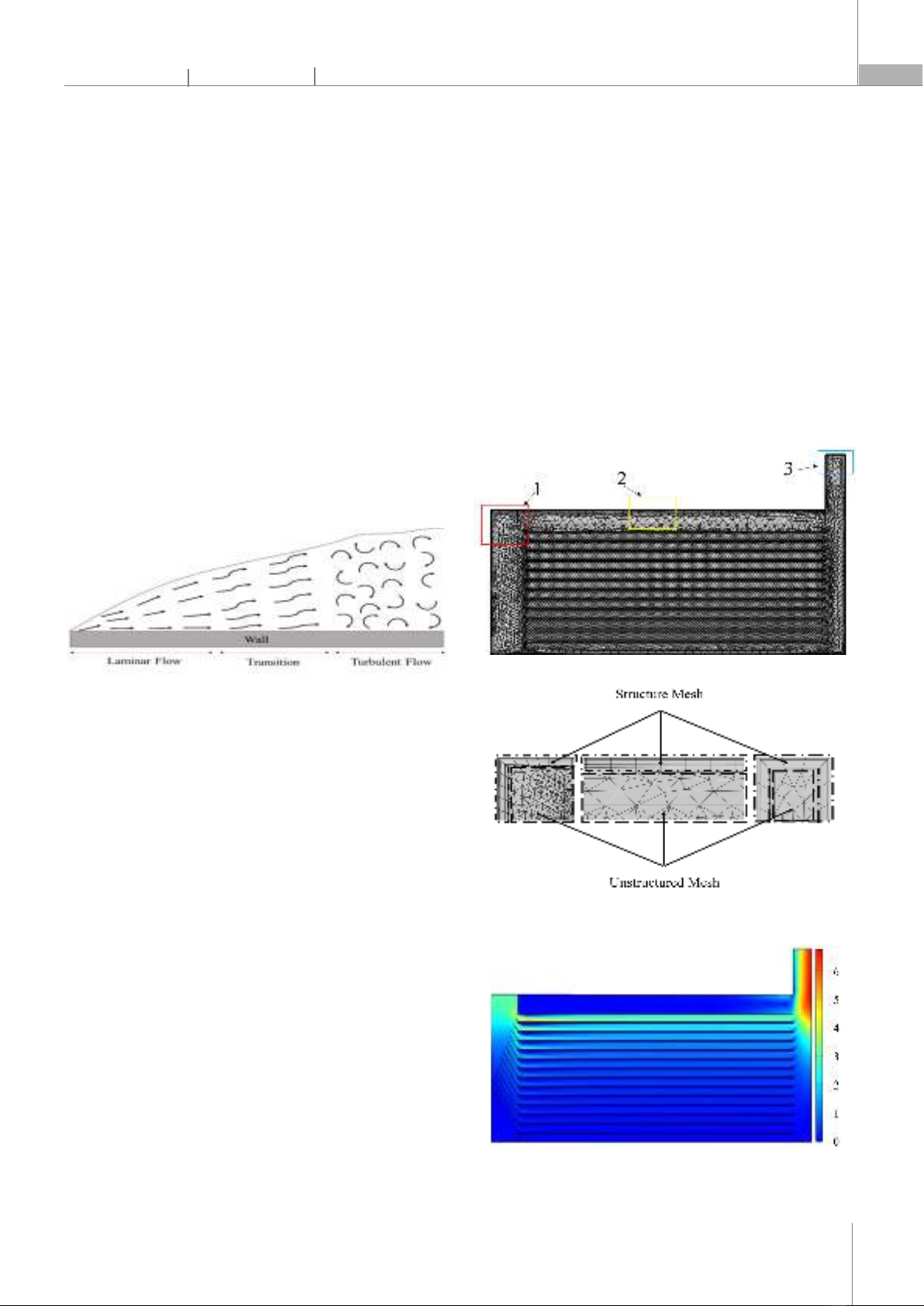
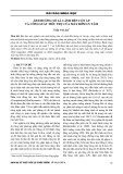
accuracy and stability of simulations. Discretization error occurs when the mesh is not fine enough to accurately represent the geometry of the problem domain. To evaluate the mesh quality, the skewness and non-orthogonality of grid elements are used as criteria [7]. Meshes with high skewness and non-orthogonality are more likely to produce inaccurate results. Adaptive mesh refinement is a common method for reducing discretization error; adaptive mesh refinement has different techniques: reducing the element size, increasing element order, etc. [8]. 2. MATERIALS AND METHODS 2.1. Modeling and simulation setup There are three main types of fluid flow: laminar flow, transitional flow, and turbulent flow, generally based on the Reynolds numbers of fluid. The Navier-Stokes equations are a set of nonlinear partial differential equations (PDEs) that govern the motion of fluids. Fig. 1. Three main types of fluid flow The Navier-Stokes equations solution is affected by two crucial factors: mesh quality and boundary conditions [9]. In turbulent flow mode, near walls, where the viscous shear stress is much stronger than the turbulent shear stress, a thin layer of fluid called the viscous layer is formed [10]. In this layer, the velocity gradient is so steep that the fluid velocity decreases to zero at the wall within a short distance. Using no-slip boundary conditions, which means fluid velocity near a wall is zero, making the velocity gradient even steeper. Slip boundary conditions allow non-zero velocity near walls, reducing the steepness of the velocity gradient and making it easier to solve. The model and boundary conditions for simulations are set the similar as [3]. The air gap size (d) and the chamber length (l) are tuned to evaluate the effect on air distribution in this study. 2.2. Meshing method Conforming mesh improves the accuracy of the solution near boundaries [11]. The convergence speed of the solution is highly affected by mesh quality [12]. The air blade, inlet, outlet, and material surface mainly affect the results, so they are meshed with unstructured meshes. The others are coarsely meshed to save simulation time without affecting the results. A boundary layer is a thin layer of fluid near a solid surface where the flow properties change rapidly, and it must be thin enough to fit meshing standards. Using structured meshes near walls causes the walls in the chamber to be typically flat and appropriate for the simulation of the viscous thin layer near the wall. The corner refinement method is used to improve solution accuracy in areas with sharp corners or edges. Cases with higher mesh density result in much finer velocity and pressure contours [13], using the mesh refinement technique to increase mesh density near the material surface. Fig. 2. Simulation mesh of chamber Fig. 3. Structured Mesh and Unstructured Mesh in the chamber 3. RESULT AND DISCUSSION a)
CÔNG NGHỆ https://jst-haui.vn Tạp chí Khoa học và Công nghệ Trường Đại học Công nghiệp Hà Nội Tập 60 - Số 8 (8/2024)
112
KHOA H
ỌC
P
-
ISSN 1859
-
3585
E
-
ISSN 2615
-
961
9
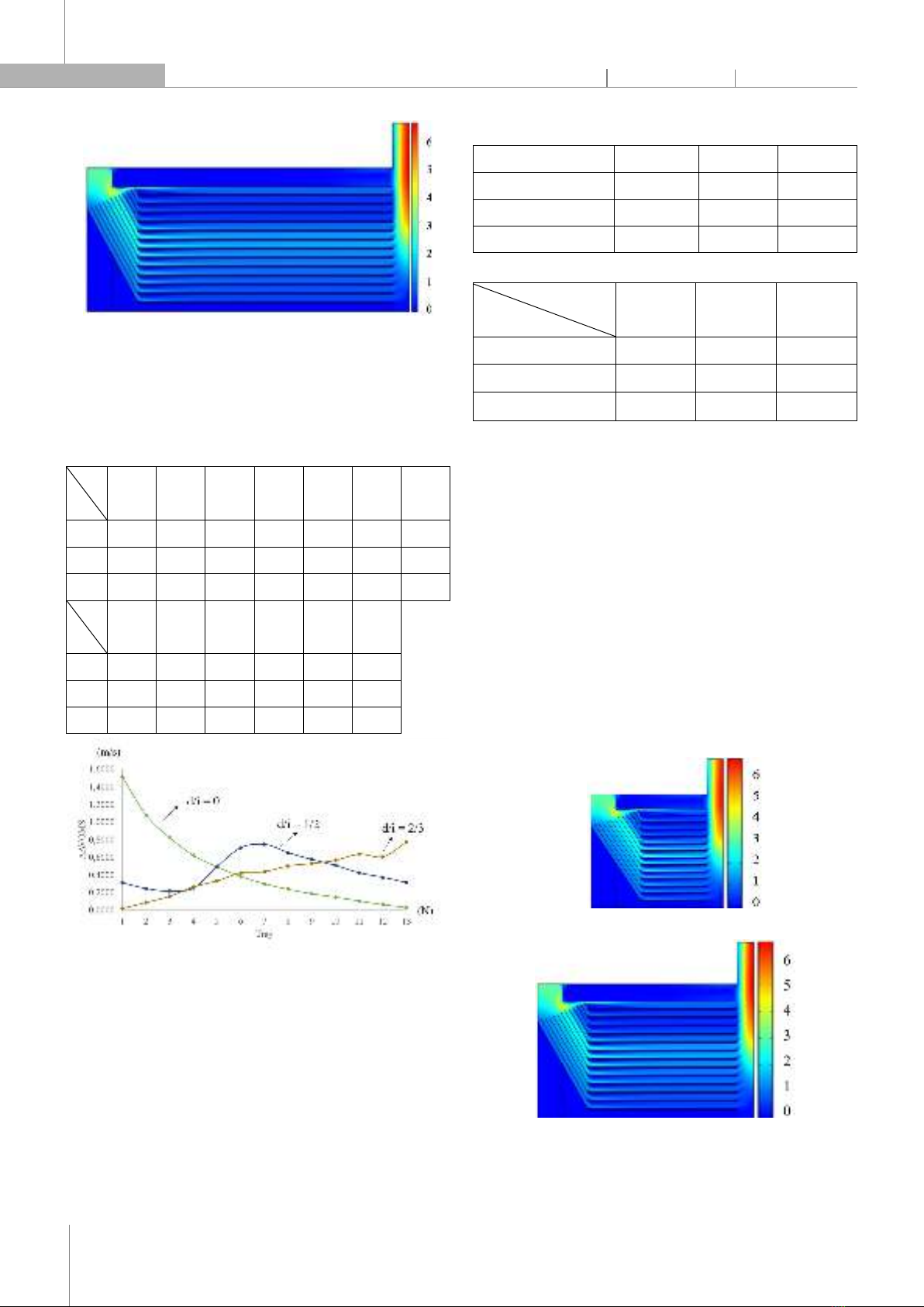
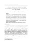
b) Fig. 4. a) d/i = 0; b) d/i = ½ The chamber dryer is simulated in three cases with different ratios of air gap size (d) and inlet (i). The parameter d is changed, and i is constant. Table 1. Simulation results of AAVOMS (m/s) Tray
d/i 1 2 3 4 5 6 7 0 1.5109 1.0776 0.8224 0.6230 0.4899 0.3800 0.2982 1/2 0.3112 0.2444 0.2164 0.2507 0.4949 0.7091 0.7481 2/3 0.0184 0.0877 0.1574 0.2637 0.3321 0.4221 0.4353 Tray
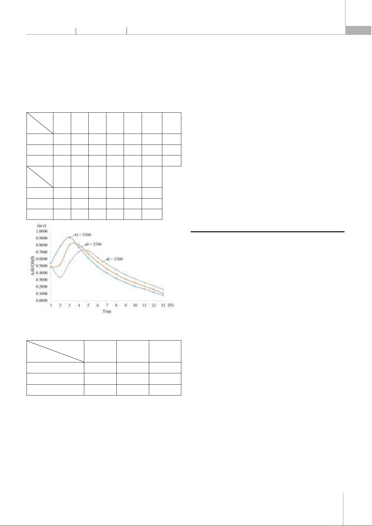
d/i 8 9 10 11 12 13 0 0.2363 0.1871 0.1451 0.1038 0.0627 0.0310 1/2 0.6523 0.5766 0.5086 0.4238 0.3718 0.3130 2/3 0.4996 0.5252 0.5655 0.6368 0.6042 0.7729 Fig. 5. AAVOMS on each tray in each d/i value In case 1 (d/i = 0), tray 13 has minimum AAVOMS (0.0310m/s), and the first tray has maximum AAVOMS (1.5109m/s). When comparing case 2 (d/i = 1/2) to case 1, the minimum and maximum AAVOMS respectively change to tray 3 and tray 7; tray 1 has less air through the surface than in case 1 (lower AAVOMS). The final case (d/i = 2/3) is opposite to case 1: tray 1 has minimum AAVOMS (0.0184m/s), and tray 13 has maximum AAVOMS (0.7729m/s). Table 2. Max and Min AAVOMS in the chamber d/i 0 1/2 2/3 Nmax 1 7 13 Nmin 13 3 1 Diff. 12 -4 -12 Table 3. Criterion calculated for different d/i values d/i
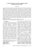
Criterion 0 1/2 2/3 va 0.4591 0.4478 0.4093 S% (%) 96.80 40.76 55.34 Δv 3.2236 1.1873 1.8434 The criteria va decreases from 0.4591 at d/i = 0 to 0.4093 at d/i = 2/3. The va values at d/i = 0 and 1/2 are not significantly different, which means the amount of air through all material surfaces is approximately in these two cases. The S% value decreases from 96.80% to 40.76%, then increases to 55.34%. If d/i is more or less than 1/2, the relative variability of the AAVOMS set increases. Case 2 has the least relative variability of the AAVOMS set compared with other cases. The Δv value in this case significantly decreases, meaning the difference between the minimum and maximum values in the AAVOMS set decreases when d/i decreases. Δv is approximate in cases 2 and 3. It can be concluded that case 2 with d/i = 1/2 is the best among the others. a) b) Fig. 6. Equipment length: a) 1500 mm; b) 2500 mm
P-ISSN 1859-3585 E-ISSN 2615-9619 https://jst-haui.vn SCIENCE - TECHNOLOGY Vol. 60 - No. 8 (Aug 2024) HaUI Journal of Science and Technology 113
The most appropriate d/i value (1/2) of all case studies above is used to improve the air uniformity of the equipment. Different equipment lengths (l): 1,500, 2,500, and 3,500 (mm) are simulated with the same boundary conditions as all cases above. Table 4. Simulation results of average velocity on the material surface (AAVOMS, m/s) Tray
l (mm) 1 2 3 4 5 6 7 1500 0.4984
0.3327
0.5463
0.7043
0.7167
0.6190 0.5260
2500 0.4777
0.5202
0.8024
0.8021
0.6733
0.5558 0.4561
3500 0.5362
0.7790
0.9144
0.7666
0.6144
0.4890 0.3964
Tray
l (mm) 8 9 10 11 12 13 1500 0.4441
0.3705
0.3126
0.2594
0.2109
0.1567 2500 0.3775
0.3064
0.2543
0.2069
0.1596
0.1037 3500 0.3183
0.2577
0.2059
0.1660
0.1196
0.0748 Fig. 7. AAVOMS on each tray in each case Table 5. Criterion calculated for different equipment length l (mm) Criterion 1,500 2,500 3,500 va 0.4383 0.4381 0.4337 S% (%) 41.58 52.73 63.28 Δv 1.2777 1.5946 1.9357 Changing the equipment length changes the air distribution. The equipment height also affects the air distribution, but due to operational restrictions, it is limited. It is not necessary to consider the effect of the height of the equipment on the air distribution. 4. CONCLUSION Despite installing, tuning, and finding out the best air blade angle value in the previous study which makes the air distribution better, it can be improved more. In this study, the air gap size is tuned, and the most appropriate result is d/i = 1/2. It can be concluded that the bigger the air gap size, the better the air uniformity, as well as the better the final product quality (but if d/i exceeds ½, the air distribution may be worse). After that, the air distribution is also evaluated by changing the trays and equipment length, and 1500mm is the best one. In short, the whole study demonstrates the effect of the air blade angle, the air gap size (d) and the equipment length on the air uniformity in the chamber dryer. It also shows how to set the boundary conditions and mesh to obtain the best simulation results using COMSOL Multiphysics - a useful software for simulating. However, to approach the completely optimal design as well as apply it to the actual design, further research on 3D modeling is necessary.
REFERENCES [1]. P. J. Etim, A. B. Eke, K. J. Simonyan, “Effect of air inlet duct features and greater thickness on cooking banana drying characteristics using active indirect mode solar dryer,” Nigerian Journal of Technology (NIJOTECH), 38/4, 1056 - 1063, 2019. [2]. Agyei-Agyemang Anthony, Obeng George Yaw, Afriyie John Kwasi, Asaaga Benjamin Atribawuni, “Effects of roof angle, inlet gap size and dryer height on temperature and relative humidity in a chimney-dependent solar crop dryer,” Renewable Energy and Environmental Sustainability, 7/18, 1-10, 2022. [3]. Nguyen Duc Trung, et al., “Evaluation of the effect of air blade angle on air distribution in chamber drying equipment via CFD method,” Journal of Science and Technology, Hanoi University of Industry, 60, 4, 100-104, 2024. [4]. Blazek J., Computational Fluid Dynamics: Principles and Applications. Elsevier Science: Amsterdam, Netherlands, 2015. [5]. Andreas Lintermann, Computational Meshing for CFD Simulations, Clinical and Biomedical Engineering in the Human Nose - A Computational Fluid Dynamics Approach. Springer Nature Singapore Pte Ltd, Singapore, 2020. [6]. Pieter Wesseling, Principles of Computational Fluid Dynamics. Springer, Germany, 2001. [7]. Park G., Kim C., Lee M., Choi C., “ Building Geometry Simplification for Improving Mesh Quality of Numerical Analysis Model,” Applied Sciences, 10/16, 5425, 2020. [8]. COMSOL 6.0 documentation. Accessed 19 August 2023. https://doc.comsol.com/6.0/docserver/#!/com.comsol.help.comsol/helpdesk/helpdesk.html

CÔNG NGHỆ https://jst-haui.vn Tạp chí Khoa học và Công nghệ Trường Đại học Công nghiệp Hà Nội Tập 60 - Số 8 (8/2024)
114
KHOA H
ỌC
P
-
ISSN 1859
-
3585
E
-
ISSN 2615
-
961
9
[9]. J. D. Anderson, Computational Fluid Dynamics: The Basics with Applications. McGraw-Hill, Inc, USA, 1995. [10]. Kumar S. S., Huang X., Yang X., Hong J., “Three-dimensional flow motions in the viscous sublayer,” Theoretical and Applied Mechanics Letters, 11/2, 2021. [11]. H. K. Versteeg, W. Malalasekera, An Introduction to Computational Fluid Dynamics Second Edition. Prentice Hall, USA, 2002. [12]. Aqilah F., Islam M., Juretic F., Guerrero J., Wood D., Ani F. N., “Study of mesh quality improvement for CFD analysis of an airfoil,” IIUM Eng. J., 19/2, 203-212, 2018. [13]. T. Sencic, V. Mrzljak, J. Batista, O. Bukovac, “Influence of Mesh and Combustion Parameters on a Spark Ignition Engine CFD Simulation,” FME Transaction, 51/3:374-385, 2023. [14]. Filios Andronikos, Alexandros Vouros, Dionissios Margaris, Achilleas Bardakas, Dimitrios Tzempelikos, “Design, construction, and evaluation of a new laboratory convective dryer using CFD,” International Journal of Mechanics, 7/4, 425-434, 2013. [15]. Filios Andronikos, Alexandros Vouros, Dionissios Margaris, Achilleas Bardakas, and Dimitrios Tzempelikos, “Analysis of air velocity distribution in a laboratory batch-type tray air dryer by computational fluid dynamics,” International Journal of Mathematics and Computers in Simulation, 6/5, 413-421, 2012. [16]. Lamnatou C., E. Papanicolaou, V. Belessiotis, N. Kyriakis, “Finite-volume modeling of heat and mass transfer during convective drying of porous bodies - non-conjugate and conjugate formulations involving the aerodynamic effects,” Renewable Energy, 35/7, 1391-1402, 2010. [17]. Amanlou Y., A. Zomorodian, “Applying CFD for designing a new fruit cabinet dryer,” Journal Review of solid/liquid desiccant in the drying of Food Engineering, 101/1, 8-15, 2010. THÔNG TIN TÁC GIẢ Nguyễn Đức Trung1, Nguyễn Đức Nam2, Cao Xuân Bắc1, An Đại Đức1, Nguyễn Đức Huy1, Phạm Đức Bình1, Nguyễn Hữu Khải1, Nguyễn Thị Thảo1, Đặng Minh Hiếu3 1Trường Hóa và Khoa học sự sống, Đại học Bách khoa Hà Nội 2Khoa Điện, Trường Đại Học Công nghiệp Hà Nội. 3Trường Đại học Việt - Nhật, Đại học Quốc gia Hà Nội


![Giáo trình Cấu trúc dữ liệu và giải thuật - Trường CĐ Cơ điện Hà Nội [Mới nhất]](https://cdn.tailieu.vn/images/document/thumbnail/2026/20260323/lionelmessi01/135x160/58171774381670.jpg)


![Giáo trình Tiện nâng cao (Nghề Cắt gọt kim loại, Trình độ Cao đẳng) - Trường Cao đẳng Cơ điện Hà Nội [Mới nhất]](https://cdn.tailieu.vn/images/document/thumbnail/2026/20260323/lionelmessi01/135x160/48101774403543.jpg)


