
Journal of Science and Technique - ISSN 1859-0209
83
CALCULATION OF THE DRAFT OF THE FLOATING
BRIDGE BUILT FROM PLASTIC BUOYS
WHEN THE LOAD IS A TRUCK
Manh Thuong Nguyen1,*, Thi Thu Hien Dang1, Ngoc Hai Nguyen1
1Institute of Techniques for Special Engineering, Le Quy Don Technical University
Abstract
In some emergency traffic situations such as rescue, natural disasters,... it is necessary to
build a temporary bridge to cross the river. Using a quick-assembled floating bridge made of
plastic buoys is the appropriate solution. This article presents the study of calculating the
draft of continuous floating bridge assembled from plastic buoys. The author calculates the
draft by two different methods, which are theoretical calculation and finite element modeling
using SAP2000 software, to verify the discrepancy of the results of these two methods. The
results obtained show that the discrepancy between these two methods is insignificant, and
continuous floating bridge assembled with a layer of plastic buoys can withstand a small
truck load of up to 12.3 tons.
Keywords: Floating bridge; plastic buoy; truck; draft; elastic background.
1. Introduction
In our country, in some emergency traffic situations such as rescue, natural
disasters, repairing old bridges, etc., it is necessary to build a temporary bridge to cross
the river [1-3]. When the load requirement is not large, a floating bridge assembled from
plastic buoys is one of the feasible and suitable options. Pedestrian floating bridges
assembled from these plastic buoys are being used today. However, there are no
documents or actual projects using this type of bridge for vehicles with gross vehicle
weight up to 12.3 tons. Therefore, in-depth research and practical tests are needed to
evaluate the demand before applying it in practice. In this article, the authors focus on
calculating the draft of continuous floating bridge when withstanded to the load of small
trucks up to 12.3 tons. It is the scientific basis for evaluating the applicability of this type
of bridge in practice.
2. Scientific basis for calculating the draft of floating bridges assembled
from plastic buoys
2.1. Introduction to plastic buoys of floating bridge
In our country today, plastic buoys are increasingly widely used in many fields.
* Corresponding author, email: thuongnm@lqdtu.edu.vn
DOI: 10.56651/lqdtu.jst.v7.n02.872.sce
Section on Special Construction Engineering - Vol. 07, No. 02 (Dec. 2024)
84
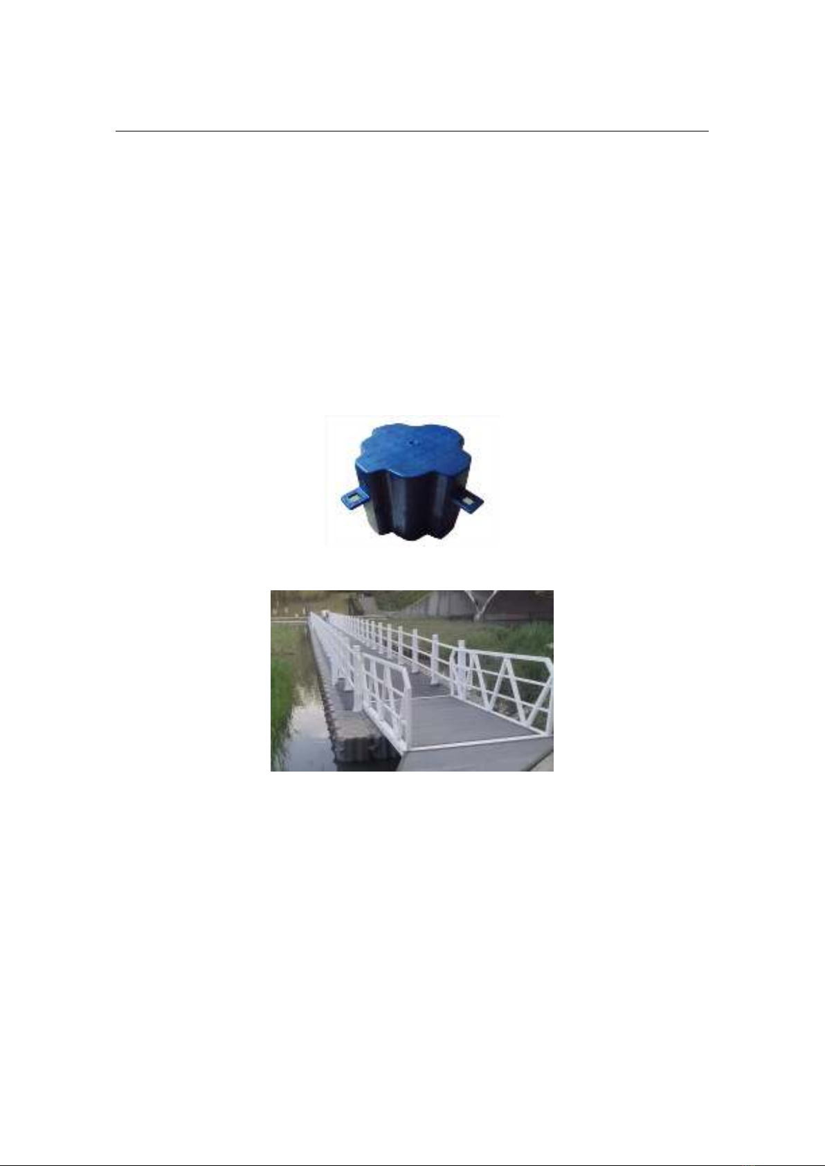
Plastic buoys are floating blocks made from HDPE plastic. Floating plastic buoys are
designed in modular form, and can be certainly connected to each other continuously in
3 dimensions. Dimensions of 1 float are 500 mm × 500 mm × 430 mm (length × width ×
height), and float weight is about 6.3 kg [4]. Physical properties of HDPE plastic materials
include: Density (0.95 g/cm³), and elastic modulus (E = 995 MPa) [5, 6]. Floating plastic
buoys have many advantages such as: easy to transport, relocate, install, dismantle, and
change structure shape as desired; short installation time; low installation cost (because
of modular installation details); high buoyancy (because of lightweight), and highly
durability. Floating plastic buoys can form a flat surface on the water so it is very
convenient to assemble into a floating bridge.
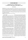
Fig. 1. Plastic buoy.
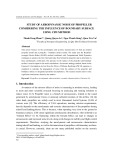
Fig. 2. The pedestrian floating bridge is assembled from floating plastic buoys.
2.2. Scientific basis for calculating the draft of continuous floating bridges
The floating bridges that are assembled from plastic buoys are continuous floating
bridge. Calculating the draft of this type of floating bridge is a complicated problem. In
this article, the authors use a beam model on an elastic foundation to calculate the draft
of a continuous floating bridge, and presents two methods for determining the draft of
this type of floating bridge. The first method is an analytical method, and the second
method is a finite element method using SAP2000 software.
Journal of Science and Technique - ISSN 1859-0209
85
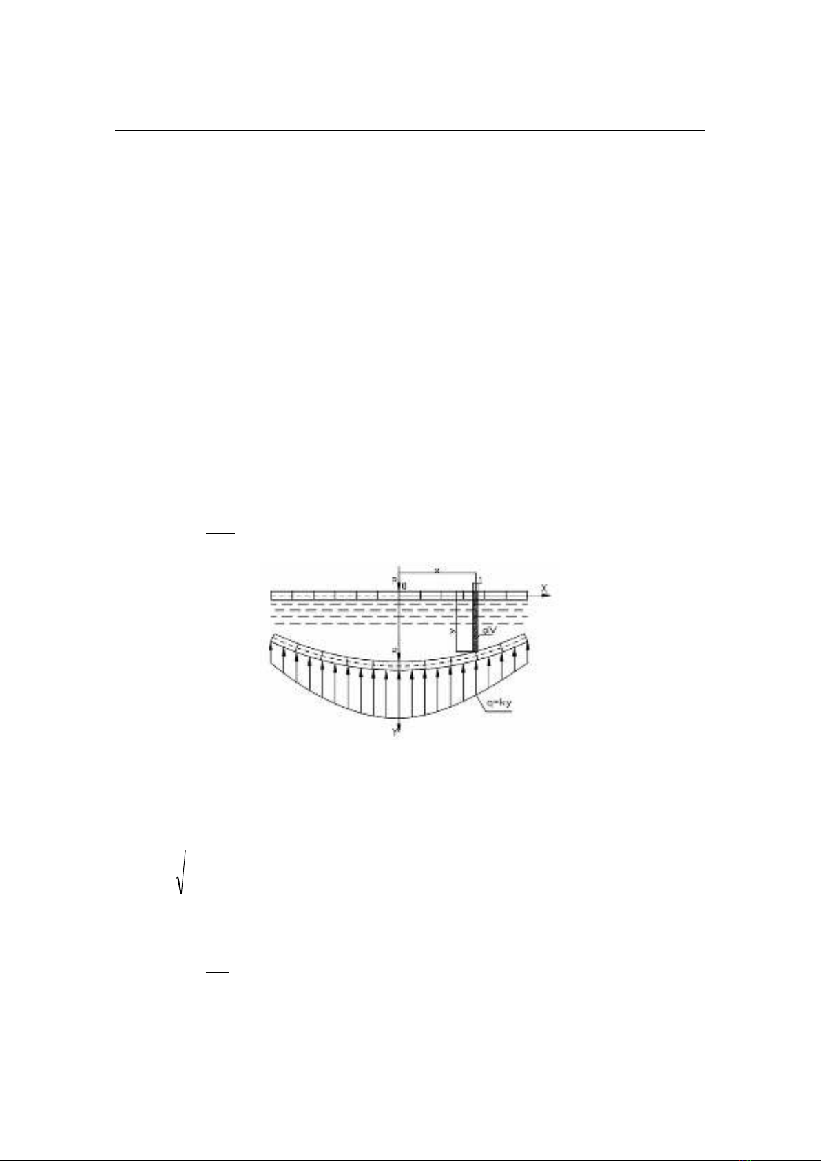
According to the analytical method [7-9]: Continuous floating bridges are
considered beams on an elastic foundation that is water. The calculation diagram is shown
in Fig. 2. When a concentrated load P (kN) is placed on a beam with stiffness EIz that is
placed on a uniform and isotropic elastic foundation. The beam will bend and sink into
the foundation. The foundation reaction force q (kN/m) has intensity distributed along the
length of the beam and is balanced with the load P. The intensity of the reaction force of
the ground q (kN/m) is proportional to the deformation of the ground y (m) at a certain
section, so
yKq
(1)
The proportionality coefficient K (kN/m2) (the model under consideration is a
2-dimensional plane problem, so the width of the beam is taken as 1m, K has dimensions
of kN/m2 because q has dimensions of kN/m; y has dimensions of m) is called the
foundation coefficient and it characterizes the elastic properties of the foundation, then:
q
dx
yd
EI z
4
4
(2)
Fig. 3. Calculation diagram of continuous floating bridge.
From formulas (1) and (2), the following is obtained:
0
4
4
yK
dx
yd
EI z
(3)
Set
44z
EI
K
(1/m), and solving Eq. (3) will obtain the equation representing the
elastic curve of the beam, consider the beam as infinitely long and the concentrated
force P = 1, then:
xexe
K
yxx
sincos
2
(4)
Section on Special Construction Engineering - Vol. 07, No. 02 (Dec. 2024)
86
For the problem of the floating bridge on water with an elastic foundation in
water, load per 1 m length
0
kN
; ( );
m
q B y q
or foundation coefficient
02
kN
; ( )
m
K B K
then:
0
4
444
zz
B
K
EI EI
(5)
where
is specific gravity of water,
0
B
(m) is width of the part in contact with the water
of the floating.
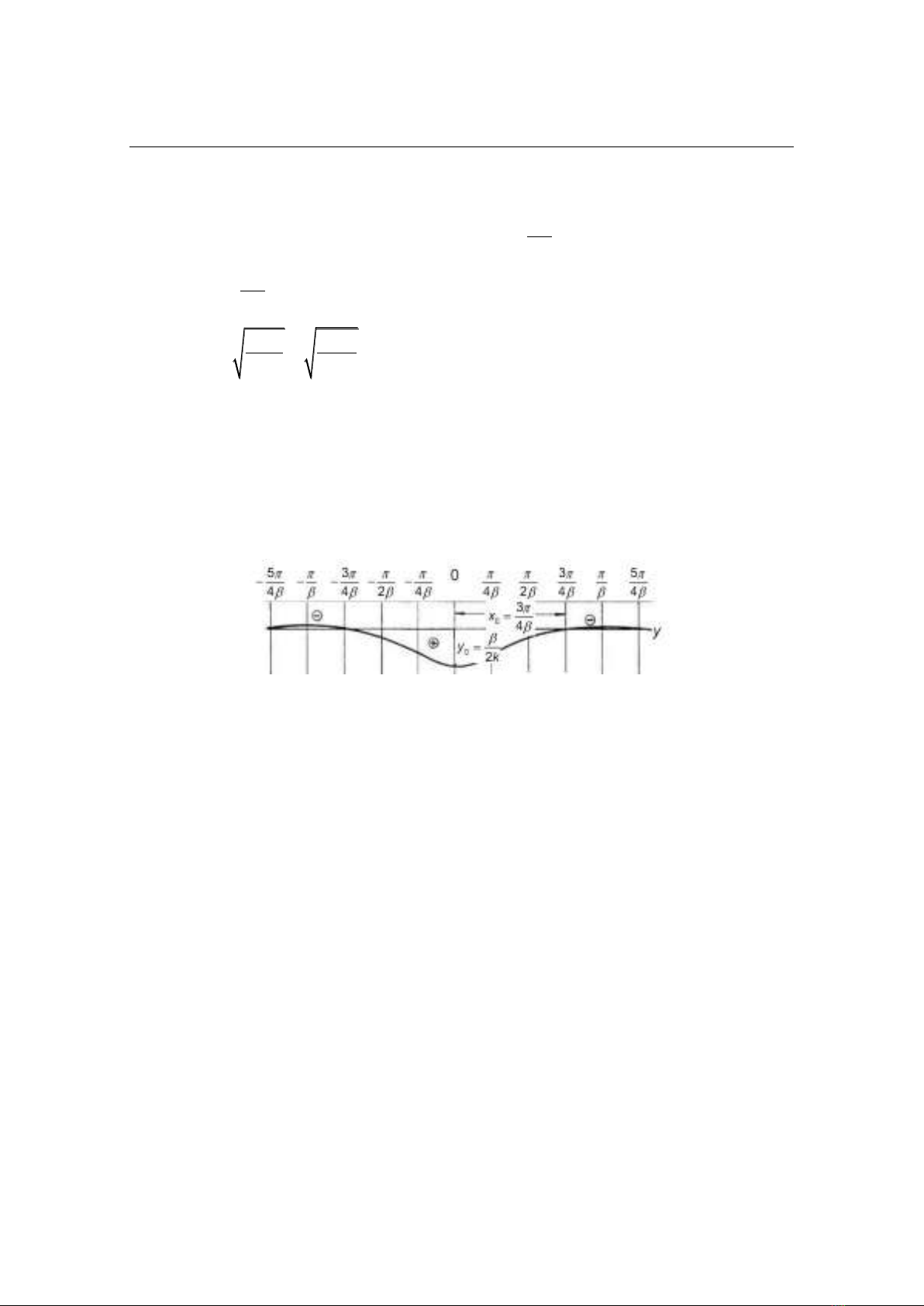
On the basis of the above formulas, the displacement influence line, also known as
the draft influence line, of the continuous floating bridge can be constructed as shown in
Fig. 4. Loading on the displacement (draft) influence line will result in the displacement
(draft) of the floating bridge when withstanded to load.
Fig. 4. Displacement influence line (water draft) of continuous floating bridge.
According to the finite element method using SAP2000 software [10, 11] is
summarized as follows:
In the finite element method, the continuous object is replaced by a finite number
of discrete elements. The basic steps of the finite element method include:
- Discretize the real structure into a pre-selected mesh of molecules suitable to the
geometric shape of the structure and the accuracy requirements of the problem. These
elements are connected by nodes.
- Build element properties.
- Build the element equilibrium equation [K]·{d} = {Q}.
in which [K] is element stiffness matrix, {d} is element's nodal displacement vector, {Q} is
nodal load vector. Representing the displacement at any point of the element through nodal
displacements {U} = [N]·{d} where [N] is coordinate function matrix (shape function).
- Calculate the element mass matrix.
- Calculate the resistance matrix.
Journal of Science and Technique - ISSN 1859-0209
87
- Build a general equilibrium equation from the element equations [K]·{r}= {P}.
- Solve the system of balanced equations to determine the nodal displacement of
the entire structure.
- From the found node displacement, determine each element.
While using finite elements, the floating bridge is placed directly on the water
surface so it can be considered an ideal one-coefficient beam model on an elastic
foundation. The water surface is replaced by a system of springs which is distributed at
the bottom of the buoys. The spring stiffness is determined from the background
coefficient. In SAP2000 software, elastic connections are described by spring bearings
located at the nodes.
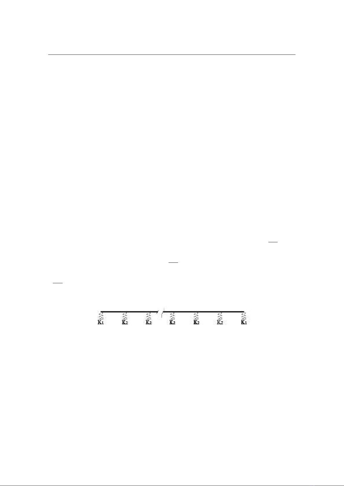
When calculating floating bridges, the stiffness of the spring depends on the area of
the elements in its zone of influence. The stiffness coefficient of a spring can be
determined by the product between the area of its influence zone and the background
coefficient. When calculating the middle section of the river, using the finite element
method with a finite bridge length, the spring stiffness coefficient will include two
coefficients:
1
K
- for the bridge head and bridge edge
1
kN
0.5 ( ),
m
K a b
and
2
K
- for the inner sections
2
kN
()
m
K a b
where
is specific gravity of water,
(
3
kN
m
), a is the distance between buoys vertically in the structure, (m), b is distance
between buoys horizontally across the structure, (m).
Fig. 5. Elastic bearing diagram when calculating the floating bridge.
2.3. Example of calculating the draft of a floating bridge assembled from plastic buoys
To better illustrate the method of determining the draft of an continuous floating
bridge assembled from plastic buoys, the authors chose a floating bridge with the
following dimensions: length
72(m)L
consists of a layer with 144 buoys that ensure
the length in the middle of the river, and width
3.5(m)B
that ensure one-way traffic,
the cross-section has a layer including 7 buoys as Fig. 6.


![Giáo trình Cấu trúc dữ liệu và giải thuật - Trường CĐ Cơ điện Hà Nội [Mới nhất]](https://cdn.tailieu.vn/images/document/thumbnail/2026/20260323/lionelmessi01/135x160/58171774381670.jpg)


![Giáo trình Tiện nâng cao (Nghề Cắt gọt kim loại, Trình độ Cao đẳng) - Trường Cao đẳng Cơ điện Hà Nội [Mới nhất]](https://cdn.tailieu.vn/images/document/thumbnail/2026/20260323/lionelmessi01/135x160/48101774403543.jpg)


