
472
ARDS = acute respiratory distress syndrome; ATC = automatic tube compensation; Ccw - chest wall compliance; Cl = lung compliance; COPD =
chronic obstructive pulmonary disease; CPAP = continuous positive airway pressure; Crs = respiratory system compliance; IPL = inspiratory pres-
sure level; LIP = lower inflection point; MIP = maximal inspiratory pressure; NIPPV = noninvasive positive pressure ventilation; Pavg = average inspira-
tory pressure; Paw = airway pressure; PEEP = positive end expiratory pressure; PEFR = peak expiratory flow rate; Pes = esophageal pressure; Pex =
end-expiratory pressure; Ps = inspiratory pressure; PTI = pressure time index; PTP = pressure time product; PV = pressure–volume curve; RSBI =
rapid shallow breathing index; SBT = spontaneous breathing trial; UIP = upper inflection point; Vt = tidal volume; WOB = work of breathing.
Critical Care October 2005 Vol 9 No 5 Grinnan and Truwit
Abstract
Pulmonary disease changes the physiology of the lungs, which
manifests as changes in respiratory mechanics. Therefore, measure-
ment of respiratory mechanics allows a clinician to monitor closely
the course of pulmonary disease. Here we review the principles of
respiratory mechanics and their clinical applications. These
principles include compliance, elastance, resistance, impedance,
flow, and work of breathing. We discuss these principles in normal
conditions and in disease states. As the severity of pulmonary
disease increases, mechanical ventilation can become necessary.
We discuss the use of pressure–volume curves in assisting with
poorly compliant lungs while on mechanical ventilation. In addition,
we discuss physiologic parameters that assist with ventilator
weaning as the disease process abates.
Introduction
In humans ventilation involves movement of the chest wall to
produce a pressure gradient that will permit flow and movement
of gas. This can be accomplished by the respiratory muscles, by
negative pressure ventilation (iron lung), or by positive pressure
ventilation (mechanical ventilator). Measurements of respiratory
mechanics allow a clinician to monitor closely the course of
pulmonary disease. At the bedside, changes in these mechanics
can occur abruptly (and prompt immediate action) or they may
reveal slow trends in respiratory condition (and prompt initiation
or discontinuation of mechanical ventilation). Here we focus on
the mechanical measurements that can be used to help make
clinical decisions.
Compliance
In respiratory physiology, lung compliance describes the
willingness of the lungs to distend, and elastance the willing-
ness to return to the resting position. Compliance is deter-
mined by the following equation: C = ∆V/∆P, where C is
compliance, ∆V is change in volume, and ∆P is change in
pressure. The inverse of compliance is elastance (E ~ 1/C).
Airway pressure during inflation is influenced by volume,
thoracic (lung and chest wall) compliance, and thoracic
resistance to flow. Resistance to flow must be eliminated if
compliance is to be measured accurately. This is
accomplished by measuring pressure and volume during a
period of zero flow, termed static measurements. Therefore,
compliance is determined by taking static measurements of
the distending pressure at different lung volumes and can be
done during inflation or deflation [1]. Plotting pressure
measurements throughout the respiratory cycle allows a
pressure–volume (PV) curve to be constructed (Fig. 1).
The slope of this curve is equal to the compliance. The
inspiratory and expiratory curves are separated on the PV
curve; this area of separation is termed hysteresis. Hysteresis
develops in elastic structures when the volume change from
an applied force is sustained for some time after the force is
removed [2]. In the lungs, hysteresis results both from the
collapse of small airways and from the surface tension at the
gas–liquid interface of alveoli that must be overcome to
inflate the lungs. The degree of hysteresis is greater when a
breath is initiated near the residual volume and less when it is
initiated at higher lung volumes [2]. Both the chest wall and
the lung influence respiratory compliance. The total thoracic
compliance is less than individual compliances of the chest or
lung because the two add in parallel (elastances, the inverse,
add in series) [3]: Crs = Ccw × Cl/(Ccw + Cl), where Crs,
Ccw, and Cl are the compliances of the respiratory system,
chest wall, and lung, respectively (Fig. 2 and Table 1).
Review
Clinical review: Respiratory mechanics in spontaneous and
assisted ventilation
Daniel C Grinnan1and Jonathon Dean Truwit2
1Fellow, Department of Pulmonary and Critical Care, University of Virginia Health System, Virginia, USA
2E Cato Drash Professor of Medicine, Senior Associate Dean for Clinical Affairs, Chief, Department of Pulmonary and Critical Care, University of
Virginia Health System, Virginia, USA
Corresponding author: Daniel C Grinnan, dg6j@virginia.edu
Published online: 18 April 2005 Critical Care 2005, 9:472-484 (DOI 10.1186/cc3516)
This article is online at http://ccforum.com/content/9/5/472
© 2005 BioMed Central Ltd

473
Available online http://ccforum.com/content/9/5/472
Reduced compliance can be caused by a stiff chest wall or
lungs, or both. The distinction can be clinically significant. To
separate the contribution made by each to total lung
compliance, a measure of intrapleural pressure is needed.
The most accurate surrogate marker for intrapleural pressure
is esophageal pressure, which can be measured by placing
an esophageal balloon [1]. However, this is rarely done in
clinical practice. Alternatively, changes in central venous
pressure can approximate changes in esophageal pressure,
but this technique is yet to be verified [1].
Respiratory system compliance is routinely recorded at the
bedside of critically ill patients. In mechanically ventilated
patients, this is done by measuring end-expiratory alveolar
pressure (Pex) and end-inspiratory alveolar pressure (also
called peak static or plateau pressure [Ps]), so that the
change in volume is the tidal volume (Vt). Alveolar pressure
can easily be assessed after occlusion of the airway, because
the pressure in the airway equilibrates with alveolar pressure.
Pex is the pressure associated with alveolar distention at the
end of a breath. In normal individuals this is usually zero when
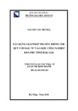
Figure 1
Pressure–volume curve. Shown is a pressure–volume curve developed from
measurements in isolated lung during inflation (inspiration) and deflation
(expiration). The slope of each curve is the compliance. The difference in the
curves is hysteresis. Reprinted from [3] with permission from Elsevier.
Figure 2
Compliance of the lungs, chest wall, and the combined lung–chest
wall system. At the functional residual capacity, the forces of
expansion and collapse are in equilibrium. Reprinted from [3] with
permission from Elsevier.
Table 1
Causes of decreased intrathoracic compliance
Causes of decreased measured chest wall compliance Causes of decreased measured lung compliance
Obesity Tension pneumothorax
Ascites Mainstem intubation
Neuromuscular weakness (Guillain–Barre, steroid myopathy, etc.) Dynamic hyperinflation
Flail chest (mediastinal removal) Pulmonary edema
Kyphoscoliosis Pulmonary fibrosis
Fibrothorax Acute respiratory distress syndrome
Pectus excavatum Langerhans cell histiocytosis
Chest wall tumor Hypersensitivity pneumonitis
Paralysis Connective tissue disorders
Scleroderma Sarcoidosis
Cryptogenic organizing pneumonitis
Lymphangitic spread of tumor
Shown are the causes of decreased intrathoracic compliance, partitioned into causes of decreased measured chest wall compliance and causes of
decreased measured lung compliance.

474
Critical Care October 2005 Vol 9 No 5 Grinnan and Truwit
referenced to atmosphere. However, when positive end-
expiratory pressure (PEEP) is applied, Pex is at least as great
as PEEP. It may be greater if air trapping occurs, and the
associated pressure beyond PEEP is termed auto-PEEP or
intrinsic PEEP. The clinician will need to know Ps, Pex, auto-
PEEP, and Vt to determine respiratory compliance at the
bedside. For example, if the PEEP is 5 cmH2O, auto-PEEP is
0 cmH2O, Ps is 25 cmH2O, and Vt is 0.5 l, then Crs = ∆V/∆P
= 0.5 l/(25 – 5) = 0.5/20 = 0.025 l/cmH2O or 25 ml/cmH2O.
In a normal subject on mechanical ventilation, compliance
should be greater than 50–100 ml/cmH2O [4].
Patients with obstructive lung disease have a prolonged
expiratory phase. At baseline, most patients with emphysema
have increased compliance (because of decreased elastance
of the lungs). If the Vt is not completely exhaled, then a
certain amount of air will be ‘trapped’ in the alveoli. If this
continues over several breaths, then it will result in ‘stacking’
of breaths until a new end-expiratory thoracic volume is
achieved. As the volume increases (dynamic hyperinflation),
the functional residual capacity will be increased. As a result,
tidal breathing will occur at a less compliant portion of the PV
curve (Fig. 3).
The pressure difference associated with the trapped volume
is called auto-PEEP. Caution must be used in a patient who
has obstructive lung disease and is on mechanical ventilation.
Usually, such patients are treated aggressively for airway
inflammation (bronchodilator treatments and corticosteroids),
while the respiratory rate is decreased and the expiratory
phase of respiration is prolonged. If the functional residual
capacity is increased, delivering the same Vt may increase
the transalveolar pressure, which can impede venous return
(resulting in hypotension) or lead to a pneumothorax. The
development of hypotension in a patient with dynamic
hyperinflation should prompt the clinician to listen to the
lungs and assess the ventilator for auto-PEEP. If auto-PEEP is
suspected, then the patient should be disconnected from the
ventilator to determine whether the hypotension resolves
when delivered breaths are withheld (Fig. 4).
Auto-PEEP can be measured in patients on mechanical
ventilators by creating an end-expiratory pause. The end-
expiratory pause maneuver allows the pressure transducer of
the ventilator to approximate the end-expiratory alveolar
pressure, or auto-PEEP. Some ventilators allow the clinician
to create and control the expiratory pause, whereas other
ventilators perform an end-expiratory pause as an automated
function that requires only the push of a button. Measure-
ments of auto-PEEP require a passive patient because
patient interaction in breathing will alter the measurements of
the pressure transducer. In the intensive care unit, this usually
requires sedation and, occasionally, paralysis.
Decreasing the amount of auto-PEEP on mechanical
ventilation requires one to decrease the respiratory rate and
prolong the expiratory phase of ventilation. Execution of these
goals often requires eliminating patient effort through heavy
sedation or paralysis. Once patient effort is eliminated, it is
important to follow respiratory mechanics closely, including
auto-PEEP and compliance. In order to protect the lungs from
barotrauma, it is common to permit a certain amount of
hypoventilation, termed permissive hypercapnia. Permissive
hypercapnia has been proven safe and allows a clinician to
use the lowest respiratory rate and Vt possible, thus
protecting the lungs while they are impaired.
Patients with auto-PEEP (or intrinsic PEEP) who require
mechanical ventilation are often asynchronous with the
ventilator. During assisted modes of ventilation, patients with
auto-PEEP often have difficulty triggering the ventilator to
initiate a breath. The patient must first overcome the auto-
PEEP before creating the negative intrapleural pressure
required to trigger the ventilator. The patient can be assisted
by applying extrinsic PEEP, of a magnitude less than Pex, to
the circuit. Now the pressure needed to be generated by the
Figure 3
Compliance in emphysema and fibrosis. Shown are changes in the compliance of the inspiratory limb of the pressure–volume curve with respect to
(a) chest wall, (b) lungs, and (c) combined lung-chest wall system in patients with emphysema and fibrosis. The functional residual capacity (FRC),
represented on the vertical axis at a transmural pressure of 0, is elevated in emphysema, which can lead to dynamic hyperinflation. Reprinted from
[3] with permission from Elsevier.

475
patient to trigger the ventilator is decreased because the
trigger sensitivity of the ventilator is centered around the
applied extrinsic PEEP and not atmospheric pressure.
Therefore, more patient initiated efforts will be able to trigger
the ventilator successfully.
Acute respiratory distress syndrome (ARDS) is a common
condition in the intensive care unit and is characterized by low
compliance. Typically, the start of inspiration occurs at low
volumes (near the residual volume) and requires high pressure
to overcome surface tension and inflate the alveoli. The
relation between pressure and surface tension is explained by
Laplace’s Law, which relates pressure to radius in spherical
structures: P = 2T/r, where P = pressure, T = surface tension,
and r = radius. Below we discuss the role of PV curves in
patients with ARDS who require mechanical ventilation.
Pressure–volume curves and ventilator
management in ARDS
The PV curve of the lung and chest wall is obtained by
plotting the corresponding pressure at different Vts. As
mentioned previously, the resulting slope is the compliance of
the lung and chest wall. In recent years, much interest has
centered on using the PV curve to help select the optimal
ventilator settings for patients on mechanical ventilation.
Patients with ARDS on mechanical ventilation have been the
focus of this attention.
There are various ways to measure the PV curve in patients
on mechanical ventilation. Each method has advantages and
disadvantages [5]. Some methods require specialized
equipment that is not available in all intensive care units. With
the syringe technique, the patient is removed from the
mechanical ventilator and a 2 l syringe is placed on the endo-
tracheal tube. Increments of 50–150 cc of 100% oxygen are
delivered, and a transducer measures the corresponding
airway pressure at each volume [2]. These values are then
plotted and connected to form the PV curve. An alternative
approach is to use the multiple occlusion technique. With this
method, the patient remains on the ventilator. The plateau
pressure is measured at different Vts (ranging from 200 cc to
1300 cc) and plotted to form the PV curve. It is important to
allow several breaths at a standard volume between
measurements to obtain the most accurate result. A recent
study [5] showed that the multiple occlusion technique and
the syringe technique yield similar measurements. A third
approach is the continuous low-flow technique. Maintaining a
low inspiratory flow rate on the mechanical ventilator (less
than 10 l/min) minimizes resistance, permitting estimation of
the PV curve [2]. All methods used to obtain a PV curve
generally require a passive patient for accurate results. The
risks associated with sedation and paralysis (which may be
needed) should be considered before proceeding to create a
PV curve.
The PV curve will change with time and with differences in
pressure [5]. In ARDS, the PV curve will change as the
disease progresses or resolves [6]. In the early (exudative)
stage, the PV curve generally exhibits low compliance and a
well demarcated lower inflection point (LIP). As the disease
progresses (fibrotic stage), the compliance remains low but
the LIP is obscured [2]. ARDS is also associated with a
rapidly changing clinical course. The shape of a PV curve may
change over several hours in the same patient. Therefore, up-
to-date measurements are needed before ventilator settings
are manipulated, if one is relying upon the PV curve.
Traditionally, the PV curve has been calculated with zero end-
expiratory pressure [7-9]. When calculated with different
levels of PEEP, the PV curve will be altered [8,9]. In addition,
the ventilator mode and level of ventilation that a patient is on
before calculation of a PV curve can affect the shape of the
curve [9]. These drawbacks make it difficult to know whether
PV curves may be relied upon for bedside use (Fig. 5).
The inspiratory phase of the PV curve consists of three
sections. The first section occurs at a low volume, and is
nonlinear and relatively flat (low compliance). As the volume
increases, the second section of the curve is linear and has a
steeper slope (higher compliance). The third section of the
curve is again nonlinear and flat (return to low compliance).
The junction between the first and second portion of the
curve is called the LIP. The LIP can be calculated by inter-
secting the lines from the first and second portions of the
curve. Alternatively, the LIP can be calculated by measuring
the steepest point of the second section and then marking
the LIP as the point of a 20% decrease in slope from this
steepest point. Studies assessing interobserver reliability
have varied. Some have found good interobserver variability,
whereas others have found significant variability [2,5,7]. The
junction of the second and third portions of the curve is
Available online http://ccforum.com/content/9/5/472
Figure 4
Ventilator tracing with a square wave, or constant flow, pattern. Note
that the machine is triggered to initiate a breath before flow returns to
zero (the horizontal axis). This indicates that auto-PEEP (positive end-
expiratory pressure) is present and directs the clinician to investigate
further.

476
called the upper inflection point (UIP). The UIP can be
measured in the same way as the LIP (except the UIP would
represent a 20% increase from the point of the greatest
slope). Studies have generally found that there is good
interobserver agreement and good agreement between
methods for measuring UIP [5,10].
The LIP and UIP are points that represent changes in
compliance. In the past, the LIP was thought to represent the
end of alveolar recruitment. The opening of an alveolus during
inspiration was thought to cause shear stress that would be
harmful to the lung. Therefore, by setting the amount of PEEP
above the LIP, the level of shear stress could be decreased
[11,12]. The UIP was thought to represent the start of
alveolar overdistension. It was thought that if the airway
pressure exceeded the UIP, then harmful alveolar stretch and
overdistension would occur [11,12]. In keeping the level of
PEEP above the LIP and the plateau pressure below the UIP,
the patient would receive Vts at the most compliant part of
the PV curve. By following the PV curve over time, the
ventilator settings could be individually tailored to provide the
maximal benefit and the minimal damage to the patient with
ARDS requiring mechanical ventilation.
In 1999, Amato and coworkers [11] reported the results of a
prospective, randomized, controlled trial using the PV curve
as a guide to ventilation. The level of PEEP was maintained at
2 cmH2O above the LIP in the experimental group, with a
plateau pressure of 20 cmH2O or less. When compared with
‘conventional ventilation’ (use of lower PEEP, higher Vts, and
higher plateau pressures), there was a significant difference
in mortality at 28 days (38% versus 71%) and a significant
difference in the rate of weaning favoring the experimental
group. This study supported the clinical practice of setting
the PEEP at 2 cmH2O above the LIP. However, because the
plateau pressure was also manipulated, it is difficult to attribute
the mortality difference to PEEP. Moreover, the mortality rate in
the control group was higher than expected, because other
studies conducted in ARDS patients have consistently found
mortality rates around 40% in control arms [13].
It is now apparent that alveoli are recruited throughout the
inspiratory limb of the PV curve (not just below the LIP, as
was previously assumed) [14,15]. We now believe that the
LIP represents a level of airway pressure that leads to
increased recruitment of alveoli. This increased recruitment is
sustained throughout the second portion of the PV curve and
is reflected by a steep slope, indicating increased
compliance. The UIP, in turn, represents a point of decreased
alveolar recruitment. Recruitment of alveoli on inspiration
begins in the nondependent portion of the lungs and slowly
spreads to the dependent portion of the lungs [16]. Areas of
atelectasis may require inspiratory pressures above
40 cmH2O before alveoli will be recruited [16]. Clearly, in this
model of the PV curve, setting the PEEP above the LIP will
not reduce shear stress by starting inspiration after alveolar
recruitment.
The model of continuous recruitment also dissociates the LIP
from PEEP [16]. Previously, when the LIP was thought to
represent the completion of alveolar recruitment, the PEEP
that corresponded to the LIP was thought to sustain alveolar
recruitment and prevent alveolar shear stress. However,
because alveoli are continually recruited along the inspiratory
limb of the PV curve, the ‘optimal PEEP’ may be difficult to
determine from the inspiratory limb. Moreover, PEEP is an
expiratory phenomenon, and it corresponds to pressures on
the expiratory curve rather than the inspiratory curve [17].
Because hysteresis exists between the inspiratory and
expiratory limbs, it is difficult to estimate the effect that PEEP
will have on the inspiratory curve [17,18].
Clinical studies attempting to improve outcomes in ARDS by
varying levels of PEEP have had disappointing results. In
2004 the ARDS Network investigators [19] reported a
prospective study comparing the effects of lower PEEP
(mean 8–9 cmH2O) with those of higher PEEP (mean
13–15 cmH2O). The results did not reveal a significant
difference in clinical outcomes (mortality, time of ICU stay,
time on mechanical ventilator) between the two groups. In
that study, the LIP was not used to guide the ‘high PEEP’
group as had been done in the study conducted by Amato
and coworkers. A weakness of the study was that the level of
PEEP used in the ‘high PEEP’ group was changed during the
study, potentially altering the outcome [20].
Clinical research has proven that large Vts are detrimental in
ARDS. In 2000, findings were reported by the ARDS
Network investigators [21]. In that prospective, randomized,
Critical Care October 2005 Vol 9 No 5 Grinnan and Truwit
Figure 5
The inspiratory limb of the pressure–volume curve (dark line) divided
into three sections. Section 1 (low compliance) and section 2 (high
compliance) are separated by the lower inflection point (LIP). Section
2 (high compliance) and section 3 (low compliance) are separated by
the upper inflection point (UIP). In this example, the LIP is marked at
the point of crossing of the greatest slope in section 2 and the lowest
slope of section 1. The UIP is marked at the point of 20% decrease
from the greatest slope of section 2 (a calculated value).


![PET/CT trong ung thư phổi: Báo cáo [Năm]](https://cdn.tailieu.vn/images/document/thumbnail/2024/20240705/sanhobien01/135x160/8121720150427.jpg)


%20--%3e%3cdefs%3e%3cstyle%3e%20.st0%20{%20fill:%20%23fff;%20}%20.st1%20{%20fill:%20%237800fa;%20}%20%3c/style%3e%3c/defs%3e%3cpath%20class='st1'%20d='M117.78,12.18H43.11c2.9,3.47,4.65,7.94,4.65,12.82,0,5.6-2.3,10.66-6.01,14.29h76.02l7.22-13.56-7.22-13.56Z'/%3e%3cg%3e%3cpath%20class='st0'%20d='M53.58,26.17h-.59v-1.46h.59v-4.96h2.83c1.78,0,2.67.94,2.67,2.82v5.76c0,1.87-.89,2.81-2.67,2.81h-2.83v-4.96ZM55.36,21.37v3.34h1.1v1.46h-1.1v3.34h1.01c.61,0,.91-.37.91-1.1v-5.93c0-.74-.3-1.1-.91-1.1h-1.01Z'/%3e%3cpath%20class='st0'%20d='M65.99,31.14h-1.8l-.31-2.07h-2.19l-.31,2.07h-1.64l1.82-11.39h2.62l1.82,11.39ZM65.28,18.04c-.25.46-.51.77-.75.94-.21.15-.47.22-.79.22-.26,0-.57-.07-.92-.22l-.38-.15c-.14-.05-.26-.07-.37-.07-.3,0-.53.18-.71.54l-.91-.68c.25-.46.51-.77.75-.94.21-.14.48-.21.79-.21.26,0,.57.07.92.21l.38.15c.14.05.26.07.37.07.3,0,.53-.18.71-.54l.91.68ZM61.91,27.52h1.73l-.87-5.76-.87,5.76Z'/%3e%3cpath%20class='st0'%20d='M74.53,26.89v1.52c0,1.91-.89,2.86-2.67,2.86s-2.67-.95-2.67-2.86v-5.93c0-1.91.89-2.86,2.67-2.86s2.67.95,2.67,2.86v1.11h-1.69v-1.22c0-.75-.31-1.12-.93-1.12s-.93.37-.93,1.12v6.15c0,.74.31,1.11.93,1.11s.93-.37.93-1.11v-1.63h1.69Z'/%3e%3cpath%20class='st0'%20d='M81.4,31.14h-1.8l-.31-2.07h-2.19l-.31,2.07h-1.64l1.82-11.39h2.62l1.82,11.39ZM75.9,19.2l1.52-1.91h1.71l1.51,1.91h-1.61l-.76-.95-.75.95h-1.61ZM77.32,27.52h1.73l-.87-5.76-.87,5.76ZM83.1,15.99l-1.76,1.91h-1.26l1.17-1.91h1.86Z'/%3e%3cpath%20class='st0'%20d='M84.86,19.75c1.78,0,2.67.94,2.67,2.82v1.48c0,1.87-.89,2.81-2.67,2.81h-.85v4.28h-1.79v-11.39h2.64ZM84.01,21.37v3.86h.85c.58,0,.87-.36.87-1.08v-1.71c0-.71-.29-1.07-.87-1.07h-.85Z'/%3e%3cpath%20class='st0'%20d='M93.51,19.75c1.78,0,2.67.94,2.67,2.82v1.48c0,1.87-.89,2.81-2.67,2.81h-.85v4.28h-1.79v-11.39h2.64ZM92.66,21.37v3.86h.85c.58,0,.87-.36.87-1.08v-1.71c0-.71-.29-1.07-.87-1.07h-.85Z'/%3e%3cpath%20class='st0'%20d='M98.8,31.14h-1.79v-11.39h1.79v4.88h2.03v-4.88h1.83v11.39h-1.83v-4.88h-2.03v4.88Z'/%3e%3cpath%20class='st0'%20d='M105.36,24.55h2.46v1.62h-2.46v3.34h3.09v1.63h-4.88v-11.39h4.88v1.63h-3.09v3.18ZM108.17,17.29l-1.76,1.91h-1.26l1.17-1.91h1.86Z'/%3e%3cpath%20class='st0'%20d='M112.2,19.75c1.78,0,2.67.94,2.67,2.82v1.48c0,1.87-.89,2.81-2.67,2.81h-.85v4.28h-1.79v-11.39h2.64ZM111.35,21.37v3.86h.85c.58,0,.87-.36.87-1.08v-1.71c0-.71-.29-1.07-.87-1.07h-.85Z'/%3e%3c/g%3e%3ccircle%20class='st1'%20cx='25'%20cy='25'%20r='20'/%3e%3cpath%20class='st0'%20d='M32.78,19.27c2.92,0,4.43,2.55,5.28,5.33l.71,2.17c.14.38-.33.75-.71.75h-5.61c.19-.33.24-.71.09-1.08l-.75-2.45c-.43-1.32-.99-2.64-1.79-3.77.75-.57,1.65-.94,2.78-.94h0ZM25,18.38c3.25,0,4.9,2.78,5.89,5.89l.76,2.45c.14.42-.33.8-.8.8h-11.69c-.42,0-.94-.38-.8-.8l.75-2.45c.99-3.11,2.64-5.89,5.89-5.89h0ZM25,11.35c1.74,0,3.11,1.37,3.11,3.11s-1.37,3.11-3.11,3.11-3.11-1.41-3.11-3.11,1.41-3.11,3.11-3.11h0ZM17.27,19.27c1.08,0,1.98.38,2.73.94-.8,1.13-1.37,2.45-1.74,3.77l-.8,2.45c-.14.38-.05.75.09,1.08h-5.56c-.42,0-.9-.38-.75-.75l.71-2.17c.9-2.78,2.41-5.33,5.33-5.33h0ZM17.27,12.91c1.51,0,2.78,1.27,2.78,2.83s-1.27,2.83-2.78,2.83-2.83-1.27-2.83-2.83,1.27-2.83,2.83-2.83h0ZM32.78,12.91c1.56,0,2.78,1.27,2.78,2.83s-1.23,2.83-2.78,2.83-2.83-1.27-2.83-2.83,1.27-2.83,2.83-2.83h0ZM27.07,28.56v.09c0,.57-.24,1.08-.61,1.46h0v.05c-.38.33-.9.57-1.46.57s-1.08-.24-1.46-.61h0c-.38-.38-.61-.9-.61-1.46v-.09h1.41v.09c0,.19.05.38.19.47v.05c.09.09.28.19.47.19s.38-.09.47-.19v-.05c.14-.09.24-.28.24-.47t-.05-.09h1.41ZM30.99,28.56v.09c0,1.65-.66,3.16-1.74,4.24-1.08,1.08-2.59,1.79-4.24,1.79s-3.16-.71-4.24-1.79l-.05-.05c-1.04-1.08-1.7-2.55-1.7-4.2v-.09h1.41v.09c0,1.27.47,2.4,1.27,3.25h.05c.85.85,1.98,1.37,3.25,1.37s2.4-.52,3.25-1.37c.85-.8,1.37-1.98,1.37-3.25v-.09h1.37ZM34.99,28.56v.09c0,2.78-1.13,5.28-2.92,7.07-1.79,1.79-4.29,2.92-7.07,2.92s-5.23-1.13-7.07-2.92c-1.79-1.79-2.92-4.29-2.92-7.07v-.09h1.41v.09c0,2.4.94,4.53,2.5,6.08,1.56,1.56,3.72,2.5,6.08,2.5s4.52-.94,6.08-2.5c1.56-1.56,2.5-3.68,2.5-6.08v-.09h1.41Z'/%3e%3c/svg%3e)