
REGULAR ARTICLE
Cooling the intact loop of primary heat transport system using
Shutdown Cooling System in case of LOCA events
Diana Laura Icleanu
*
, Ilie Prisecaru, and Iulia Nicoleta Jianu
Polytechnic University of Bucharest, Splaiul Independentei, nr. 313, Bucharest, 060042, Romania
Received: 6 May 2015 / Received in final form: 22 September 2015 / Accepted: 14 October 2015
Published online: 11 December 2015
Abstract. The purpose of this paper is to model the operation of the Shutdown Cooling System (SDCS) for
CANDU 6 nuclear power plants in case of LOCA accidents, using Flowmaster calculation code, by delimiting
models and setting calculation assumptions, input data for hydraulic analysis and input data for calculating
thermal performance check for heat exchangers that are part of this system.
1 Introduction
Power and energy industries have their unique challenges
but they all need to rely on the efficient running of their
piping systems and, therefore, optimum design and
continual effective maintenance are essential. The ability
to ensure accurate delivery of a product and raw materials,
especially over long distances and significant elevation
changes, is vital to the overall operation and success of a
process plant. For such analysis, Flowmaster is a useful
code. This code has been applied for analyzing the systems
of CANDU reactors due to the user’s possibility of defining
the incompressible and compressible fluids and also the
solid materials based on thermodynamic and thermo-
physical properties of these materials [1] stored in the
corresponding generic database of the program.
Considering this, the following paper has analyzed the
failure operation modes in case of loss of coolant accidents
(LOCA), described in the design documentation.
The first chapter of the study provides an overview of
the Shutdown Cooling System (SDCS) and an overview of
the operating regimes of the system. In this section, general
considerations and aspects of nuclear safety related to the
LOCA accidents are also presented.
Furthermore, modeling the operation of the SDCS is
performed using Flowmaster [2], by delimiting the models
and developing supportable computing assumptions of the
geometric configuration. It also requires introducing the
input data and the calculation assumptions for the
hydraulic analysis and for the thermal calculation in order
to verify the functioning of the heat exchangers that are
part of this system.
Abnormal operating conditions [3] for the SDCS were
analyzed using Flowmaster [4] calculation code and a
comparison of the results was made with data obtained
from a series of models developed in Pipenet.
From the results of the thermal-hydraulic analysis and
the comparison with data from the compilings performed
with Pipenet, it was found that in all operating conditions
of the system, in case of a LOCA type accident,
performance requirements specified in the design documen-
tation are confirmed by the analysis. After modeling the
SDCS, its functionality was demonstrated by achieving the
required performance.
2 Overview of the Shutdown Cooling System
and the computer code used for analysis
The SDCS is provided for cooling the Primary Heat
Transport System (PHTS) from 177 °Cto54°C and
holding the system at 54 °C for an indefinite period of time.
During normal operation with the reactor at power, the
SDCS is kept full with heavy water at 38 °C (100 °F)
temperature and a pressure equal to or just above
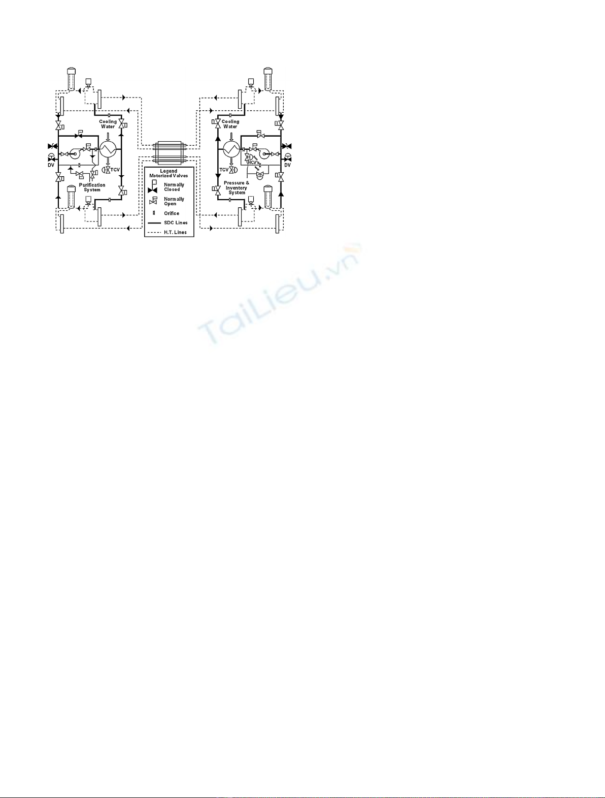
atmospheric pressure. Figure 1 reveals the simplified network
of the SDCS coupled with the PHTS in normal operation.
There are two cool down options available. The initial
phase of both options is similar and involves the use of the
CSDVs (Condenser Steam Discharge Valves) to lower the
PHTS temperature from 260 °C, at the rate of 2.8 °C/min.
During this phase, the PHTS pumps circulate the coolant
through the steam generators. If the SDCS pumps are to be
used in the next cool down phase, the PHTS temperature
first has to be brought down to 149 °C by means of the
CSDVs. Cool down to 54 °C at the rate of 2.8 °C/min is
*e-mail: icleanud@router.citon.ro
EPJ Nuclear Sci. Technol. 1, 13 (2015)
©D.L. Icleanu et al., published by EDP Sciences, 2015
DOI: 10.1051/epjn/e2015-50024-y
Nuclear
Sciences
& Technologies
Available online at:
http://www.epj-n.org
This is an Open Access article distributed under the terms of the Creative Commons Attribution License (http://creativecommons.org/licenses/by/4.0),
which permits unrestricted use, distribution, and reproduction in any medium, provided the original work is properly cited.
carried out using the SDCS pumps and heat exchangers
(HX).
2.1 Operating the SDCS in case of LOCA
Following a large LOCA, with or without Class IV power,
the SDCS is required to cool the PHTS intact loop. For the
first 900 seconds (15 minutes), upon receipt of the LOCA
signal, the Moderator Temperature Control (MTC)
program controls the “moderator rapid cool down”.
Following the first 900 seconds after LOCA, the recircu-
lated cooling water flow rate of 200 L/s is made available to
the SDCS by limiting the opening of the large temperature
control valves (an MTC program action) to limit the flow
towards the heat exchangers.
In this case, in order to cool down the PHTS intact loop,
the operator has to bring in the SDCS manually, following a
large LOCA, which will act as a backup heat sink for the
thermo-siphoning of the intact loop [5].
This paper analyses the case of cooling the intact loop of
the PHTS, using the SDCS, 15 or 30 minutes after the
initiation of LOCA, using both the pumps and the heat
exchangers of the SDCS or only one pump and one heat
exchanger (Class IV or Class III available) [6].
LOCA [7] are the most severe challenges for all security
systems, requiring that they operate at the best perfor-
mance levels.
2.2 Fundamentals in Flowmaster
For the development of the thermal-hydraulic analysis of
the SDCS, the computing program Flowmaster was used, a
one-dimensional thermal-hydraulic calculation code for
dimensioning, analyzing and verifying the operation of the
pipeline systems.
This code provides a graphical virtual working
environment and enables the design, redefinition and test
of the whole fluid flow system.
Steady state or transient modules of Flowmaster code
for single-phase fluids were designed specifically in order to
model the heat transfer effects in many application areas.
The modules enable users to develop transient analysis for
such kind of events.
Each component of Flowmaster is a mathematical
model for a piece of equipment that is included in a
facility.
Selected components are connected via nodes in order to
form a network which constitutes a computerized model of
the system.
A Flowmaster network contains a number of compo-
nents (pipes, tubing, pumps, fans, flow and pressure
sources, etc.) and the links between them.
The points in which components are linked to one
another are called nodes.
When a network is prepared for simulation, each
component and node must have a unique label. Filling the
entire schematic representation (Flowmaster network) is
an essential part of any simulation.
The nodal diagram (Flowmaster network) achieved
consisted of a sequence of segments separated by nodes,
which represent portions of pipe trails sections, without
diameter or branch variations along them. Various equip-
ments or components (except for retaining tabs) are
represented by pressure loss coefficients.
For simulating using Flowmaster code, the heavy water
flow in the SDCS in order to determine the variation of
pressure and flow at various points of the circuit, a nodal
scheme –Flowmaster network was done.
The Flowmaster computing code [8] was verified with
an exact calculation on the thermal part of the analysis and
with Pipenet program on the hydraulic part of it.
3 Application of Flowmaster code in thermal-
hydraulic analysis of the SDCS
3.1 Models and computing hypotheses
In order to develop the thermal-hydraulic analysis of
the SDCS in case of LOCA, the following calculation
models that cover the requirements of the design theme
were done.
3.1.1 Model I
Hydraulic calculation model for the SDCS, when operating
under a LOCA failure mode, model in which the cooling of
the PHTS is started at 177 °C using heat exchangers, HX1
and HX2, to provide the cold source, while the circulation
will be maintained by the SDCS pumps, P1 and P2.
3.1.2 Model II
Hydraulic calculation model for the SDCS, when operating
under a LOCA failure mode, model in which the cooling of
the PHTS is started at 177 °C using one heat exchanger, HX1
or HX2, to provide the cold source, while the circulation will
be maintained by one of the SDCS pumps, P1 or P2.
Fig. 1. Simplified network of SDCS coupled with PHTS. (Source:
https://canteach.candu.org/Content%20Library/19930204.pdf).
2 D.L. Icleanu et al.: EPJ Nuclear Sci. Technol. 1, 13 (2015)

3.1.3 Model III
Thermal calculation model for the heat exchangers, HX1
and HX2, related to the SDCS, when the SDCS is operating
in failure mode. In this case the heat exchangers HX1 and
HX2 are cooled with water flow coming from the
intermediate cooling water system. The inlet temperature
considered on the secondary side of the heat exchangers is
30 °C. In model III, the SDCS is working with its associated
pumps, P1 and P2.
3.1.4 Model IV
Thermal calculation model for the heat exchangers, HX1
and HX2, related to the SDCS, when the SDCS is operating
in failure mode. The heat exchangers HX1 and HX2 are also
cooled with water flow coming from the intermediate
cooling water system. The difference between model III and
model IV is that the inlet temperature on the secondary side
of the heat exchangers is 35 °C. In model IV, the SDCS is
working with both SDCS pumps.
3.1.5 Model V
Thermal calculation model for the heat exchangers, related
to the SDCS, when the SDCS is operating in failure mode (in
which case only one pump and one heat exchanger related to
the SDCS are used). For this case, the inlet temperature on
the secondary side of the heat exchangers is 30 °C.
3.1.6 Model VI
Thermal calculation model for the heat exchangers related
to the SDCS, when the SDCS is operating in failure mode
(in which case they only use one pump and one heat
exchanger related to the SDCS). The inlet temperature on
the secondary side of the heat exchangers according to the
manual design of the cooling water system is 35 °C.
For the considered analysis, a set of design assumptions
were made. For the hydraulic analysis, the hypotheses are
as follows:
–system condition at the baseline of cooling is a state of
stationary hydraulic regime;
–hydraulic resistances of PHTS lines are determined
taking into account the pressure drop values on these
lines, for the nominal operating regime;
–hydraulic resistance of SDCS lines is determined taking
into account the dimensional characteristics and their
composition (the fittings on these lines);
–pumps that do not work are modeled as lines with
hydraulic resistance determined from the characteristic
curves for the respective pumps;
–for the heat exchangers and steam generators we consider
only the primary circuit, that is modeled as a pipeline
with the hydraulic resistance;
–pressure in the system is fixed at one of the output
collectors of the reactor by boundary condition;
–interfaces with other systems were neglected, connecting
pipes to these systems are not functional for the analyzed
regimes.
Assumptions considered for the thermal analysis were
also set as follows:
–the energy accumulated in metal tubes and shell is
neglected;
–the compressibility of the fluids is neglected;
–in the shell and in the heat exchanger’s tubes, the flow is
single phase;
–the initial thermal condition is that the temperature in
the entire system is considered to be the same;
–the paper does not take into account the preparatory
steps aimed at achieving either of the necessary cooling
configurations, thus neglecting transient hydraulic
regimes preceding the making of either of the cooling
schemes analyzed.
For the accomplishment of the hydraulic calculation
with the help of the calculating code Flowmaster V7,
pressure values have been entered, corresponding to
hydrostatic pressure determined at the output collector
of the reactor by boundary conditions.
Thus, for all hydraulic calculation models the appropri-
ate pressure values for the inlet/outlet components of the
nodal scheme were considered according to Table 1.
3.2 Description of collected data and output files
Output files for the thermo-hydraulic calculation with the
Flowmaster program are structured according to the type
of simulation (hydraulic or thermal) as follows:
–hydraulic calculation results for each component (flow,
velocity, Reynolds number, pressure loss, etc.);
–hydraulic calculation results in each node (pressure);
–thermal calculation results suitable for components in
which heat transfer occurs (thermal load, overall heat
transfer coefficient, temperature difference between input
and output);
–thermal calculation results in each node (temperature).
Results can be filtered by type of component or by
characteristic parameters calculated, according to the
components that make up the nodal scheme.
Table 1. Boundary conditions for the hydraulic analysis.
Operation mode Point position Temperature (°C) Pressure (bar)
Model I Output collector from the reactor (pressure source: 314) 177 95
Model II Output collector from the reactor (pressure source: 314) 177 95
D.L. Icleanu et al.: EPJ Nuclear Sci. Technol. 1, 13 (2015) 3

3.2.1 Model I
Hydraulic calculation model for the operation in failure
mode of the SDCS, model in which the cooling of the PHTS
starts at 177 °C using heat exchangers, HX1 and HX2
(water is circulated by SDCS’s pumps, P1 and P2).
According to the results, the calculated hydraulic parame-
ter values are shown in Table 2.
3.2.2 Model II
Hydraulic calculation model for the operation in failure
mode of the SDCS, model in which the cooling of the PHTS
starts at 177 °C using one heat exchanger, HX1 or HX2, to
provide the cold source, while the circulation will be
maintained by one of SDCS’s pumps, P1 or P2.
According to the results, the calculated hydraulic
parameter values are listed in Table 3.
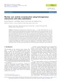
3.2.3 Model III
Thermal calculation model for the heat exchangers, HX1
and HX2, related to the SDCS, for the operation in failure
mode of the SDCS. This model concerns the time evolution
of the temperature in PHTS.
According to the results, the parameter values for the
heat transfer of the heat exchangers HX1 and HX2, at the
moment of achieving the cooling requirement for PHTS
(temperature in PHTS must be 54 °C) are shown in Table 4.
Figure 2 is a plot of temperature decrease of PHTS
coolant for the inlet and outlet of the SDCS heat
exchangers.
Table 2. Hydraulic analysis. Model I.
Component Flow rate (L/s)
Flow through P1 SDCS 115
Flow through P2 SDCS 114
Flow through HX1 SDCS 104
Flow through HX2 SDCS 103
Flow through inlet
collectors HD6, HD2, HD4, HD8
HD6: 104
HD2: 1.4 10
–10
HD4: 2.27 10
–9
HD8: 103
Flow through outlet
collectors HD5, HD1, HD3, HD7
HD5: 104
HD1: 1.85 10
–9
HD3: 1.73 10
–9
HD7: 103
Flow through P1, P2, P3, P4 PHTS P1: 4 10
–10
P2: 1.55 10
–9
P3: 54
P4: 54
Flow through fuel
channels R1, R2, R3 and R4
R1: 2.15 10
–10
R2: 50
R3: 1.79 10
–9
R4: 50
Table 3. Hydraulic analysis. Model II.
Component Flow rate (L/s)
Flow through P1 SDCS 115
Flow through P2 SDCS 1.7
Flow through HX1 SDCS 104
Flow through HX2 SDCS 1.9
Flow through inlet
collectors HD6, HD2, HD4, HD8
HD6: 104
HD2: 7.75 10
–12
HD4: 7.3 10
–12
HD8: 1.9
Flow through outlet
collectors HD5, HD1, HD3, HD7
HD5: 104
HD1: 4.14 10
–12
HD3: 4.11 10
–12
HD7: 1.9
Flow through P1,P2, P3, P4 PHTS P1: 4.97 10
–12
P2: 5.2 10
–12
P3: 67
P4: 34.8
Flow through fuel
channels R1, R2, R3 and R4
R1: 6.9 10
–12
R2: 36.7
R3: 5 10
–12
R4: 36.7
Table 4. Thermal analysis. Model III.
Thermal load of SDCS HX1/HX2 10.99 MW(th)
Outlet temperature for D
2
O of PHTS 54.06 °C
Outlet temperature for the cooling
water of SDCS HX1 and HX2
30.165 °C
Fig. 2. Examination for 2 HX for cooling agent 30 °C.
4 D.L. Icleanu et al.: EPJ Nuclear Sci. Technol. 1, 13 (2015)
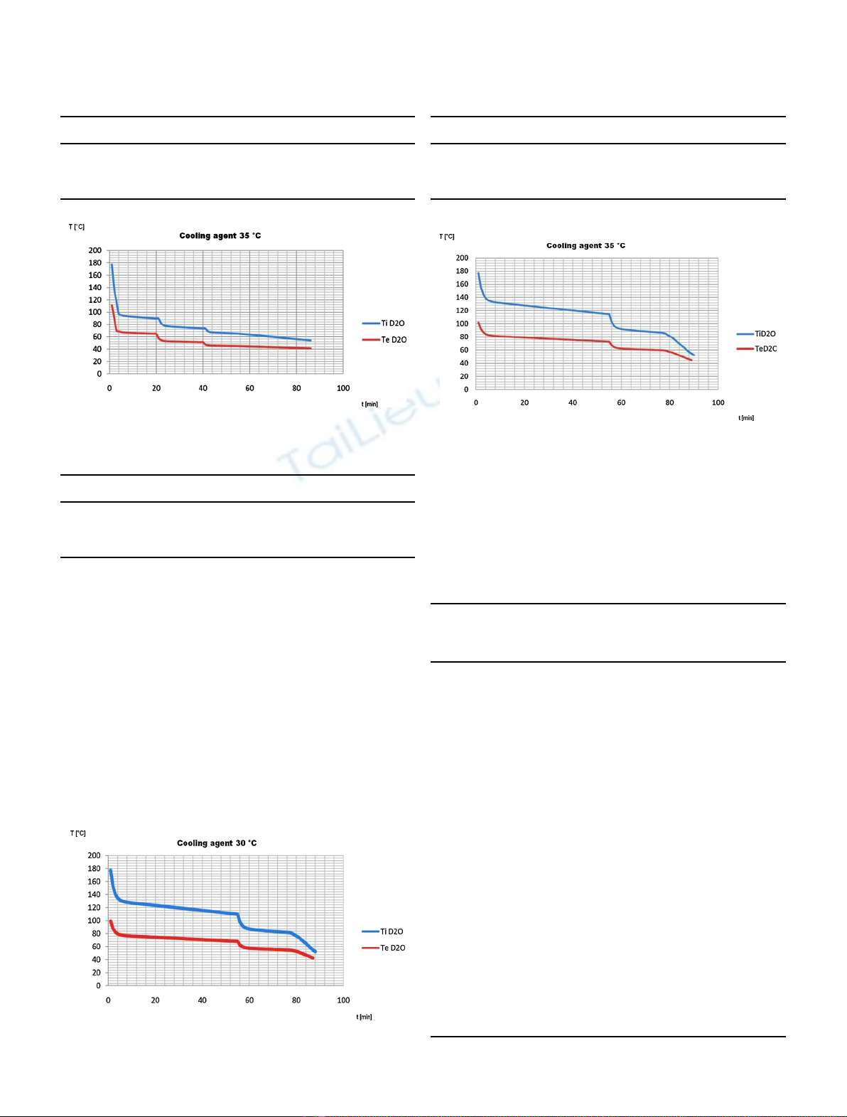
3.2.4 Model IV
Thermal calculation model for the heat exchangers, HX1
and HX2, related to the SDCS, for the operation of the
SDCS under failure mode (LOCA). The inlet temperature
on the secondary side of the heat exchangers is 35 °C. In
model IV, the SDCS is working with its own pumps, P1 and
P2. The results are shown in Table 5.
Figure 3 is also a plot of temperature decrease of PHTS
coolant for the inlet and outlet of the SDCS heat
exchangers. The difference between model III and model
IV is the inlet temperature of the cooling water that passes
through the heat exchangers.
3.2.5 Model V
Thermal calculation model for the heat exchangers, HX1 or
HX2, related to the SDCS, for the operation in failure mode
of the SDCS (LOCA).
Table 5. Thermal analysis. Model IV.
Thermal load of SDCS HX1/HX2 8.95 MW(th)
Outlet temperature for D
2
O of PHTS 54.16 °C
Outlet temperature for the cooling
water of SDCS HX1 and HX2
41.32 °C
Fig. 3. Examination for 2 HX for cooling agent 35 °C.
Table 6. Thermal analysis. Model V.
Thermal load of SDCS HX1/HX2 5.4 MW(th)
Outlet temperature for D
2
O of PHTS 52.43 °C
Outlet temperature for the cooling
water of SDCS HX1 and HX2
41.18 °C
Fig. 4. Examination for 1 HX for cooling agent 30 °C.
Table 7. Thermal analysis. Model VI.
Thermal load of SDCS HX1/HX2 4.17 MW(th)
Outlet temperature for D
2
O of PHTS 52.2 °C
Outlet temperature for the cooling
water of SDCS HX1 and HX2
43.5 °C
Fig. 5. Examination for 1 HX for cooling agent 35 °C.
Table 8. Comparative results from the hydraulic analyses.
Model I.
Data obtained
by using
Pipenet (L/s)
Data obtained
by using
Flowmaster (L/s)
Flow through P1 118.4 115
Flow through P2 118.4 114
Flow through HX1 106.6 104
Flow through HX2 106.6 103
Flow through
inlet collectors
HD6: 106.6 HD6: 104
HD2: 0 HD2: 1.4 10
–10
HD4: 0 HD4: 2.27 10
–9
HD8: 106.6 HD8: 103
Flow through
outlet collectors
HD5: 106.6 HD5: 104
HD1: 0 HD1: 1.85 10
–9
HD3: 0 HD3: 1.73 10
–9
HD7: 106.6 HD7: 103
Flow through
PHTS pumps
P1: 0 P1: 4 10
–10
P2: 0 P2: 1.55 10
–9
P3: 58.6 P3: 54
P4: 58.6 P4: 54
Flow through
fuel channels
R1: 0 R1: 2.15 10
–10
R2: 53 R2: 50
R3: 0 R3: 1.79 10
–9
R4: 53 R4: 50
D.L. Icleanu et al.: EPJ Nuclear Sci. Technol. 1, 13 (2015) 5


![Đề ôn tập cuối kỳ môn Kỹ thuật nhiệt - Nhiệt động học [mới nhất]](https://cdn.tailieu.vn/images/document/thumbnail/2026/20260310/hoaphuong0906/135x160/60681773197823.jpg)

![Bài giảng thang máy và thang cuốn: Tổng hợp kiến thức [chuẩn nhất]](https://cdn.tailieu.vn/images/document/thumbnail/2026/20260310/hoaphuong0906/135x160/41471773283876.jpg)
