
REGULAR ARTICLE
Flexblue
®
core design: optimisation of fuel poisoning for a soluble
boron free core with full or half core refuelling
Jean-Jacques Ingremeau*
,
** and Maxence Cordiez*
DCNS, France, 143 bis, avenue de Verdun, 92442 Issy-les-Moulineaux, France
Received: 6 May 2015 / Received in final form: 10 September 2015 / Accepted: 6 October 2015
Published online: 09 December 2015
Abstract. Flexblue
®
is a 160 MWe, transportable and subsea-based nuclear power unit, operating up to 100 m
depth, several kilometers away from the shore. If being underwater has significant safety advantages, especially
using passive safety systems, it leads to two main challenges for core design. The first one is to control reactivity in
operation without soluble boron because of its prohibitive drawbacks for a submerged reactor (system size,
maintenance, effluents, and safety considerations). The second one is to achieve a long cycle in order to maximise
the availability of the reactor, because Flexblue
®
refuelling and maintenance will be performed in a shared
support facility away from the production site. In this paper, these two topics are dealt with, from a neutronic
point of view. Firstly, an overview of the main challenges of operating without soluble boron is proposed (cold
shutdown, reactivity swing during cycle, load following, xenon stability). Secondly, an economic optimisation of
the Flexblue
®
core size and cycle length is performed, using the QUABOX/CUBBOX code. Thirdly, the fuel
enrichment and poisoning using gadolinium oxide are optimized for full core or half core refuelling, with the
DRAGON code. For the specific case of the full core refuelling, an innovative heterogeneous configuration of
gadolinium is used. This specific configuration is computed using a properly adapted state-of-the-art calculation
scheme within the above-mentioned lattice code. The results in this specific configuration allow a reactivity curve
very close to the core leakage one during the whole cycle.
1 Introduction
Flexblue
®
is a Small Modular Reactor (SMR) delivering
160 MWe to the grid. The power plant is subsea-based (up to
100 m depth and a few kilometers away from the shore) and
transportable (Tab. 1). It is entirely manufactured in shipyard
and requires neither levelling nor civil engineering work,
making the final cost of the output energy competitive.
Thanks to these characteristics and its small electrical output,
Flexblue
®
makes the nuclear energy more accessible for
countries where regular large land-based nuclear plants are
not adapted, and where fossil-fuelled units currently prevail on
low-carbon solutions. Immersion provides the reactor with an
infinite heat sink –the ocean –around the containment
boundary, which is a cylindrical metallic hull hosting the
nuclear steam supply systems.
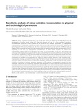
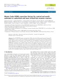
Several modules can be gathered into a single seabed
production farm and operate simultaneously (Fig. 1). The
reactor is meant to operate only when moored on the seabed.
Every 3 years, production stops and the module is emerged
and transported back to a coastal refuelling facility which
hosts the fuel pool. This facility can be shared between several
Flexblue
®
modules and farms. During operation, each module
is monitored and possibly controlled from an onshore control
center. Redundant submarine cables convey both information
and electricity output to the shore. A complete description of
the Flexblue
®
concept, including market analysis, regulation
and public acceptance, security and environmental aspects
can be found in reference [1]. A more detailed description of the
PWR reactor design and the thermal-hydraulic accident
analysis can also be found in reference [2].
The purpose of this paper is to present a suitable design
of the Flexblue
®
core, taking into account the specificities
of the reactor. The first major option of this reactor is a
soluble boron free control, which is analyzed in Section 2.
The second main core characteristic is a three-year-long
cycle. This duration together with the core size, enrich-
ment and the refuelling scheme are justified, using an
economic analysis, in Section 3. In the last part, an
optimization of the burnable poison (gadolinium [Gd]) in
the fuel assembly is performed, using an innovative
heterogeneous configuration.
*Present address: IRSN, 31, avenue Division Leclerc, 92260
Fontenay-aux-Roses, France
**e-mail: jjingremeau@gmail.com
EPJ Nuclear Sci. Technol. 1, 11 (2015)
©J.-J. Ingremeau and M. Cordiez, published by EDP Sciences, 2015
DOI: 10.1051/epjn/e2015-50025-3
Nuclear
Sciences
& Technologies
Available online at:
http://www.epj-n.org
This is an Open Access article distributed under the terms of the Creative Commons Attribution License (http://creativecommons.org/licenses/by/4.0),
which permits unrestricted use, distribution, and reproduction in any medium, provided the original work is properly cited.

2 Operating without soluble boron
2.1 Motivations
The use of soluble boron in the primary coolant is very
common in large electricity generator PWR, such as French
EDF or American ones. It is used there for three main
purposes:
–cold shutdown: in these reactors soluble boron is the only
system able to provide sufficient negative reactivity to
achieve cold shutdown;
–reactivity swing during cycle: the use of soluble boron
enables to mitigate the high reactivity of fresh fuel and to
control the reactivity during the fuel depletion;
–load following: soluble boron is a convenient manner to
control reactivity during short and limited variation of
reactivity (load following, xenon transient).
Moreover, soluble boron has the advantage to be
homogeneously distributed in the core, which is favorable
to flatten the power distribution in order to reduce the
power peak.
But, in the Flexblue
®
case, it has significant drawbacks.
First of all, the use of soluble boron requires voluminous
recycling systems, that cannot be afforded in the limited
space available in an underwater reactor. Furthermore,
these systems require frequent maintenance, which is
hardly suitable for Flexblue
®
. Finally, operating without
soluble boron also eliminates all the boron dilution
accidents. This point is particularly important for severe
accidents, if the flooding of the reactor compartment by sea-
water is considered; in such a case, if soluble boron is
required to achieve cold shutdown, criticality may occur.
This last point, even if associated to a very unlikely
accident, prohibits the use of soluble boron for Flexblue
®
.
A soluble boron free reactor also has significant safety
advantages, such as less primary corrosion, an increased
moderator coefficient (in absolute value) which is favorable
for several accidents (uncontrolled control rod withdraw,
unprotected loss of flow accident...),
1
and no criticality in
case of main steam line break (in such an accident, the core
cooling could be sufficient to make the core critical even
with all the control rods inserted in reactors using soluble
boron).
The manners to solve the cold shutdown and load
following issues in a soluble boron free reactor are presented
below, together with a consideration about the shutdown
system redundancy. The way to solve the reactivity swing
during cycle is analyzed in Section 4.
2.2 Cold shutdown
Due to moderator effect, the reactivity strongly increases
between the hot and cold shutdown (around 5,000 pcm),
and a safety margin of negative reactivity of 5,000 pcm is
also required [3,4]. In order to provide this negative
reactivity without soluble boron, the only manner is to
increase the control rod worth. Several ways can be
investigated:
–use of particularly absorbing materials, such as enriched
boron or Hafnium [5]; control rod using B
4
C with 90% of
10
B worth 40% more than with natural boron
2
in an
infinite medium;
–an increased number of control rod pins: the use of 36 pins
(compared to the classical 24 for 17 17 fuel assembly) can
increase the control rod worth of 70%
2
(250%
2
using
enriched B
10
)inaninfinite medium. But these attractive
results are not directly applicable, because in a real core,
the control rods only cover a fraction of the core, and a
space-shielding effect in controlled fuel assemblies strongly
limits the negative reactivity of those solutions. For
example, a 97 standard 17 17 fuel assembly’s core, with
half of them controlled with 24-pins control rods using
enriched boron, with optimized poisoning (Sect. 4.2), does
not achieve cold shutdown. With the most reactive rod
stuck above the core, the reactivity is positive, around
2000 pcm;
–an increased number of control rods; another way to
avoid this space-shielding effect is to increase the number
of rodded fuel assemblies, above 50% possibly up to 100%
Table 1. Flexblue
®
module main characteristics.
Parameter Value
Unit power rating 160 MWe
Length 150 m
Diameter 14 m
Immersion depth 100 m
Lifetime 60 years
Fig. 1. Artist view of a Flexblue
®
farm.
1
A high moderator coefficient (in absolute value) is however
unfavorable to overcooling accidents, such as main steam line
break. But, this is not a drawback for soluble boron free reactor
compared to reactor using soluble boron; indeed both have the
same maximum moderator coefficient (in absolute value), at end
of cycle when both do not have soluble boron in their primary
coolant. The impact to be soluble boron free only reduces the
moderator coefficient variation from approximately –40 pcm/°C
in begin of cycle to –60 pcm/°C at end of cycle compared to
∼0 pcm/°Cto–60 pcm/°C for soluble boron reactors. As safety
studies only consider the maximum coefficient, it has no impact.
Moreover, concerning the main steam line break accident, as there
is no criticality after automatic shutdown (thanks to the increased
control rod worth) in soluble free reactor, it is much less an issue.
2
These results have been obtained with QUABOX/CUBBOX,
using cross-section libraries generated with DRAGON (Sect. 4).
2 J.-J. Ingremeau and M. Cordiez: EPJ Nuclear Sci. Technol. 1, 11 (2015)

of the core. Calculations performed for this paper show
that for 100% of fuel assemblies rodded, even with 24 pins
of natural B
4
C or AIC, cold shutdown is easily achieved
(–7,000 pcm for the above-mentioned core, with the most
reactive rod stuck).
3
But, this last solution has a major
limitation: the current size of Control Drive rod
Mechanism (CDM), ∼30 cm, is larger than the fuel
assembly size (21.5 cm). That is why in current French
PWR, the fraction of rodded fuel assemblies is always
below 50% and diagonally spread in the core
4
(Fig. 2).
A way to solve this issue is to insert the control rod
mechanism inside the reactor primary vessel; this exempts
them to stand the pressure difference (155 bars –1 bar), and
enables to make them more compact. For example,
Babcock and Wilcox have chosen this solution for the
mPower integral reactor.
5
But it does not really suit the
Flexblue
®
reactor, which is a loop type reactor. Further-
more, the development of such immerged CDM could be
long, risky and costly.
For the Flexblue
®
case, another option has been
preferred: it consists in using more compact external CDM.
Indeed, the CDM size is mainly imposed by the control rod
weight and the primary pressure. If immerged CDM use the
lack of pressure to reduce CDM size, reducing the weight
can also be an option. For a SMR concept such
as Flexblue
®
, the reduced height (2.15 m of fissile height
compared to around 4 m for large land-based PWR)
automatically divides by two the control rod weight. The
power required in the CDM is therefore also divided by two,
and, for a constant height the CDM radial side could be
reduced by approximately p2, and fitted with the fuel
assembly dimensions. This solution, requiring less develop-
ment than immerged CDM, is the reference for Flexblue
®
reactor.
Another way to cover 100% of fuel assemblies with
classical CDM is to use bigger control rods, recovering
several fuel assemblies. That is the idea developed by DCNS
in four patent applications [6–9];
–adapted fuel assemblies: another way to cover 100% of the
core with control rods is to use larger assemblies, in order
to have the same size for fuel assemblies and CDM. For
example, 21 21 fuel assemblies, with a moderator ratio
of 3 (compared to 2 for current standard PWR, meaning
more water between the pins) have a size of around 30 cm.
But the change of a standard 17 17 fuel assembly to a
21 21 larger fuel assembly would have a significant
impact on all the fuel facilities, and may raise criticality
issues. That is why the reduced size CDM is preferred to
this solution.
Several solutions can be combined in order to achieve
cold shutdown. For example, reference [10] uses 28 control
rods pins for a 17 17 lattice, and a fraction of rodded fuel
assemblies of 62%. Reference [5] uses Hf as absorber, an
increased number of control rods pins, an increased
moderator ratio (2.5) and a fraction of rodded fuel
assemblies below 50%.
In conclusion, several ways are possible to achieve cold
shutdown without soluble boron. Without significant
modifications in the fuel assembly, a fraction of rodded
fuel assemblies above 50% is required. The reference
solution for the Flexblue
®
project is to keep a standard
(but shortened) 17 17 fuel assembly, and to adapt the
design of the CDM in order to be able to insert a control rod
in every assembly in the core. This solution has been chosen
for its minimal required developments.
2.3 Xenon stability and load following
In large current PWR, boron is used in order to limit the
control rod displacement and avoid the risk of axial xenon
instabilities (increase of axial power oscillations due to
xenon). For Flexblue
®
, the limited fissile height (2.15 m) is
very favourable in terms of stability. In order to analyse the
risk of xenon axial instability, a simplified conservative
analytical model based on reference [11] has been used. The
model estimates the maximum fissile height for which xenon
oscillations are stable, for an axially uniform power profile
(conservative hypothesis for stability), as a function of linear
power (assuming a standard 17 17 fuel assembly) and
enrichment.
6
The results, presented inFigure3, show that for
a 5% enrichment, and a linear power below 125 W/cm
(Flexblue
®
core), the stability limit is estimated above
3
It is not necessary to have 100% of rodded fuel assemblies; a
fraction around 70–80% seems to be enough (function of the
enrichment, size of the core and fuel refuelling strategy). But, this
point should be more deeply studied.
4
The CDM lattice is diagonally oriented compare to the fuel
assembly lattice.
5
www.generationmpower.com.
Fig. 2. Control rod position in the EPR Core.
6
The xenon density, and neutronic worth are directly dependent
on the fission rate (by producing
135
I), i.e. the linear power. The
xenon density is also function of the neutron flux (for captures),
which is strongly dependent on the enrichment for a given power
density.
Fig. 3. Limit fissile height for axial xenon stability.
J.-J. Ingremeau and M. Cordiez: EPJ Nuclear Sci. Technol. 1, 11 (2015) 3

2.8 m. Accordingly, despite the uncertainty of the model, it
can be assumed that xenon oscillations are stable in the
Flexblue
®
core. Oscillations may occur consequently to a
load follow, or a significant control rod movement, but they
will decrease, without leading to safety concerns. Reference
[10] even claims to be able to design a soluble boron free core,
stable with 3.8 m of fissile height using axially heterogeneous
poisoning.
Soluble boron is also currently used to manage
significant reactivity variations due to xenon poisoning
during a load follow. The way to manage it in a soluble
boron free core has been well studied in references [12,13].
The idea is to adapt the average coolant temperature during
a transient, in order to use moderator effect to balance the
xenon variations. Control rod movements are also required
during such a transient, in order to limit the temperature
variations, but the study in reference [12] concludes that they
are small enough to keep an acceptable form factor.
2.4 Other safety considerations
The soluble boron suppression also raises some other safety
considerations. Firstly, a safety requirement of the European
Utility requirements [3], similar to a requirement of the NRC
in reference [14], is: ‘The control of the core reactivity shall be
accomplished by means of at least two independent and
diverse systems for the shutdown’. Usually, boron and
control rods are these diverse shutdown systems. That is
why, even if the reactor is soluble boron free in normal
operation, the Flexblue
®
auxiliary systems include an
emergency boron injection system, similar to VVER ones
[15]. It consists of two tanks, full of borated water at the
primary pressure, connected to the primary pumps (Fig. 4).
In case of an Anticipated Transient Without Scram
(ATWS), the pump inertia provides the passive injection in
the cold leg. After such an injection, the reactor must be
transported back to a coastal maintenance facility in order
to remove the boron.
Secondly, the reduced weight of control rods has also an
impact on their falling time, which is expected to be slightly
increased. The impact of this increase cannot be evaluated
at this project phase but has to be carefully considered for
future detailed transient studies.
2.5 Control rod ejection
For SMR reactors, the control rod ejection is much more
problematic compared to large PWR. Indeed, due to the
small core size, the neutronic worth of each control rod
is strongly increased, reaching 5,000 pcm for a 24 pins,
natural B
4
C control rod, in a 77 assemblies core. This value
has to be compared to approximately 600 pcm for the same
control rod in a large PWR, which is high enough to lead to
prompt-criticality, a power excursion up to 10 times the
nominal power and an energy release of 75% of the safety
related criterion of 200 cal/g [16]. Considering that the
energy release is roughly proportional to r
CR
-b(where r
CR
is the control rod worth and bthe delayed neutron
fraction)
7
, it is clear that the safety criterion cannot be
respected with such insertion of reactivity (up to 30 times
the criterion). Even with a control rod of 2000 pcm, the
criterion is 10 times exceeded.
Furthermore, for Flexblue
®
, this point is emphasized
by the soluble boron free conception; the control rods are
inserted deeper and for a longer time in the core, for long-
term reactivity variation and Axial Offset regulation. This
makes the control rod ejection accident more likely and
even more problematic. Additionally, a control rod ejection
may deteriorate the third containment barrier (the module
hull), if a dedicated protection is not added above the
reactor. However, this place is very critical in terms of
component arrangement, due to the module compactness.
All these reasons make the control rod ejection a potential
issue for safety. That is why, within the Flexblue
®
project,
the strategy is to eliminate the possibility of a control rod
ejection. This is achievable using anti-ejection devices, such
as described in CEA or Combustion Engineering patents in
references [17–19]. Many patents on preventing control rod
ejection devices can be found, some associated with “nut
screw”CDM, others with “pawl-push”ones. There are too
many to be all listed and described here.
This problem is another reason why a re-design of a
specific CDM is required for Flexblue
®
, taking into account
two major issues: to be sufficiently compact to achieve one
CDM by fuel assembly (to reach cold shutdown), and to
eliminate the control rod ejection accident.
2.6 Conclusion
In conclusion, one of the main challenges to operate without
soluble boron is achieving cold shutdown. In addition, one
of the main challenges of designing a SMR core, especially a
soluble boron free one, is control rod ejection accident.
These two issues can be solved, keeping a standard 17 17
fuel assembly, by using an adapted CDM, more compact, in
order to be able to insert one control rod per assembly, and
integrating an anti-control-rod-ejection device. The fol-
lowing assumes that such CDM is achieved. The reduced
fissile height of the core ensures the stability of axial xenon
oscillation, and the load follow can be managed by adapting
the coolant average temperature. In order to fitsafety
requirements, a passive emergency boron injection is
added.
The last main challenge for operating a Flexblue
®
without soluble boron is to manage the reactivity swing
Fig. 4. Scheme of the Emergency Boron Injection.
7
www.cea.fr/energie/la-neutronique/ (in French).
4 J.-J. Ingremeau and M. Cordiez: EPJ Nuclear Sci. Technol. 1, 11 (2015)

during cycle. This last point will be presented in Section 4.
Meanwhile the next part describes the core design strategy
and results.
3 Core design
3.1 QUABOX/CUBBOX calculations and control
rods regulation
QUABOX/CUBBOX is a diffusion 3D code, developed by
GRS (in German “Gesellshaft für Anlagen- und Reacktor-
sicherheit”). It is integrated in all the GRS reactor physics
chain, and especially coupled to ATHLET code for
neutronic/thermal-hydraulic transients. It has been vali-
dated by benchmark (see for example Refs. [20,21]).
In this study, QUABOX/CUBBOX uses library cross-
sections generated by DRAGON (Sect. 4.3). The coupling
between the two codes has been developed by DCNS in
Python. A validation of this new calculation chain has been
performed on standard and Cyclades refuelling strategies
on 900 MWe French PWR, with a few percents of
discrepancy on burn-up and cycle length.
Cycle calculations have been performed with imposed
temperature profile and moderator density (no thermal-
hydraulic feedback). For the soluble boron free operation,
the current version of the code uses a very simplified control
rod regulation; all groups are inserted or withdrawn at the
same time, keeping a constant relative distance. These
simplifications have a quite small impact on the cycle
length, but strongly limit the ability of the current version
to estimate precise form factors. Despite these limitations,
some optimizations of the refuelling scheme have been
performed, and some 3D form factors are presented below,
in order to evaluate the performance of poisoning
optimization. These values are not very accurate, but give
a good idea of what kind of performance can be achieved.
In order to control the Axial Offset, a fuel with
heterogeneity has been used, considering a layer of 21.5 cm
for two-batch cycle and 18 cm for single-batch without Gd
at the top of the core.
3.2 Methodology
Considering that the transportation, between the production
site and the refuelling facility, might have an impact on the
average availability, the focus has been placed on the following
features. Firstly, the conception of the module and the
maintenance planning are optimized to shorten the mainte-
nance duration, especially using standard exchange for some
components. Secondly, and that is this paper’sobjective,the
core has been designed to optimize the cycle length in order to
minimize the Levelized Cost of Energy (LCOE).
The optimized cycle is a compromise between the
availability (which is improved by increasing the cycle
length), the fuel cost (which is dependent on the enrichment
and the refuelling strategy: single or two-batch) and the
core size (to increase the reactor vessel size increases the
reactor investment).
One major parameter is the refuelling strategy. Indeed,
a single-batch refuelling (100% of fresh fuel at each
refuelling) enables to reach a long duration cycle, but
misuses the fuel with typical burn-up below 30 GWd/t
UO2
for 5% enrichment. On the other hand, a two-batch
refuelling reduces the cycle length by approximately one
third, compared to a complete refuelling, but increases the
final fuel burn-up by one third,
8
reducing the fuel total cost.
Another key parameter is the core size. Indeed, a bigger
core reduces the power density, and linear power. As a
result, it increases the cycle length (thus the availability)
for a given burn-up. But it also increases the reactor-vessel
cost, and the initial investment to build a module. Taking
into account the financial aspect of this investment, with an
8% actualization rate, it has an impact on the LCOE. The
linear power is also limited by safety considerations,
especially for a soluble boron free core, in which the form
factor is expected to increase (Sect. 3.3).
Considering a major shutdown for maintenance of several
months every 10 years adds another aspect to take into
consideration, because the fuel cycle length should be close
to a fraction of this 10-year cycle. It is worthless to achieve a
32-month cycle, because it is not long enough to have only
two intermediate refuelling shutdowns, and 27 months are
sufficient to have three intermediate shutdowns (Fig. 5). A
margin is useful to provide flexibility for the shutdown
operation date (function of electricity consumption) but is
already provided by stretching possibilities and burn-up
economy realized during load following.
All these parameters have been included in a general
economic model in order to evaluate the LCOE of several
Flexblue
®
farms. This model takes into account some
operation hypotheses (maintenance and transportation
durations), cost evaluation (module, fuel, transportation,
decommissioning, maintenance facility cost including its
own investment and cost strategy), and models for a
progressive development and investment in each farm, all
the financial fluxes, planned shutdowns and electricity
production. In order to evaluate the maximum cycle length
for a given core size, enrichment and refuelling strategy
(single, two or three batches), polynomial interpolations
sets on several hundreds of QUABOX/CUBBOX calcu-
lations are used. These calculations are performed assuming
a standard 17 17 fuel assembly, with a fissile height of
2.15 m. The average quadratic discrepancy between the
interpolations and the calculation is 2%. The model also
optimizes the core enrichment in order to adapt the cycle
length to the number of refuelling shutdowns required, and
8
Using the well-known approximation Bu nðÞ¼2n
nþ1Bu 1ðÞ,
where nis the refuelling strategy (1 for single batch, 2 for two
batch), and Bu the burn-up [22].
Fig. 5. Examples of 10 years Flexblue
®
cycles.
J.-J. Ingremeau and M. Cordiez: EPJ Nuclear Sci. Technol. 1, 11 (2015) 5


![Đề ôn tập cuối kỳ môn Kỹ thuật nhiệt - Nhiệt động học [mới nhất]](https://cdn.tailieu.vn/images/document/thumbnail/2026/20260310/hoaphuong0906/135x160/60681773197823.jpg)

![Bài giảng thang máy và thang cuốn: Tổng hợp kiến thức [chuẩn nhất]](https://cdn.tailieu.vn/images/document/thumbnail/2026/20260310/hoaphuong0906/135x160/41471773283876.jpg)
