
UFC 3-410-04N
25 October 2004
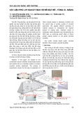
Figure 3-1. Delagging facility floor plan.
3-4 DESIGN CRITERIA. Design the facility using general technical
requirements in Chapter 2 of this UFC and the specific requirements in this Chapter.
3-5 EXHAUST AIR. Design the exhaust air system to generate a minimum
capture velocity of 0.762 m/s (150 fpm) to capture all the contaminants at the source.
3-5.1 Hood Design. Design asbestos delagging hood to enclose the work
piece as much as possible. Do not use small portable hoods with flexible ductwork
because they do not provide consistent capture.
3-5.1.1 Typical Hood Design for High Profile Work Pieces. Figure 3-2 shows a
hood design consisting of a workbench with a central, circular area. Mount the circular
area on sealed bearings to allow easy turning of heavy work pieces. This design is best
for high profile work pieces (for example, boilers, pumps). The hood captures
contaminants through the slots into an exhaust plenum. Design each hood with:
a. Two cleanout doors on the front and two doors on the sides of the hood
for easy access to asbestos debris. Provide two small cutouts in the outer
3-2
Simpo PDF Merge and Split Unregistered Version - http://www.simpopdf.com

UFC 3-410-04N
25 October 2004
corners of the workbench to place large pieces of lagging in double
bagged containment.
b. The top baffle swings up to allow access to overhead cranes.
Figure 3-2. Exhaust hood for high profile work pieces.
3-5.1.2 Typical Hood Design for Low Profile Work pieces. Figure 3-3 shows a
hood design consisting of a workbench with a grating strong enough to support the
heaviest expected work piece. This is a downdraft hood that draws small pieces of
lagging through the grating. The perforated plate below the grating creates even airflow
over the grating. This design is best for low profile work pieces such as piping. Design
each hood with stands and swinging baffles on each end to accommodate long work
pieces (e.g., pipes).
3-5.3 Ductwork. Size the exhaust ductwork to provide a minimum transport
velocity of 25.4 m/s (5,000 fpm). The high velocity is necessary because the practice of
wetting the fibers makes them heavier and more difficult to transport. See paragraph 2-
4.1 for general duct considerations.
3-3
Simpo PDF Merge and Split Unregistered Version - http://www.simpopdf.com

UFC 3-410-04N
25 October 2004
Figure 3-3. Exhaust hood for low profile work pieces.
3-5.4 Fans. See paragraph 2-4.2 for general fan considerations.
3-5.5 Weather Stack Design and Location. See paragraph 2-4.3.
3-5.6 Air Cleaning Devices. A delagging facility requires multistage filtering,
which consists of a fabric filter collector, prefilters, a mist eliminator, and high efficiency
particulate air (HEPA) filters. Prefilters extend the life of the HEPA filters. Use "bag in,
bag out" styles of HEPA filters, which allow for safe replacement of the filter element
without exposure to asbestos. A mist eliminator before the HEPA filter protects it from
the moisture generated during asbestos removal.
a. Have all collectors deliver the collected asbestos to a common pickup
point to minimize the risk of exposure. Provide a double acting valve at
each collector hopper throat, in accordance with the ACGIH IV Manual,
Chapter 4.
b. Use a single chamber, shaker type collector to minimize the number
of collection points.
3-5.6.1 Filter Efficiency. The fabric filter collector requires a minimum efficiency
reporting value (MERV) of not less than 15 in accordance with ASHRAE 52.2, Method
3-4
Simpo PDF Merge and Split Unregistered Version - http://www.simpopdf.com

UFC 3-410-04N
25 October 2004
of Testing General Ventilation Air Cleaning Devices for Removal Efficiency by Particle
Size.
3-5.6.2 Sequencing. Figure 3-4 illustrates the required sequence of air cleaning
devices.
Figure 3-4. Sequence of air cleaning devices for asbestos delagging.
3-5.7 Industrial Vacuum System. Provide a low volume, high velocity (LVHV)
central vacuum system at delagging shops to exhaust fibers and dust from power tools
(e.g., grinders and saws) when they are used, as specified in 29 CFR 1910.1001.
3-5.7.1 Design a central vacuum cleaning system, which consists of a motor
driven exhauster interconnected with bag type separators.
3-5.7.2 Connect the separator to rigid tubing, which extends throughout the plant.
Terminate the rigid tubing with inlet valves at the various workstations. Provide flexible
hose connections to allow workers to do shop cleanup and to decontaminate their
protective outerwear.
3-5.7.3 Use local exhaust hoods and high velocity exhaust takeoffs for each hand
tool. Table 3-1 and the ACGIH IV Manual provide examples of tools and exhaust
system for specific operations.
3-5.7.4 Ensure proper capture velocity is produced at each local exhaust hood.
Design vacuum systems to reach within 12.7 mm (1/2 inch) of the contaminant source.
3-5.7.5 Design the pickup air-stream to have a velocity of two to three times the
generation velocity for particle sizes from 20 to 30 micrometers (20 to 30 micron.)
Design for an additional velocity of: (1) four to five times the generation velocity to pull
the particles up through 300 U.S. standard mesh, or (2) six to eight times the generation
velocity to pull the particles up through a 20 U.S. standard mesh.
3-5
Simpo PDF Merge and Split Unregistered Version - http://www.simpopdf.com

UFC 3-410-04N
25 October 2004
TABLE 3-1. Minimum Volumes and Vacuum Hose Size for Asbestos Operations
Hand Tool
Flow rate
m3/s (cfm)
Hose Size
mm (in.)
Pneumatic chisel
Radial wheel grinder
Cone wheel grinder, 2 inch
Cup stone grinder, 4 inch
Cup type brush, 6 inch
Radial wire brush, 6 inch
Hand wire brush, 3 x 7 inches
Rip out knife
Rip out cast cutter
Saber saw
Saw abrasive, 3 inch
General vacuum
0.06 (125)
0.07 (150)
0.07 (150)
0.09 (200)
0.12 (250)
0.08 (175)
0.06 (125)
0.08 (175)
0.07 (150)
0.07 (150)
0.07 (150)
0.09 (200)
38 (1.5)
38 (1.5)
38 (1.5)
51 (2.0)
51 (2.0)
38 (1.5)
38 (1.5)
38 (1.5)
38 (1.5)
38 (1.5)
38 (1.5)
51 (2.0)
Adapted from: Hoffman Air and Filtration Systems, “Design of Industrial Vacuum Cleaning Systems and
High Velocity, Low Volume Dust Control.”
3-5.7.6 Design the air volume for no less than two parts of air to one part of
asbestos to be captured by weight.
3-5.7.7 Design the vacuum hose length less than 7.6 m (25 ft). Locate inlet
valves 9 to 10.7 meters (30 to 35 feet) apart when a 7.6-m (25-ft) length of hose is used.
Locate tool vacuum hose connection on the ends of the workbench underneath the
stands. Size the hose based on: (1) air volume per hose, (2) number of hoses to be
used simultaneously, and (3) air velocity required to convey the material to the
separators.
3-5.7.8 Use single-ply, lightweight thermoplastic or polyvinyl chloride (PVC)
flexible hose, but limit the usage whenever possible.
3-5.7.9 Use a multistage centrifugal blower for the vacuum system. Size the
blower for: (1) total system pressure loss associated with the total number of hoses to
be used simultaneously, and (2) maximum exhaust flow rate entering the inlet of the
blower.
3-5.7.10 Feed the blower directly into the bag house used by the industrial exhaust
system (see Figure 3-5) to minimize the number of asbestos collection points.
3-6
Simpo PDF Merge and Split Unregistered Version - http://www.simpopdf.com

![Đá nội thất: Vai trò, phân loại và ứng dụng [A-Z]](https://cdn.tailieu.vn/images/document/thumbnail/2020/20200422/damynghehuyhung/135x160/4231587532359.jpg)


![Sổ tay Thông gió Công nghiệp (Industrial Ventilation HandBook_b_8) [Hướng dẫn chi tiết]](https://cdn.tailieu.vn/images/document/thumbnail/2012/20120202/luly_meo1/135x160/industrial_ventilation_b_split_9_5237.jpg)
![Sách Hướng Dẫn Thông Gió Công Nghiệp (Industrial Ventilation HandBook_b_7) [PDF]](https://cdn.tailieu.vn/images/document/thumbnail/2012/20120202/luly_meo1/135x160/industrial_ventilation_b_split_8_3097.jpg)


![Cẩm nang Gia công kim loại Việt Nam [mới nhất]](https://cdn.tailieu.vn/images/document/thumbnail/2026/20260513/baobinh_011/135x160/7971778670576.jpg)


![Giáo trình Hàn ống nâng cao (Nghề Hàn - CĐ) Trường Cao đẳng nghề Hải Dương [Mới nhất]](https://cdn.tailieu.vn/images/document/thumbnail/2025/20251212/laphong0906/135x160/47521779076565.jpg)


%20--%3e%3cdefs%3e%3cstyle%3e%20.st0%20{%20fill:%20%23fff;%20}%20.st1%20{%20fill:%20%237800fa;%20}%20%3c/style%3e%3c/defs%3e%3cpath%20class='st1'%20d='M117.78,12.18H43.11c2.9,3.47,4.65,7.94,4.65,12.82,0,5.6-2.3,10.66-6.01,14.29h76.02l7.22-13.56-7.22-13.56Z'/%3e%3cg%3e%3cpath%20class='st0'%20d='M53.58,26.17h-.59v-1.46h.59v-4.96h2.83c1.78,0,2.67.94,2.67,2.82v5.76c0,1.87-.89,2.81-2.67,2.81h-2.83v-4.96ZM55.36,21.37v3.34h1.1v1.46h-1.1v3.34h1.01c.61,0,.91-.37.91-1.1v-5.93c0-.74-.3-1.1-.91-1.1h-1.01Z'/%3e%3cpath%20class='st0'%20d='M65.99,31.14h-1.8l-.31-2.07h-2.19l-.31,2.07h-1.64l1.82-11.39h2.62l1.82,11.39ZM65.28,18.04c-.25.46-.51.77-.75.94-.21.15-.47.22-.79.22-.26,0-.57-.07-.92-.22l-.38-.15c-.14-.05-.26-.07-.37-.07-.3,0-.53.18-.71.54l-.91-.68c.25-.46.51-.77.75-.94.21-.14.48-.21.79-.21.26,0,.57.07.92.21l.38.15c.14.05.26.07.37.07.3,0,.53-.18.71-.54l.91.68ZM61.91,27.52h1.73l-.87-5.76-.87,5.76Z'/%3e%3cpath%20class='st0'%20d='M74.53,26.89v1.52c0,1.91-.89,2.86-2.67,2.86s-2.67-.95-2.67-2.86v-5.93c0-1.91.89-2.86,2.67-2.86s2.67.95,2.67,2.86v1.11h-1.69v-1.22c0-.75-.31-1.12-.93-1.12s-.93.37-.93,1.12v6.15c0,.74.31,1.11.93,1.11s.93-.37.93-1.11v-1.63h1.69Z'/%3e%3cpath%20class='st0'%20d='M81.4,31.14h-1.8l-.31-2.07h-2.19l-.31,2.07h-1.64l1.82-11.39h2.62l1.82,11.39ZM75.9,19.2l1.52-1.91h1.71l1.51,1.91h-1.61l-.76-.95-.75.95h-1.61ZM77.32,27.52h1.73l-.87-5.76-.87,5.76ZM83.1,15.99l-1.76,1.91h-1.26l1.17-1.91h1.86Z'/%3e%3cpath%20class='st0'%20d='M84.86,19.75c1.78,0,2.67.94,2.67,2.82v1.48c0,1.87-.89,2.81-2.67,2.81h-.85v4.28h-1.79v-11.39h2.64ZM84.01,21.37v3.86h.85c.58,0,.87-.36.87-1.08v-1.71c0-.71-.29-1.07-.87-1.07h-.85Z'/%3e%3cpath%20class='st0'%20d='M93.51,19.75c1.78,0,2.67.94,2.67,2.82v1.48c0,1.87-.89,2.81-2.67,2.81h-.85v4.28h-1.79v-11.39h2.64ZM92.66,21.37v3.86h.85c.58,0,.87-.36.87-1.08v-1.71c0-.71-.29-1.07-.87-1.07h-.85Z'/%3e%3cpath%20class='st0'%20d='M98.8,31.14h-1.79v-11.39h1.79v4.88h2.03v-4.88h1.83v11.39h-1.83v-4.88h-2.03v4.88Z'/%3e%3cpath%20class='st0'%20d='M105.36,24.55h2.46v1.62h-2.46v3.34h3.09v1.63h-4.88v-11.39h4.88v1.63h-3.09v3.18ZM108.17,17.29l-1.76,1.91h-1.26l1.17-1.91h1.86Z'/%3e%3cpath%20class='st0'%20d='M112.2,19.75c1.78,0,2.67.94,2.67,2.82v1.48c0,1.87-.89,2.81-2.67,2.81h-.85v4.28h-1.79v-11.39h2.64ZM111.35,21.37v3.86h.85c.58,0,.87-.36.87-1.08v-1.71c0-.71-.29-1.07-.87-1.07h-.85Z'/%3e%3c/g%3e%3ccircle%20class='st1'%20cx='25'%20cy='25'%20r='20'/%3e%3cpath%20class='st0'%20d='M32.78,19.27c2.92,0,4.43,2.55,5.28,5.33l.71,2.17c.14.38-.33.75-.71.75h-5.61c.19-.33.24-.71.09-1.08l-.75-2.45c-.43-1.32-.99-2.64-1.79-3.77.75-.57,1.65-.94,2.78-.94h0ZM25,18.38c3.25,0,4.9,2.78,5.89,5.89l.76,2.45c.14.42-.33.8-.8.8h-11.69c-.42,0-.94-.38-.8-.8l.75-2.45c.99-3.11,2.64-5.89,5.89-5.89h0ZM25,11.35c1.74,0,3.11,1.37,3.11,3.11s-1.37,3.11-3.11,3.11-3.11-1.41-3.11-3.11,1.41-3.11,3.11-3.11h0ZM17.27,19.27c1.08,0,1.98.38,2.73.94-.8,1.13-1.37,2.45-1.74,3.77l-.8,2.45c-.14.38-.05.75.09,1.08h-5.56c-.42,0-.9-.38-.75-.75l.71-2.17c.9-2.78,2.41-5.33,5.33-5.33h0ZM17.27,12.91c1.51,0,2.78,1.27,2.78,2.83s-1.27,2.83-2.78,2.83-2.83-1.27-2.83-2.83,1.27-2.83,2.83-2.83h0ZM32.78,12.91c1.56,0,2.78,1.27,2.78,2.83s-1.23,2.83-2.78,2.83-2.83-1.27-2.83-2.83,1.27-2.83,2.83-2.83h0ZM27.07,28.56v.09c0,.57-.24,1.08-.61,1.46h0v.05c-.38.33-.9.57-1.46.57s-1.08-.24-1.46-.61h0c-.38-.38-.61-.9-.61-1.46v-.09h1.41v.09c0,.19.05.38.19.47v.05c.09.09.28.19.47.19s.38-.09.47-.19v-.05c.14-.09.24-.28.24-.47t-.05-.09h1.41ZM30.99,28.56v.09c0,1.65-.66,3.16-1.74,4.24-1.08,1.08-2.59,1.79-4.24,1.79s-3.16-.71-4.24-1.79l-.05-.05c-1.04-1.08-1.7-2.55-1.7-4.2v-.09h1.41v.09c0,1.27.47,2.4,1.27,3.25h.05c.85.85,1.98,1.37,3.25,1.37s2.4-.52,3.25-1.37c.85-.8,1.37-1.98,1.37-3.25v-.09h1.37ZM34.99,28.56v.09c0,2.78-1.13,5.28-2.92,7.07-1.79,1.79-4.29,2.92-7.07,2.92s-5.23-1.13-7.07-2.92c-1.79-1.79-2.92-4.29-2.92-7.07v-.09h1.41v.09c0,2.4.94,4.53,2.5,6.08,1.56,1.56,3.72,2.5,6.08,2.5s4.52-.94,6.08-2.5c1.56-1.56,2.5-3.68,2.5-6.08v-.09h1.41Z'/%3e%3c/svg%3e)