
CÔNG NGHỆ https://jst-haui.vn
Tạp chí Khoa học và Công nghệ Trường Đại học Công nghiệp Hà Nội Tập 60 - Số 11 (11/2024)
82
KHOA H
ỌC
P
-
ISSN 1859
-
3585
E
-
ISSN 2615
-
961
9
INFLUENCE OF MACHINING ERROR OF WORKPIECE
POSITIONING SURFACES ON TOOTH PITCH ERRORS
OF GLEASON SPIRAL BEVEL GEARS
NGHIÊN CỨU ẢNH HƯỞNG CỦA SAI SỐ CHẾ TẠO CÁC BỀ MẶT ĐỊNH VỊ
CỦA PHÔI ĐẾN SAI SỐ BƯỚC RĂNG CỦA BÁNH RĂNG CÔN XOẮN HỆ GLEASON
Dinh Hoang Thuy1, Pham Van Tuan1,
Pham Quoc Hoang1,*
DOI: http://doi.org/10.57001/huih5804.2024.371
ABSTRACT
During the machining process of Gleason spiral bevel gears, errors of workpiece positioning surfaces cause positioning errors
, which is one of the main
reasons for tooth pitch errors. In this paper, the 3D models of Gleason spiral bevel gears was created a
ccording to the machining principle in Autodesk Inventor
software and they were used to simulate the influence of positioning errors on the indicators for evaluating tooth pitch erro
rs, including the maximum single
pitch deviation, the maximum difference b
etween adjacent pitches, and the total cumulative pitch deviation. The research results show that all these indicators
depend linearly on the tilt angle and the distance between the workpiece axis and the z-axis of the machine-tool. Mathematical equations
for determining the
value of these indicators based on the tilt angle and distance between axes are also developed, and the manufacturing accurac
y level of the workpiece positioning
surfaces was determined so that the values of these indicators would not e
xceed 1/3 of the tolerance of DIN 6 accuracy level (according to Standard DIN 3965).
The research results are significant for ensuring accuracy when machining Gleason spiral bevel gears.
Keywords: Spiral bevel gears, Tooth pitch errors, Manufacturing accuracy level.
TÓM TẮT
Trong quá trình gia công bánh răng côn xoắn hệ Gleason, sai số chế tạo các bề mặt định vị của phôi gây ra sai số gá đặt, đây là một trong các nguy
ên nhân
chính tạo ra sai số bước răng. Trong bài báo này, một mô hình 3D của cặp bánh răng côn xoắn hệ Gleason được xây dựng theo nguyên lý gia công b
ằng phần
mềm Autodesk Inventor và được sử dụng để mô phỏng ảnh hưởng của sai số gá đặt đến các chỉ tiêu đánh giá sai số bước răng bao gồm: sai số bước răng đơn l
ớn
nhất, sai lệch hai bước răng liền kề lớn nhất và sai số bước răng tổng lớn nhất. Kết quả nghiên cứu cho thấy, tất cả các chỉ tiêu trên đều phụ thuộc tuyến
tính vào
góc nghiêng và khoảng cách giữa trục phôi và trục z của máy gia công. Từ đó đã tìm ra được các phương trình toán học để tính toán giá trị của các chỉ ti
êu trên
theo góc nghiêng và khoảng cách giữa trục phôi và trục z của máy gia công và đặt ra yêu cầu về cấp chính xác chế tạo của các b
ề mặt định vị của phôi sao cho giá
trị của các chỉ tiêu trên không vượt quá 1/3 dung sai tương ứng với cấp chính xác DIN 6 theo tiêu chuẩn DIN 3965. Kết quả nghiên c
ứu có ý nghĩa quan trọng trong
việc đảm bảo độ chính xác khi gia công bánh răng côn xoắn hệ Gleason.
Từ khóa: Bánh răng côn xoắn, sai số bước răng, cấp chính xác chế tạo.
1Advanced Technology Center, Le Quy Don Technical University, Vietnam
*Email: phqhoang@lqdtu.edu.vn
Received: 10/9/2024
Revised: 28/10/2024
Accepted: 28/11/2024
P-ISSN 1859-3585 E-ISSN 2615-9619 https://jst-haui.vn SCIENCE - TECHNOLOGY
Vol. 60 - No. 11 (Nov 2024) HaUI Journal of Science and Technology 83
1. INTRODUCTION
When transmitting motion and moment between two
non-parallel shafts, the spiral bevel gear transmission is
generally preferred because of its advantages, including
large power transmission capacity, stable ratio,
significant applicable coefficient, and smooth
transmission [1-3]. In industry, there are two main cutting
methods of machining spiral bevel gears: face milling and
face hobbing [4-7].
In terms of shape, face-milled bevel gears have circular
and lengthwise tooth curves (also called Gleason spiral
bevel gears), while face-hobbed gears have extended
epicycloid lengthwise tooth curves. This difference is due
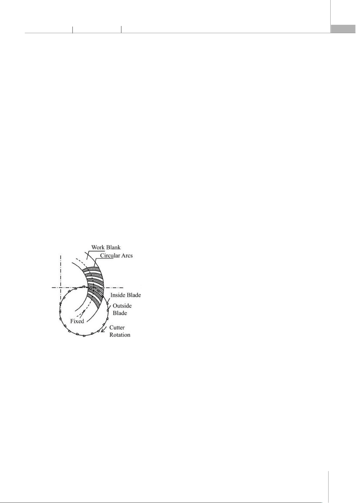
to the cutting kinematics of the two methods. In the face
milling method, only one slot is machined at a time until
the total depth is cut completely. Subsequently, the
workpiece is rotated to the position for machining the
next slot, and the process will be repeated until all tooth
spaces are finished (Figure 1). In the face hobbing
method, all the tooth spaces are cut simultaneously.
Therefore, the face milling method is called the single
indexing method, and the face hobbing method is called
the continuous indexing method.
Figure 1. Kinematic of face milling method [8].
Nowadays, scientists are very interested in reducing
the noise and vibration of spiral bevel gear transmission.
One of the essential reasons for noise and vibration of
spiral bevel gear transmission is tooth pitch errors. To
reduce tooth pitch error, it is first necessary to find out the
reasons of such errors. Machining errors are decomposed
into constant systematic, variable systematic, and
random errors. The reasons for constant systematic errors
can be listed as follows: errors of manufacturing machine,
geometrical errors of cutting tools, errors of cutting
method, and elastic deformation of the process system
(machine, tools, fixtures, workpiece). The variable system
errors appear in large-series production due to wear of
the cutting tool and thermal deformation during the
cutting process. Random errors are caused by several
reasons, such as uneven workpiece hardness, uneven
machining allowance, cutting tool removal, installation,
positioning error.
In this paper, errors due to machines, cutting tools,
and cutting methods are not studied, because they
cannot be changed. The variable systematic errors are
also not analyzed because this paper does not study
large-series production. This paper also does not analyze
errors due to uneven workpiece hardness and uneven
machining allowance because of their difficulty in
control. Thus, there are two reasons of machining errors
that need attention to reduce: elastic deformation of the
process system and positioning errors. The elastic
deformation of the process system depends on the
system stiffness and the cutting force. The positioning
errors are affected by the geometrical error of the fixture
and the manufacturing error of the workpiece
positioning surfaces. If the fixture is manufactured with
high accuracy, its geometrical errors will be so small that
they can be ignored. In that case, the positioning errors
mainly depend on the manufacturing error of the
workpiece positioning surfaces. This paper studies the
influence of the machining error of workpiece
positioning surfaces on tooth pitch errors of face-milled
spiral bevel gears by measuring and calculating the tooth
pitch errors on a 3D-CAD model, that was created with
positioning error simulation.
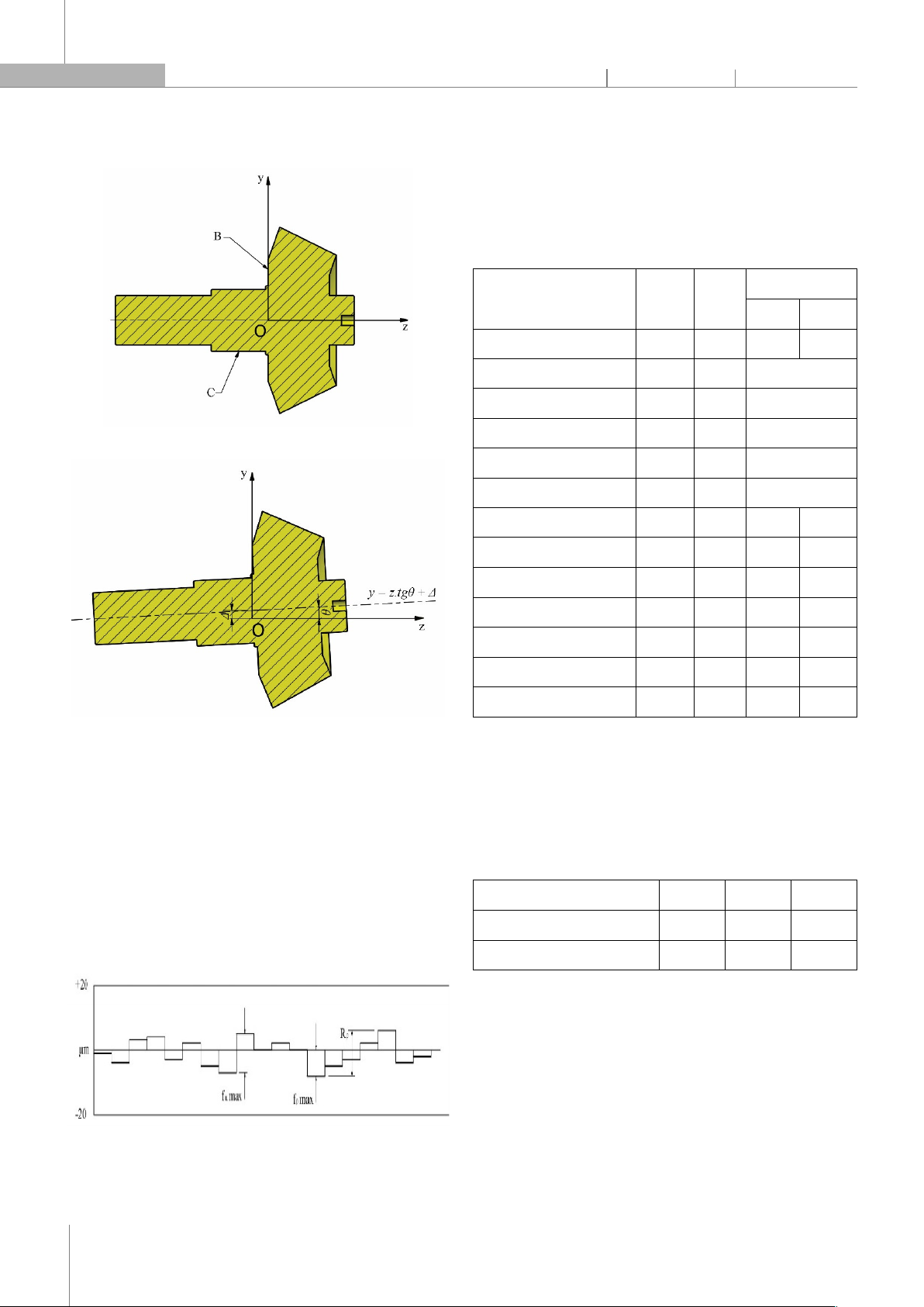
In the tooth cutting process, plane B and cylindrical
surface C are used to position the workpiece for
machining face-milled spiral bevel gear (Figure 2). The
plane B restricts three degrees of freedom (translating
motion along the z-axis rotary motion along the x and y
axes), and the cylindrical surface C restricts two more
degrees of freedom (translating motion along the x and y
axes). In the ideal case, plane B coincides with plane Oxy,
and the axis of cylindrical surface C coincides with the z-
axis of the machine. In reality, plane B is not entirely flat,
cylindrical surface C is not uniformly round, and the axis
of cylindrical surface C is not entirely perpendicular to
plane B. Therefore, positioning error can appear. Due to
the positioning error, the axis of the cylindrical surface C
will not coincide with the z-axis of the machine, as shown
in Figure 3. In this case, the general relationship of the axis
of the cylindrical surface C is described by equation (1):
y = z.tgθ + Δ (1)
CÔNG NGHỆ https://jst-haui.vn
Tạp chí Khoa học và Công nghệ Trường Đại học Công nghiệp Hà Nội Tập 60 - Số 11 (11/2024)
84
KHOA H
ỌC
P
-
ISSN 1859
-
3585
E
-
ISSN 2615
-
961
9
where Δ is the distance between the workpiece axis
and the z-axis of the machine-tool, and θ is the tilt angle.
Figure 2. Positioning the workpiece
Figure 3. Positioning error
In this paper, the influence of the parameters θ and Δ
on the indicators for evaluating tooth pitch errors,
including fp max - maximum single pitch deviation, fu max
- maximum difference between adjacent pitches, Fp -
total cumulative pitch deviation (Figure 4), was studied to
determine the maximum values of the parameters θ and
Δ so that the values of the indicators do not exceed 1/3
tolerance of DIN 6 accuracy level according to Standard
DIN 3965. From there, the machining accuracy level of the
workpiece positioning surfaces was requested.
Figure 4. Indicators for evaluating the tooth pitch errors
2. RESEARCH OBJECT AND METHOD
2.1. Research object
The research object in this paper is a pair of face-
milled spiral bevel gears designed according to standard
ISO 23509:2006 with parameters as shown in Table 1.
Table 1. Main geometrical parameters
Parameters Symbol Unit Value
Pinion Gear
Number of teeth Z 14 39
Mean normal module mmn mm 3.213
Angle of shaft axes Σ degree 90
Hypoid offset a mm 0
Face width b mm 25.4
Outer pitch cone distance Re mm 93.973
Mean normal pressure angle α degree 20 20
Mean spiral angle βm degree 35 35
Reference cone angle degree 19.747 70.253
Mean pitch diameter dm mm 54.918 152.987
Outer pitch diameter de mm 63.500 176.893
Outside tip circle diameter dae mm 75.324 178.288
Spiral direction Right Left
With the mean regular module in the range of
2 - 3.55mm and the outer pitch diameter of the pinion in
the range of 50 - 125mm, it is determined that the
tolerance of DIN 6 accuracy level for the indicators for
evaluating tooth pitch errors of the pinion is as shown
in Table 2.
Table 2. Tolerance for the indicators for evaluating tooth pitch errors
Indicators fp max fu max Fp
Tolerance (µm) 11 14 38
1/3 Tolerance (µm) 3.67 4.67 12.67
2.2. Research method
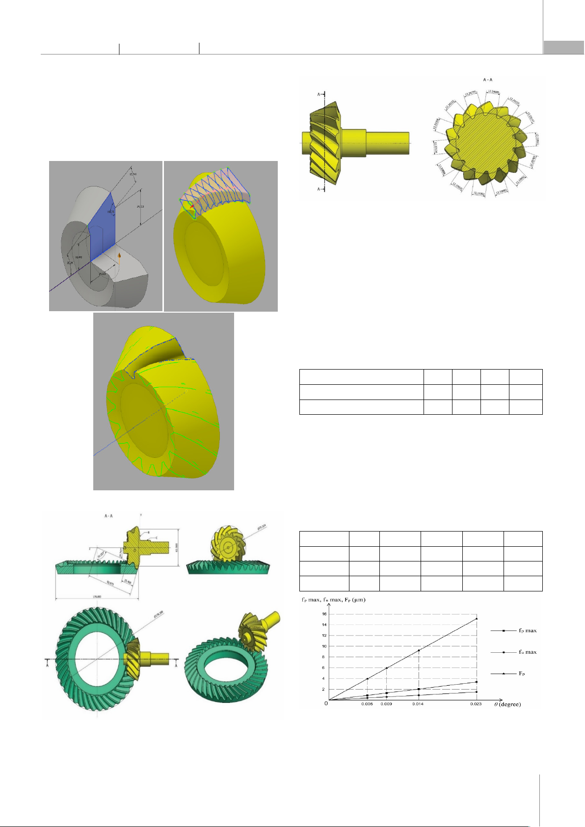
A 3D spiral bevel gear pair model was created in
Autodesk Inventor software, including three steps exactly
like the face-milled method (Figure 5). The drawing of the
final pinion and gear is shown in Figure 6.
To create positioning errors, when constructing the
sketch in step 1, the position of the rotation axis was
changed to not coincide with the coordinate axis (with
P-ISSN 1859-3585 E-ISSN 2615-9619 https://jst-haui.vn SCIENCE - TECHNOLOGY
Vol. 60 - No. 11 (Nov 2024) HaUI Journal of Science and Technology 85
the tilt angle θ and the distance Δ). By measuring the
length of chords on the mean pitch circle, as shown in
Figure 7, the tooth pitches were calculated, and then the
indicators fp max, fu max, and Fp were determined.
Changing the values of parameters θ and Δ will clarify the
influence of positioning error on tooth pitch errors.
Figure 5. Steps to create a 3D model
Figure 6. Drawing of the final pinion and gear
Figure 7. Measuring the length of chords on the mean pitch circle
3. RESULTS AND DISCUSSION
3.1. Influence of tilt angle on tooth pitch error
The main reason for the tilt angle θ is the non-
perpendicularity between plane B and the axis of
cylindrical surface C (Figure 2). Look up the
perpendicularity tolerance table to determine the
perpendicularity tolerance for each manufacturing
accuracy level, then calculate the tilt angle θ as shown in
Table 3.
Table 3. Tilt angle θ according to manufacturing accuracy level
Manufacturing accuracy level IT4 IT5 IT6 IT7
Perpendicularity tolerance (µm) 2.5 4 6 10
Tilt angle θ (degree) 0.006 0.009 0.014 0.023
When fixing Δ = 0 and changing θ according to the
values in Table 3, the results are determined as shown in
Table 4. Based on the results in Table 4, the influence
graphs of the tilt angle of workpiece axis to the z-axis of
the machine on the indicators for evaluating tooth pitch
errors were built, as shown in Figure 8.
Table 4. Result of determination of the influence of the tilt angle on the
indicators for evaluating tooth pitch errors
θ (degree) 0 0.006 0.009 0.014 0.023
fp max (µm) 0 0.880 1.320 2.052 3.369
fu max (µm) 0 0.392 0.587 0.914 1.501
Fp (µm) 0 3.954 5.928 9.219 15.135
Figure 8. The influence graphs of the tilt angle on the indicators for
evaluating tooth pitch errors
CÔNG NGHỆ https://jst-haui.vn
Tạp chí Khoa học và Công nghệ Trường Đại học Công nghiệp Hà Nội Tập 60 - Số 11 (11/2024)
86
KHOA H
ỌC
P
-
ISSN 1859
-
3585
E
-
ISSN 2615
-
961
9
As shown in Figure 8, it can be seen that the influence
graphs of the tilt angle of workpiece axis to the z-axis of
the machine on the indicators for evaluating tooth pitch
errors are all straight lines. It proves that all indicators for
evaluating tooth pitch error depend linearly on the tilt
angle. The mathematical equations of this dependence
are determined as follows:
fp max = 146.6*θ;
fu max = 65.28*θ;
Fp = 658.47*θ.
In which the indicators fp max, fu max, and Fp are
measured in micrometers, θ is measured in degrees.
Using these equations, the value of θ can be
determined so that the values of indicators do not exceed
1/3 of the tolerance of accuracy level DIN 6, as shown in
Table 2. For fp max ≤ 3.67µm, θ ≤ 0.025 is needed. For
fu max ≤ 4.67µm, θ ≤ 0.071 is needed. For Fp ≤ 12.67µm,
θ ≤ 0.019 is required.
Thus, for all values of the indicators for evaluating
tooth pitch errors not to exceed 1/3 of the tolerance of
DIN 6 accuracy level according to Standard DIN 3965, the
tilt angle of the workpiece axis to the z-axis of the
machine must not exceed 0.019 (equivalent to accuracy
level IT7).
3.2. Influence of distance on tooth pitch error
The distance between the workpiece axis and the z-
axis of the machine depends mainly on the roundness of
the cylindrical surface C. Given that the distance between
the axes is half the roundness tolerance of the cylindrical
surface C, determine the value of the distance between
the axes according to the manufacturing accuracy level,
as shown in Table 5.
Table 5. Distance between the axes Δ according to manufacturing
accuracy level
Manufacturing accuracy level IT4 IT5 IT6 IT7
Roundness tolerance (µm) 2.5 4 6 10
Distance between the axes Δ (µm) 1.25 2 3 5
Table 6. Result of determination of the influence of the distance between
the axes on the indicators for evaluating tooth pitch errors
Δ (µm) 0 1.25 2 3 5
fp max (µm) 0 0.817 1.308 1.962 3.270
fu max (µm) 0 0.364 0.583 0.873 1.456
Fp (µm) 0 3.674 5.878 8.817 14.695
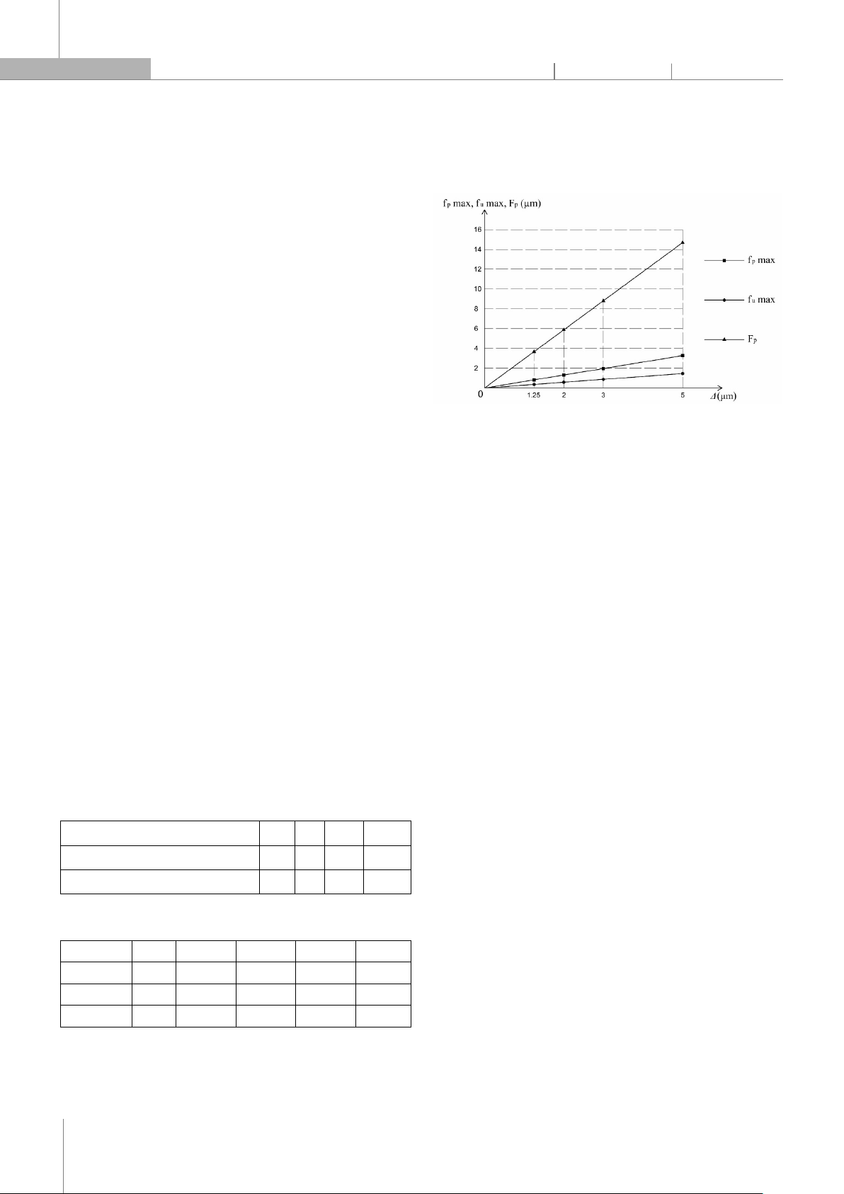
When fixing θ = 0 and changing Δ according to the
values in Table 5, the results are determined as shown in
Table 6. Based on the results in Table 6, the influence
graphs of the distance between the workpiece axis and
the z-axis of the machine on the indicators for evaluating
tooth pitch errors were built, as shown in Figure 9.
Figure 9. The influence graphs of the distance between the axes on the
indicators for evaluating tooth pitch errors
Similar to the dependence of the indicators for
evaluating tooth pitch error on tilt angle, the indicators
also depend linearly on the distance between axes. The
mathematical equations of this dependence are
determined as follows:
fp max = 0.654*Δ;
fu max = 0.291*Δ;
Fp = 2.939*Δ.
Using these equations, the value of b can be
determined so that the values of indicators do not exceed
1/3 of the tolerance of DIN 6 accuracy level, as shown in
Table 2. For fp max ≤ 3.67µm, Δ ≤ 5.61µm is needed. For fu
max ≤ 4.67µm, Δ ≤ 16.05µm is necessary. For Fp ≤
12.67µm, Δ ≤ 4.31µm is required.
Thus, for all values of the indicators for evaluating
tooth pitch errors not to exceed 1/3 of the tolerance of
DIN 6 accuracy level according to Standard DIN 3965, the
distance between the workpiece axis and the z-axis of the
machine must not exceed 4.31µm (equivalent to
accuracy level IT7).
3.3. The combined influence of tilt angle and distance
between axes on tooth pitch error
The results of determining the combined influence of
the tilt angle and the distance between axes on the
indicators for evaluating tooth pitch error are shown in
Table 7. Results of comparing the values of indicators for
evaluating tooth pitch errors due to the combined
influence of the tilt angle and the distance between the
axes with the corresponding values of these indicators due
to each individual influence as shown in Tables 8, 9, 10.


![Giáo trình Vật liệu cơ khí [mới nhất]](https://cdn.tailieu.vn/images/document/thumbnail/2025/20250909/oursky06/135x160/39741768921429.jpg)


