
REGULAR ARTICLE
Preliminary accident analysis of Flexblue
®
underwater reactor
Geoffrey Haratyk and Vincent Gourmel
*
DCNS, 143 bis, avenue de Verdun, 92442 Issy-les-Moulineaux, France
Received: 11 May 2015 / Received in final form: 8 September 2015 / Accepted: 17 September 2015
Published online: 05 December 2015
Abstract. Flexblue
®
is a subsea-based, transportable, small modular reactor delivering 160 MWe. Immersion
provides the reactor with an infinite heat sink –the ocean –around the metallic hull. The reference design includes
a loop-type PWR with two horizontal steam generators. The safety systems are designed to operate passively;
safety functions are fulfilled without operator action and external electrical input. Residual heat is removed
through four natural circulation loops: two primary heat exchangers immersed in safety tanks cooled by seawater
and two emergency condensers immersed in seawater. In case of a primary piping break, a two-train safety
injection system is actuated. Each train includes a core makeup tank, an accumulator and a safety tank at low
pressure. To assess the capability of these features to remove residual heat, the reactor and its safety systems have
been modelled using thermal-hydraulics code ATHLET with conservative assumptions. The results of simulated
transients for three typical PWR accidents are presented: a turbine trip with station blackout, a large break loss of
coolant accident and a small break loss of coolant accident. The analyses show that the safety criteria are
respected and that the reactor quickly reaches a safe shutdown state without operator action and external power.
1 Introduction
Flexblue
®
is a small modular reactor delivering 160 We to
the grid. The power plant is subsea-based (up to 100 m
depth and a few kilometres away from the shore) and
transportable. It is entirely manufactured in shipyard (no
large outdoor activities) and requires neither levelling nor
civil engineering work, making the final cost of the output
energy competitive. Thanks to these characteristics and its
small electrical output, Flexblue
®
makes the nuclear
energy more accessible for countries where regular large
land-based nuclear plants are not adapted, and where fossil-
fuelled units currently prevail on low-carbon solutions.
Immersion provides the reactor with an infinite heat sink
–the ocean –around the containment boundary, which is a
cylindrical metallic hull hosting the nuclear steam supply
systems (Tab. 1).
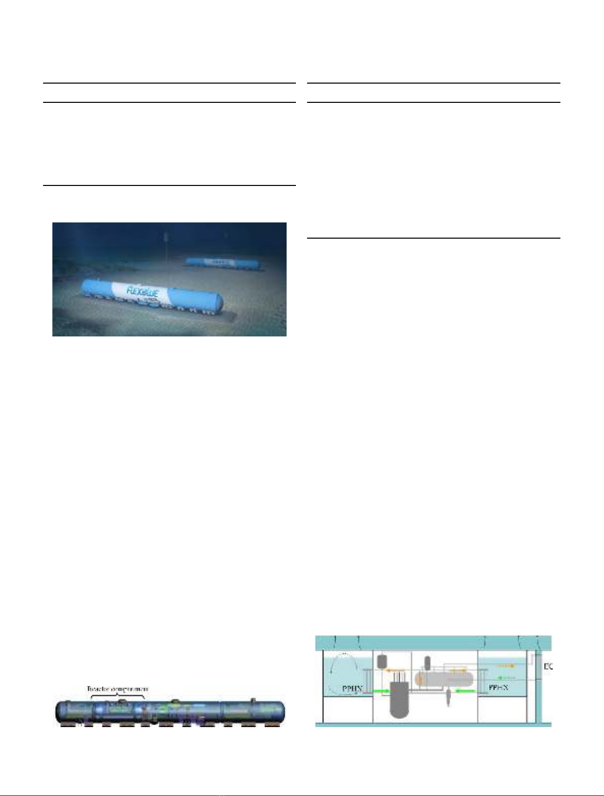
Several modules can be gathered into a single seabed
production farm and operate simultaneously (Fig. 1). The
reactor is meant to operate only when moored on the
seabed. Every three years, production stops and the module
is emerged and transported back to a coastal refuelling
facility, which hosts the fuel pool. This facility can be
shared between several Flexblue
®
modules and farms.
During operation, each module is monitored and possibly
controlled from an onshore control centre. Redundant
submarine cables convey both information and electricity
output to the shore. A complete description of the
Flexblue
®
concept, including market analysis, regulation
and public acceptance, security and environmental aspects,
is found in Haratyk et al. [1]. The purpose of this paper is to
present the first accident analysis of Flexblue
®
and to
discuss the performance of its innovative passive safety
systems.
2 The reactor and its safety features
2.1 The reactor
The reactor and all the nuclear systems carrying primary
coolant are hosted in one of the four watertight compart-
ments of the module (other compartments host the turbo
generator, an onboard control room, I&C control panels, a
living area and process auxiliaries) see Figure 2. The reactor
compartment boundary forms the third barrier of confine-
ment. The reference design of Flexblue
®
includes a loop-
type pressurized water reactor (PWR), with two horizontal
steam generators (SGs) and two motor coolant pumps. This
technology enjoys a long experience, both in civil power
production and in naval propulsion. Primary loops are
designed to ease natural circulation when coolant pumps
are turned off: pumps are plugged directly on steam
generators outlet in order to eliminate the usual U-shape
*e-mail: vincent.gourmel@dcnsgroup.com
EPJ Nuclear Sci. Technol. 1, 6 (2015)
©G. Haratyk and V. Gourmel, published by EDP Sciences, 2015
DOI: 10.1051/epjn/e2015-50030-x
Nuclear
Sciences
& Technologies
Available online at:
http://www.epj-n.org
This is an Open Access article distributed under the terms of the Creative Commons Attribution License (http://creativecommons.org/licenses/by/4.0),
which permits unrestricted use, distribution, and reproduction in any medium, provided the original work is properly cited.
pipe between SGs and pumps. The reactor core uses
classical fuel assembly technology: 17 17 fuel bundles
with an enrichment below 5%. Active length of the core is
2.15 m. Reactivity is controlled without soluble boron and
only with burnable poison and control rods. This feature is
very important because it allows major space savings (no
boron tank). The core design is deeply described in [2]
(Tab. 2).
2.2 The safety systems
The safety systems of Flexblue
®
are designed in order to
operate passively according to the IAEA passivity defini-
tion [3]. All safety functions are fulfilled without any
operator action and external electrical input. The little
amount of energy needed for actuation and monitoring is
supplied by onboard, redundant, rechargeable emergency
batteries featuring two weeks of autonomy.
Chain reaction can be stopped by two diversified
devices: the control rods and an emergency boron injection
system, which is actuated only in case of anticipated
transient without scram (ATWS). Both these devices can
independently shut down the reactor and keep it subcritical
up to cold shutdown state [2].
Residual heat removal is performed by four cooling
loops, each one able to remove 50% of decay heat:
–two primary chains are connected to the primary circuit:
each one includes an inlet pipe connected to a hot leg, a
heat exchanger (PPHX) immersed in a large safety water
tank, and an outlet pipe connected to a cold leg. The
intermediate heat sinks formed by the two safety tanks
are cooled by the ocean through the metallic hull;
–two secondary chains are connected to the secondary
circuit: each one includes an inlet pipe connected to a
main steam line, an emergency condenser directly
immersed in seawater and an outlet pipe connected to
a feedwater line.
Thanks to the infinite heat sink –seawater –and to the
elevation difference of the heat sink with respect to the heat
sources, the four chains operate passively by natural
circulation. In normal conditions operation, they are closed
by pneumatic valves and open to their fail-safe position
when electrical load is lost. The targeted long-term safe
state of the reactor is a shutdown state where continuous
cooling of the reactor core is achieved by natural circulation
(Fig. 3).
Protection against loss of coolant accidents is ensured
by two passive safety injection trains. Each one includes a
direct vessel injection (DVI) line fed by three injection
sources: a core makeup tank (CMT) pressurized by the
primary circuit, a classical accumulator pressurized at
50 bar by nitrogen and a large safety tank, which feeds the
primary circuit by gravity when primary pressure has
decreased to near containment pressure. In addition,
Fig. 2. Profile view of a Flexblue
®
module.
Table 1. Flexblue
®
module main characteristics.
Parameter Value
Unit power rating (MWe) 160
Length (m) 150
Diameter (m) 14
Immersion depth (m) 100
Fuel cycle length (months) 40
Lifetime (years) 60
Fig. 1. Artist view of a Flexblue
®
farm.
Table 2. Flexblue
®
reactor characteristics.
Parameter Value
Thermal power 530 MW
th
Reactor core 77 fuel assemblies
Fuel assembly 17 17 rods, 2.15 m high
Enrichment <5%
Average power density 70 kW/L
Hot rod peaking factor 2.26
Reactor coolant pressure 155 bar
DTcore 30 °C
Steam generators 2 recirculation SGs
SGs pressure 62 bar (saturated)
Fig. 3. Targeted safe state when primary circuit is intact.
2 G. Haratyk and V. Gourmel: EPJ Nuclear Sci. Technol. 1, 6 (2015)
a two-train automatic depressurization system (ADS) is
connected to the pressurizer (PZR) and to the hot legs to
generate a controlled depressurization of the primary
circuit, which enables faster injection. Once these systems
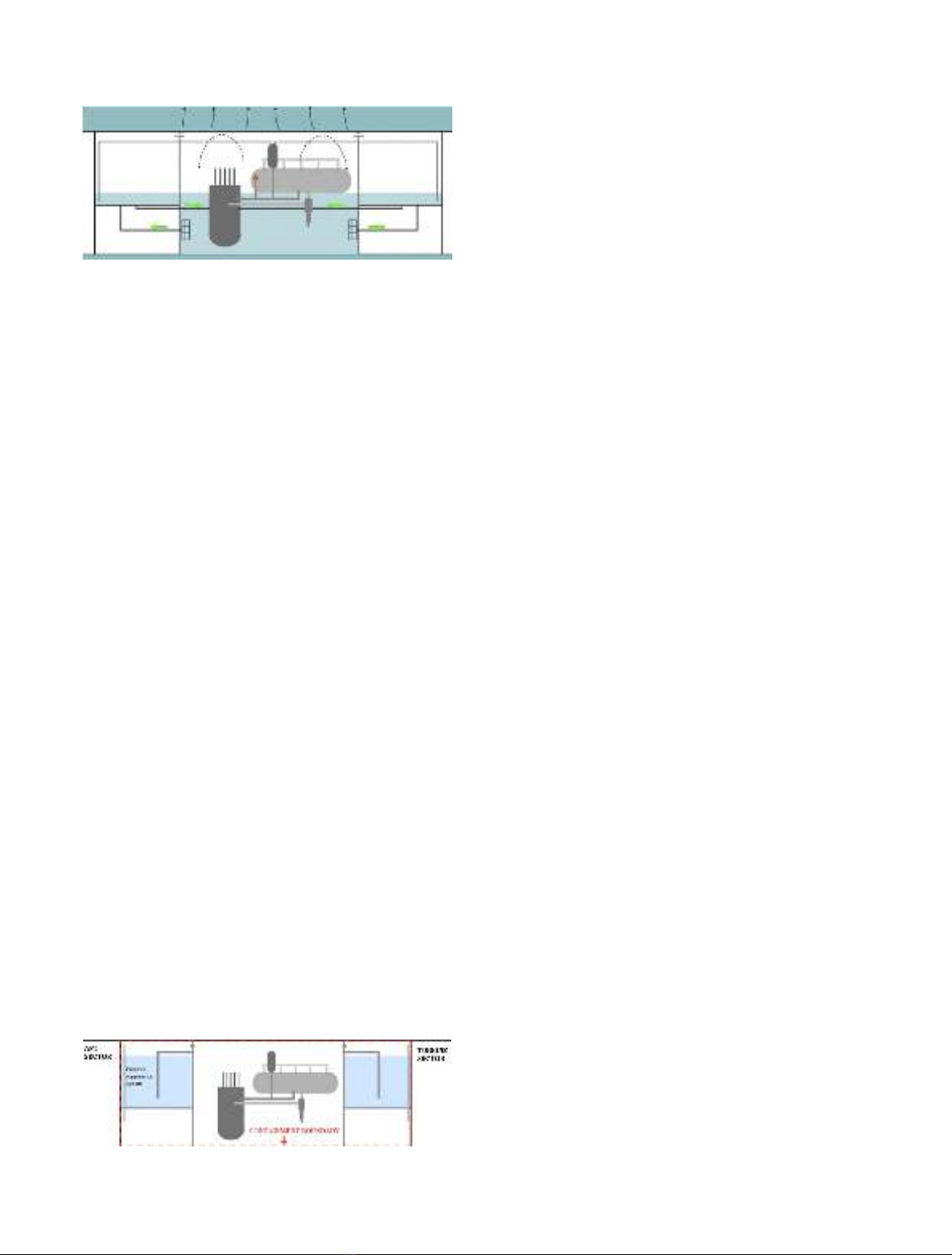
have actuated, the long-term equilibrium state is reached
when the safety tanks are empty and the reactor
compartment is flooded (Fig. 4). At that point, a passive
recirculation path is in place: water boils off the core, is
released in the containment, condensates on the contain-
ment walls, collects in the sump and is injected back into
the reactor pressure vessel through sump screens and DVI
lines by gravity. Decay heat is transported and removed
through the metallic hull. Thanks to the unlimited heat sink
(the ocean), grace period is theoretically infinite for both
targeted states, which is a breakthrough in nuclear safety.
The two large safety tanks not only play the two roles of
intermediate heat sinks and injection sources, but also a
third role of suppression pools –when a leak leads to a quick
containment pressurization. They also act as radiation
shield to protect workers and systems located in the
adjacent compartments. Confinement of the radioactive
isotopes is guaranteed by three hermetic barriers: fuel
cladding, primary circuit and containment boundary
formed by the hull and the compartment walls (Fig. 5).
The capability of the containment to reject decay heat to
seawater has been investigated by Santinello et al. [4].
Results show that the process is satisfactory and enables all
decay heat removal.
3 Analysis tool and reactor model
3.1 ATHLET
ATHLET (Analysis of Thermal-Hydraulics of LEaks and
Transients) is a thermal-hydraulic system code developed
by the German technical safety organization GRS. It is
applicable to the analysis of PWR and BWR, and has
already been used for the analysis of transients involving
horizontal SGs, similar to the ones of Flexblue
®
.Itis
composed of four main calculation modules: thermo-fluid
dynamics, heat transfer and heat conduction, neutron
kinetics, and control & balance of plant. ATHLET
validation work (including for passive systems) is presented
in [5].
3.2 Modelization
Flexblue
®
reactor is modelled (see Fig. 6) with ATHLET in
accordance with GRS guidelines [5,6]. The nodalization of
the circuits is performed in order to get both a sufficient
accuracy and an acceptable calculation time. Two core
channels are modelled: an outer ring and an inner channel
where power density is higher. In this latter one, the hot fuel
pin is modelled to calculate peak clad and fuel temper-
atures. The two loops are modelled, as well as all the safety
systems with the exception of the emergency boron
injection system (failure of scram is not considered in the
studied transients). Pressurizer and piping are considered
perfectly insulated. The injection sources (tanks and
accumulators) are not borated. The active auxiliary
systems and the regulations are not modelled. There are
three fluid dynamics systems in the model: the primary one
(primary circuit and connected systems), the secondary one
(secondary circuit and connected systems) and seawater.
The model considers a 2.5-second delay between the
scram signal and the full insertion of control rods. Decay
heat calculation is based on formulas from Todreas and
Kazimi [7], extracted from standards of American Nuclear
Society [8], and then conservatively increased by 20% to
respect NRC guidelines [9]. Figure 7 presents the considered
decay heat for the accident analyses.
4 Main hypotheses
Reactor core is at 100% of its nominal power (530 MW
th
)at
the beginning of each transient. The initiating event always
leads to a turbine trip (or is the turbine trip itself), which is
followed 3 s later by the loss of electrical load. The only
electrical sources available are the emergency batteries,
which are able to monitor and control the safety systems,
and to open or close some valves. The action of other active
components and systems is not considered. It is a
conservative assumption because the active systems would
only have a favourable effect in the performed transients. In
a future work, active systems will be modelled to study
more transients (for example, active injection should be
considered after a steam generator tube rupture).
The opening time of the valves is 2 s with the exception
of the ADS valves, which have a longer, preset opening
time. Pressurizer and steam generators safety valves
setpoints are respectively 171 bar and 83 bar, with a
one-second opening time. Even if it is planned to install flow
restrictors in the pipes, their effects are not taken into
account in the accident analysis, which is a conservative
measure. To provide a sufficient core flow when a pump
coast down happens, coolant pumps models include a
rotating inertia represented in Figure 8: the driving
Fig. 5. Limit of the containment boundary.
Fig. 4. Targeted safe state when primary circuit has failed.
G. Haratyk and V. Gourmel: EPJ Nuclear Sci. Technol. 1, 6 (2015) 3
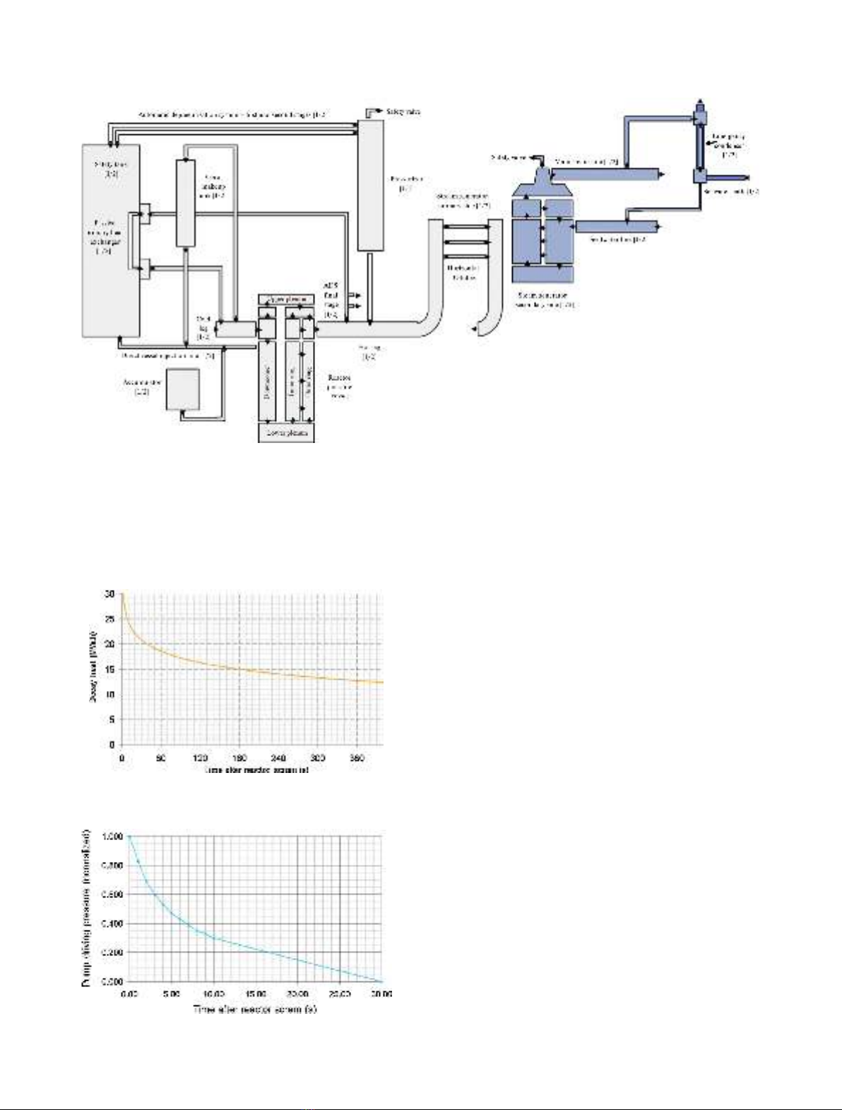
pressure reaches 50% of the nominal value after 5 s and 0%
after 30 s.
The containment pressure is set constant at 1 bar during
the transients, so the leak flow is maximized when a break
occurs. Heat sink temperature (seawater) is conservatively
set at 35 °C. Heat transfer between safety tanks and seawater
through the metallic hull is not modelled, which is
conservative. None of the steam generators tubes is
considered clogged. The detailed design of the Flexblue
®
core was not yet available when these analyses have been
conducted. As a consequence, the neutronic data of a typical
German Konvoi have been used. The conservative nature
of these input data is not established. As mentioned in
Section 8, core behaviour is to be watched closely with
accurate neutronic data when available. Average burn-up is
8.1 GWD/t and maximal burn-up is 45 GWD/t. The
actuation logic of emergency signals and passive systems
with the treatment delays considered are presented in
Table 3.
5 Turbine trip
The simulated transient starts with a turbine trip that
causes a loss of offsite power.
5.1 Results
The results are described in Table 4 and Figures 9–13.
5.2 Discussion
When turbine trip is triggered, steam and feedwater lines
are immediately closed (0.15 s). Reactor scram happens
more than 4 s later. During this time interval, primary and
secondary pressures strongly increase (Figs. 9 and 10)
because core is at full nominal power and heat is not
removed to any heat sink. After reactor scram, core power
Fig. 7. Decay heat of Flexblue
®
core.
Fig. 8. Coolant pumps driving pressure after reactor scram.
Fig. 6. ATHLET model. Dimensions are not representative. The model includes about 200 objects composed of about 1000 control
volumes.
4 G. Haratyk and V. Gourmel: EPJ Nuclear Sci. Technol. 1, 6 (2015)
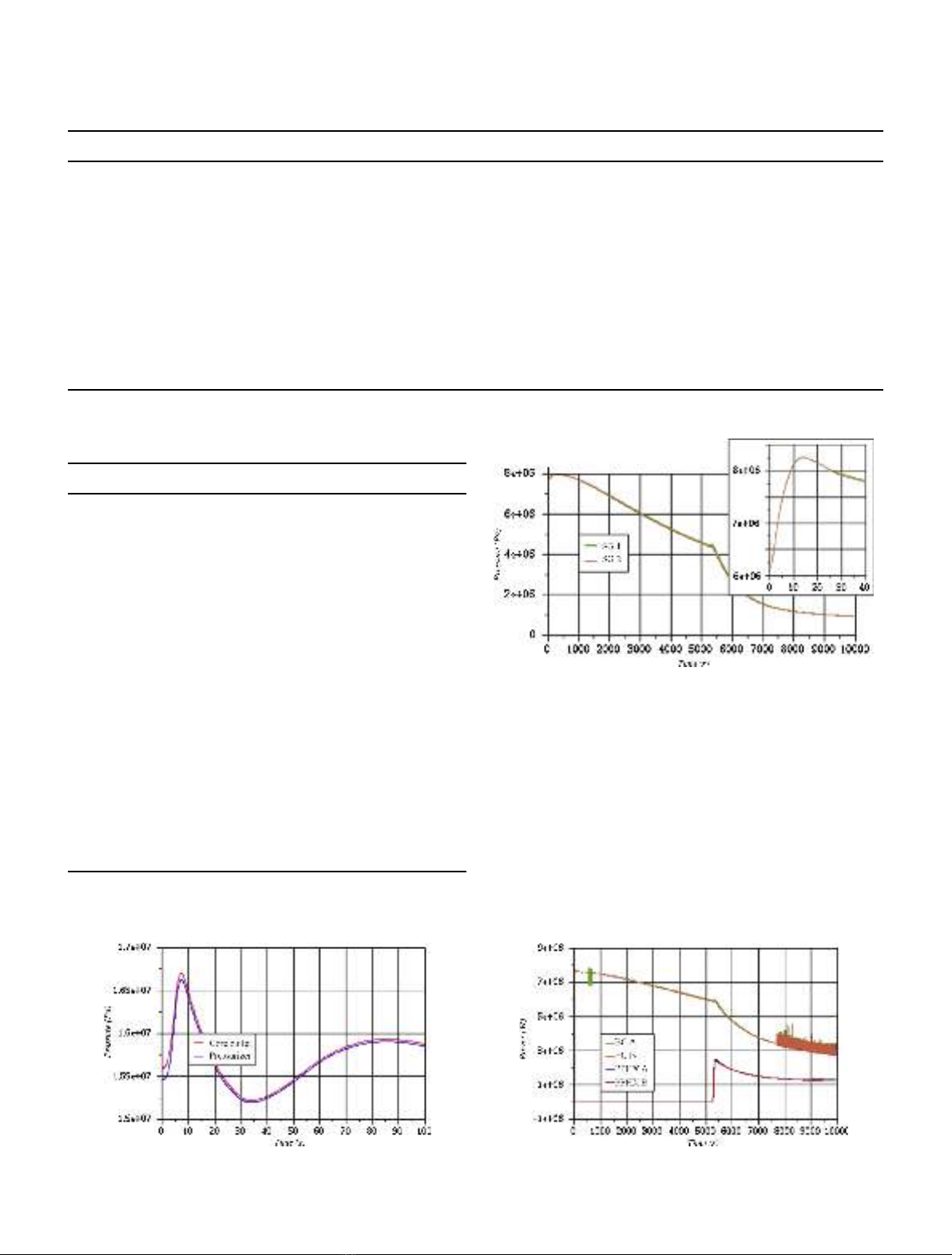
quickly decreases (Fig. 7) and high pressure in SGs leads to
the connection of both emergency condensers (ECs) that
transfer almost 16 MW
th
to seawater in the first minutes of
the transient (Fig. 11). Maximum primary conditions are
reached at t= 7.3 s (167 bar, 322 °C) and maximum
secondary conditions are reached 7 s later (82.7 bar,
298 °C). Both pressurizer pressure and SGs pressure remain
lower than their safety valves opening setpoints.
Concerning the boiling crisis risk in this transient, the
results provide a minimum departure of nucleate boiling
ratio (DNBR) of 3.87 at t= 3 s. Clad surface temperature
Table 3. Safety signals (conservative delays for actuation).
Signal Trigger(s) Delay (s)
Reactor protection High containment pressure or low pressurizer pressure 0.9
Reactor scram Reactor protection or low pump speed or high pressurizer pressure 1
Coolant pump stop Reactor protection or reactor scram or ADS first stage opening or
low pressurizer level
3
Feed and steam lines isolation Reactor protection or turbine trip 0.15
Core makeup tank injection Reactor protection or low pressurizer level 2
Emergency condensers actuation SG high pressure or passive primary cooling actuation 0.5
Passive primary cooling actuation CMT injection or high pressurizer level 4
ADS first stage opening CMT injection and low level in both CMTs 20
ADS second stage opening ADS first stage opening 70
ADS final stage opening ADS second stage opening and very low level in both CMTs 250
Table 4. Sequence of turbine trip accident.
Time Event
0 s Turbine trip
0.15 s Steam line and feedwater line isolation
3 s Station blackout. Coolant pumps coast down
with their inertia. Minimum DNBR is
reached (3.87)
4.6 s Reactor scram actuated by pumps low speed
6 s Emergency condensers are connected to SGs
7.3 s Maximum primary pressure and temperature
are reached (167 bar, 322 °C)
14 s Maximum secondary pressure and
temperature are reached (83 bar, 298 °C)
8 min Heat removed by ECs becomes greater than
heat removed by SGs which is greater than
decay heat
90 min Low pressurizer level leads to CMTs injection
and passive primary cooling actuation
100 min Primary temperature falls below 215 °C
150 min CMTs natural circulation stops
167 min End of simulation
Fig. 9. Primary pressure (Pa) during first 100 s.
Fig. 10. Secondary pressure (Pa) with focus on first 40 s.
Fig. 11. Emergency heat removal by ECs and PPHXs (W).
G. Haratyk and V. Gourmel: EPJ Nuclear Sci. Technol. 1, 6 (2015) 5


![Tài liệu học tập Hệ thống điều khiển điện - khí nén và thủy lực [mới nhất]](https://cdn.tailieu.vn/images/document/thumbnail/2021/20211005/conbongungoc09/135x160/811633401135.jpg)
![Tính chọn lắp ghép tiêu chuẩn giữa áo trục và trục chân vịt tàu thủy [chuẩn nhất]](https://cdn.tailieu.vn/images/document/thumbnail/2021/20210219/caygaocaolon10/135x160/5291613732560.jpg)


![Đề thi Kỹ thuật lập trình PLC: Tổng hợp [Năm]](https://cdn.tailieu.vn/images/document/thumbnail/2026/20260121/lionelmessi01/135x160/85491768986870.jpg)

![Đề thi cuối học kì 1 môn Máy và hệ thống điều khiển số năm 2025-2026 [Kèm đáp án chi tiết]](https://cdn.tailieu.vn/images/document/thumbnail/2025/20251117/dangnhuy09/135x160/4401768640586.jpg)


![Tự Động Hóa Thủy Khí: Nguyên Lý và Ứng Dụng [Chi Tiết]](https://cdn.tailieu.vn/images/document/thumbnail/2025/20250702/kexauxi10/135x160/27411767988161.jpg)


