
BioMed Central
Page 1 of 11
(page number not for citation purposes)
Head & Face Medicine
Open Access
Methodology
Feasibility of preoperative planning using anatomical facsimile
models for mandibular reconstruction
Corrado Toro*1, Massimo Robiony†1, Fabio Costa†1, Nicoletta Zerman†2 and
Massimo Politi†1
Address: 1Department of Maxillofacial Surgery, University of Udine, Udine, Italy and 2Institute of Oral Pathology, University of Ferrara, Ferrara,
Italy
Email: Corrado Toro* - corrado.toro@poste.it; Massimo Robiony - massimo.robiony@med.uniud.it; Fabio Costa - maxil2@med.uniud.it;
Nicoletta Zerman - maxil1@med.uniud.it; Massimo Politi - m.politi@med.uniud.it
* Corresponding author †Equal contributors
Abstract
Background: Functional and aesthetic mandibular reconstruction after ablative tumor
surgery continues to be a challenge even after the introduction of microvascular bone
transfer. Complex microvascular reconstruction of the resection site requires accurate
preoperative planning. In the recent past, bone graft and fixation plates had to be reshaped
during the operation by trial and error, often a time-consuming procedure. This paper
outlines the possibilities and advantages of the clinical application of anatomical facsimile
models in the preoperative planning of complex mandibular reconstructions after tumor
resections.
Methods: From 2003 to 2005, in the Department of Maxillofacial Surgery of the University
of Udine, a protocol was applied with the preoperative realization of stereolithographic
models for all the patients who underwent mandibular reconstruction with microvascular
flaps. 24 stereolithographic models were realized prior to surgery before
emimandibulectomy or segmental mandibulectomy. The titanium plates to be used for
fixation were chosen and bent on the model preoperatively. The geometrical information
of the virtual mandibular resections and of the stereolithographic models were used to
choose the ideal flap and to contour the flap into an ideal neomandible when it was still
pedicled before harvesting.
Results: Good functional and aesthetic results were achieved. The surgical time was
decreased on average by about 1.5 hours compared to the same surgical kind of procedures
performed, in the same institution by the same surgical team, without the aforesaid protocol
of planning.
Conclusion: Producing virtual and stereolithographic models, and using them for
preoperative planning substantially reduces operative time and difficulty of the operation
during microvascular reconstruction of the mandible.
Published: 15 January 2007
Head & Face Medicine 2007, 3:5 doi:10.1186/1746-160X-3-5
Received: 09 August 2006
Accepted: 15 January 2007
This article is available from: http://www.head-face-med.com/content/3/1/5
© 2007 Toro et al; licensee BioMed Central Ltd.
This is an Open Access article distributed under the terms of the Creative Commons Attribution License (http://creativecommons.org/licenses/by/2.0),
which permits unrestricted use, distribution, and reproduction in any medium, provided the original work is properly cited.

Head & Face Medicine 2007, 3:5 http://www.head-face-med.com/content/3/1/5
Page 2 of 11
(page number not for citation purposes)
Background
Medical rapid prototyping (MRP) is defined as the manu-
facture of dimensionally accurate physical models of
human anatomy derived from medical image data using a
variety of rapid prototyping (RP) technologies [1]. It has
been applied to a range of medical specialties, including
oral and maxillofacial surgery.
MRP was described originally by Mankowich et al in 1990
[2]. The development of the technique has been facilitated
by improvements in medical imaging technology, compu-
ter hardware, three-dimensional image processing soft-
ware, and the technology transfer of engineering methods
into the field of surgery.
By using three-dimensional imaging a vast number of
complex slice images can be quickly appreciated. The term
'three-dimensional', however, is not a truly accurate
description of these images as they are still displayed on a
radiological film or flat screen in only two dimensions.
Computed Tomography offers volumetric information,
which can be translated in three dimensional models.
These models can be visualized but also exported to RP
systems, that can produce these structures thanks to the
rapidity and versatility of the technologies involved.
After resection of the mandible, reconstruction using a
free vascularized bone graft has become the predominant
treatment of choice [3].
Functional and aesthetic mandibular reconstruction after
ablative tumor surgery continues to be a challenge even
after the introduction of microvascular bone transfer.
One of the goals of mandibular reconstruction after
tumor resection is a return to premorbid form and func-
tion. Complex microvascular reconstruction of the resec-
tion site requires accurate preoperative planning.
Otherwise, postoperative surgical outcome often results in
inadequate three dimensional mandibular shape and pro-
jection as well as disturbed function, thereby affecting the
patient's quality of life [4].
Continuity defects created in the facial skeleton often
result with treatment of certain pathologic conditions,
most notably tumor ablation, osteoradionecrosis, and
refractory osteomyelitis. The reconstruction of the mandi-
ble keeps being complicated for the maxillofacial surgeon,
because functional and aesthetical properties must be
accurately re-established. The bone graft must be the exact
size and dimension of the defect, to assure a precise three-
dimensional configuration of the mandible.
It is necessary to know the three-dimensional configura-
tion of the mandibular defect, in order to choose the best
donor site, and to prepare fixation rigid enough to with-
stand masticatory force.
Previously, the bone graft and the fixation plates had to be
reshaped during the operation by trial and error, often a
time-consuming procedure.
In these contexts, the availability of a copy of the real anat-
omy allows not only a planning but also, with the limita-
tions due to the materials, a practical execution of the
surgical operation. Nevertheless, the RP model presents
also some disadvantages that can be reduced if the practi-
cal simulation is accompanied by a virtual simulation,
performed on a digital model.
This paper outlines the possibilities and advantages of the
clinical application of anatomical facsimile models in the
preoperative planning of complex mandibular reconstruc-
tions after tumor resections.
Methods
From 2003 to 2005, in the Department of Maxillofacial
Surgery of the University of Udine, an operative protocol
was applied with the preoperative realization of stereo-
lithographic models for all the patients who underwent
mandibular reconstruction with microvascular flap.
24 models were realized prior to surgery before emimand-
ibulectomy or segmental mandibulectomy. The diagnoses
were: squamous cell carcinoma (12 cases), ameloblast-
oma (9 cases), myxofibroma (1 case), aggressive juvenile
ossifying fibroma (1 case), osteosarcoma (1 case).
The data acquisition has been performed using Computer
Tomography (CT), the 3D model has been the result of
Reverse Engineering (RE) practices based on image seg-
mentation, and the real model has been produced using a
RP technology called Stereolithography [5,6].
The digital data of the virtual reality were employed in the
diagnostic phase and for the preliminary surgical plan-
ning. Moreover, virtual simulations on the 3D model
have been obtained from image segmentation.
Data acquisition was performed by helical CT scanner sin-
gle-slice Toshiba Asteion, or by four rowmultislice helical
CT scanner Toshiba Aquilion.
The result of the CT, a sequence of gray images, constitutes
the input, expressed in the form of raw data, for the RE
activities, with the help of dedicated commercial software
packages.
In the sequence of images representing the various sec-
tions, the anatomical structures can be identified on the

Head & Face Medicine 2007, 3:5 http://www.head-face-med.com/content/3/1/5
Page 3 of 11
(page number not for citation purposes)
basis of the gray level of the pixels. These anatomical
regions are contoured using segmentation algorithms,
and the three dimensional structure is reconstructed by
generating skinning surfaces that join the resulting pro-
files. The surface representing the 3D model is described
by way of a triangle mesh; this representation can be easily
transferred to a Rapid Prototyping laboratory.
Stereolithography uses a liquid resin which is polymer-
ized, layer by layer, by a UV laser beam which solidifies
the region representing the area of the section. The part is
built inside a vat full of liquid resin. When the building
process is finished, the part is drained, the supports,
which allowed the production of hanging parts, are easily
removed and the polymerization is completed in a UV
oven [7].
During the discussions with the surgeons the need for the
simulation of the surgical procedure has been perceived
not only on the model obtained from RP, but also on a
digital model in a virtual context. In fact, from the first
experiences with RP models, our surgical team appreci-
ated the help obtainable from them, but underlined also
their limitations, with particular accent on the fact that,
once cut and manipulated, the stereolithography model is
almost unusable. Therefore, it was necessary to find a
method for simulating the surgical procedure on the vir-
tual 3D model we had at our disposal. This model, repre-
senting the anatomical context relatively to the bone
tissues, was available in the STL format generated by the
image segmentation software. We used the software Magic
STL Fix (V6.3.3.0 – Cimatron Ltd. Materialize N.V. – US)
on an operating system MS Windows 2000.
The construction of the resin model begins by gathering
data slices of 1 mm from CT scans. CT data are transferred
to the Stereolithography machine (SLA 3500 – 3D Sys-
tems – Valencia, USA). Model fabrication starts with a
tank full of liquid plastic and the data controlling compu-
ter. The platform is immersed in the liquid plastic and
then raised to a level just below the surface of the viscous
liquid photopolymer (Epoxy resin Watershed 11120 –
DSM – Heerlen, NL). When a software-guided beam from
a helium-cadmium laser strikes the surface of the liquid
through a small series of adjustments, the plastic solidi-
fies. After the first layer has been built, the platform lowers
slightly in the tank and then is raised again. The guided
laser once again strikes the liquid and polymerizes it. The
dipping process is repeated to allow the layers to fuse.
Each layer is polymerized at a thickness of approximately
0.125 mm [8]. Precise control of the movement of the
platform, the viscosity of the liquid, and the position of
the laser cause the solid plastic ridge to adhere to the plat-
form. Once the model has been built, it is moved to an
ultraviolet (UV) oven for postcuring. This design process
can produce a 40-g resin replica in approximately 10
hours.
The titanium plates to be used for fixation were chosen
and bent on the stereolithographic models preoperatively.
The data of the virtual resected mandibles were used to
calculate the ideal position and angulation of osteotomies
of the microvascular flaps in the three planes (x, y, z) to
create an ideal "best-fit" of the neomandibles into the
resection sites.
The geometrical information of the virtual mandibular
resections and of the stereolithographic models was used
to choose the ideal flap and to contour the flap into an
ideal neomandible when it was still pedicled before har-
vesting. The preformed microvascular bone was then tras-
ferred to the resection site without further osteotomy.
24 microvascular flaps were employed for the reconstruc-
tions: 19 iliac free flaps and 5 fibular free flaps.
All the operations were performed by the same double
surgical team (contemporary mandibular resection and
flap raising).
Orthopantomographies were performed immediately
after surgery, at the end of the bone consolidation period
(3 months after surgery), and at the time of the removal of
the fixation plates (6 months after surgery).
Case Presentations
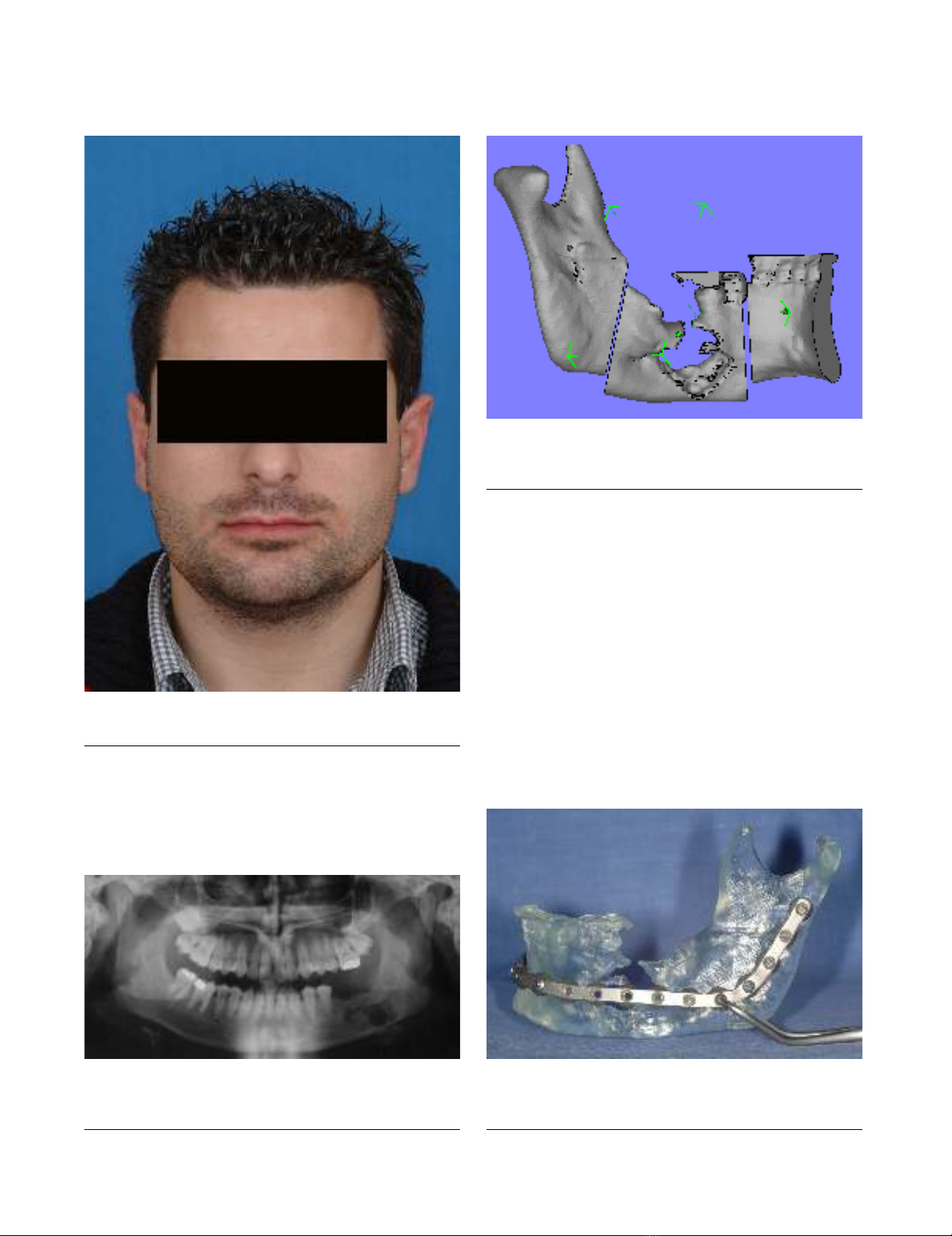
Case 1
A 28-year-old man was referred to our Clinic for treatment
of a recurrence of ameloblastoma, previously treated in
another institution (Fig. 1). Panoramic radiograph
showed a multiloculated lesion on the left mandibular
body (Fig. 2). The surgical procedure was first planned on
the virtual digital model (Fig. 3), it helped us to measure
exactly and to visualize the entity of the resection. A stere-
olithographic model of the left mandible was constructed.
Prior to surgery, a mandibular reconstruction plate was
pre-bent using the stereolithographic model as a refer-
ence. Screw placement was also planned and marked on
the model, as well as screws length, which were recorded
by measuring the thickness of the model at each plate hole
(Fig. 4).
The focus of the treatment was to resect the tumor and
preserve the form of the mandible. Before resection, the
reconstruction plate was placed intraorally along the infe-
rior border of the mandible, and screw holes were drilled
to facilitate later fixation of the plate. The time spent in
adapting the reconstruction plate was less than 5 minutes
because no adjustments to the plate were necessary.
Head & Face Medicine 2007, 3:5 http://www.head-face-med.com/content/3/1/5
Page 4 of 11
(page number not for citation purposes)
stereolithographic model and prebent reconstruction plate with adequate extension beyond area of projected resectionFigure 4
stereolithographic model and prebent reconstruction plate
with adequate extension beyond area of projected resection.
panoramic radiograph showing left mandibular lesion in patient n°1Figure 2
panoramic radiograph showing left mandibular lesion in
patient n°1.
preoperative view of the patient n°1Figure 1
preoperative view of the patient n°1.
preoperative planning of the surgical resection on virtual reality with CAD softwareFigure 3
preoperative planning of the surgical resection on virtual
reality with CAD software.
Head & Face Medicine 2007, 3:5 http://www.head-face-med.com/content/3/1/5
Page 5 of 11
(page number not for citation purposes)
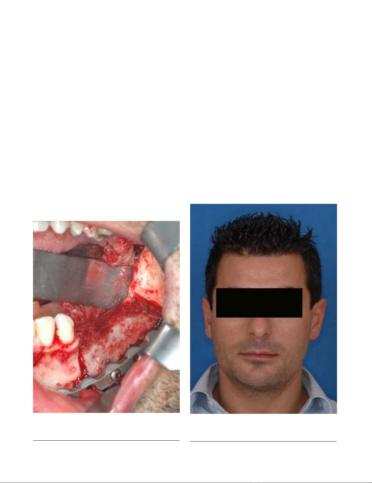
The iliac microvascular flap was harvested and modelled
using the dimensional data recorded during the preopera-
tive planning on the digital model and on the stereolitho-
graphic model. The insertion of the flap in the osseus gap
was easy and with excellent fit (Fig. 5). 6 months after the
reconstruction, the plate was removed and implants were
inserted (Fig. 6, 7, 8).
Case 2
The patient was a 50-year-old man who had a T4N0M0
squamous-cell carcinoma of the gingiva invading the left
mandible (Fig 9, 10, 11). The planning was made accord-
ing to the aforementioned protocol (Fig. 12, 13).
Reconstruction was planned with a iliac microvascular
osteo-muscolar flap with the use of a portion of the inter-
nal oblique muscle for the reconstruction of the intraoral
mucosa. The resected specimen included the left mandi-
ble from premolars to the entire ramus, saving the con-
dyle. The reconstruction plate was then placed; no intra-
operative modifications were necessary (Fig. 14, 15).
There were no signs of recurrence 1 year after surgery. The
plate could be removed and the reconstruction appeared
suitable for the use of bone-integrated dental implants
(Fig. 16, 17, 18).
Results
In all patients the intraoperative situation corresponded
to the stereolithographic model.
The virtual and model planning acted as a guide to the
length, the shape (in particular the mandibular angle), the
height as well as the contour of the bone graft, thus mini-
mizing the number of osteotomies.
There were 2 fibular flaps reexplorations, with 1 salvage
and 1 failure (bone initially sectioned into 3 fragments),
yielding an overall flap success rate of 95.8% (23 of 24).
Clinically and radiographically, there was nearly perfect
symmetry of the reconstructed mandibles and undis-
turbed bone healing of the 23 survived flaps.
postoperative clinical view of the patient n°1, six months after surgeryFigure 6
postoperative clinical view of the patient n°1, six months
after surgery.
intraoperative view after the fixation of the microvascular iliac flap with the prebent plateFigure 5
intraoperative view after the fixation of the microvascular
iliac flap with the prebent plate.