
Engineering Solid Mechanics 3 (2015) 195-206
Contents lists available at GrowingScience
Engineering Solid Mechanics
homepage: www.GrowingScience.com/esm
The influence of cutting conditions and cutting tool geometry on the atomistic
modeling of precision cutting
Angelos P. Markopoulos*, Nikolaos E. Karkalos, Kalliopi-Artemi L. Kalteremidou, Andreas
Balafoutis and Dimitrios E. Manolakos
Section of Manufacturing Technology, School of Mechanical Engineering, National Technical University of Athens, Heroon Politechniou 9, 15780,
Athens, Greece
A R T I C L E I N F O A B S T R A C T
Article history:
Received 6 January, 2015
Accepted 3 April 2015
Available online
3 April 2015
In this paper a molecular dynamics simulation of nano-metric cutting of copper with a diamond
tool is presented. MD simulations require the determination of the interaction of the involved
atoms through a function of potential for the materials involved in the analysis and the accurate
topography of the studied area, leading to high demand of computational time. The models
presented are taking into account the cubic lattice of copper, test two different potential
functions and at the same time control the computational cost by introducing small models at
realistic cutting conditions. This is realized by a novel code developed and allows focusing on
the influence of several processes and modeling parameters on the outcome of the simulations.
Models with and without thermostat atoms are investigated and the influence of cutting
conditions and cutting tool geometry on chip morphology, cutting forces and cutting
temperatures are studied.
© 2015 Growing Science Ltd. All rights reserved.
Keywords:
Molecular dynamics
Simulation
Nano-machining
Cutting forces
Morse potential
1. Introduction
Nanotechnology is considered nowadays one of the most technologically advanced scientific
fields. Several applications of nanotechnology are already included both in special and everyday
products and the interest in further developing this modern field of science is increasing. As far as nano-
scale manufacturing processes are concerned, the thorough understanding of the parameters of these
processes and the physical mechanisms involved are needed in order to increase their efficiency and
capabilities. Considering that the amount of experimental data and the capabilities of measurement
techniques are nowadays rather insufficient, numerical methods have been developed for the
investigation of nano-machining processes. Perhaps the most used method for modeling manufacturing
processes is the Finite Elements Method (FEM) (Markopoulos, 2013). More specifically, in the field of
micromachining, several works pertaining to FEM simulations have already been published; a review
* Corresponding author. Tel : +302107724299
E-mail addresses: amark@mail.ntua.gr (A. P. Markopoulos)
© 2015 Growing Science Ltd. All rights reserved.
doi: 10.5267/j.esm.2015.4.001

196
can be found in (Markopoulos and Manolakos, 2014). However, the Molecular Dynamics (MD) method
is one of the most used numerical methods in nano-scale simulations. It is considered more appropriate
than other numerical methods which have been used for machining process simulations, as macro-scale
methods include the assumption of a continuum; in nano-scale this assumption is not helpful and instead
a proper modeling of inter-atomic forces is required. Although MD method was developed over six
decades ago for general atomistic simulations (Metropolis et al., 1953; Alder and Wainwright, 1957),
it is currently used in many engineering fields. MD is also applied to simulate several precision
manufacturing processes and nano-scale cutting (Komanduri and Raff, 2001; Oluwajobi and Chen,
2010).
Early MD simulations in nano-cutting processes were carried out by Belak and Stowers (1990) and
Belak et al. (1993), who investigated the nano-cutting process of copper and silicon both for 2D and
3D configurations for several depths of cut and rake angles. Later, Ikawa et al. (1991) studied the effect
of the minimum depth of cut and the ratio of the depth of cut to the radius of curvature in the specific
cutting energy, the surface deformation and the chip formation mechanism. Inamura et al. (1992)
presented a model for the transformation of an atomistic model to an equivalent continuum model for
the nano-cutting process. Maekawa and Itoh (1995) studied the effect of friction between a copper
workpiece and a diamond cutting tool. Kim and Moon (1995) studied the cutting mechanism of copper
and aluminum using a 2D model and Morse potential and investigated the behavior of each material in
two different depths of cut and cutting speeds. Komanduri et al. (1998) conducted simulations on ultra
high precision cutting processes, investigated the effect of the cutting tool shape in this process and
also (Komanduri et al., 2000) investigated the effect of the crystal direction, the cutting direction and
the rake angle in an aluminum nano-cutting simulation. Ye et al. (2003) carried out simulations with
large negative rake angle values and a copper cutting tool in a copper workpiece nano-cutting process.
They investigated the effect of different cutting speeds in the chip forming mechanism and machined
surface quality. Furthermore, Pei et al. (2006) investigated the effect of potential function on the cutting
forces during nano-cutting.
As the influence of the temperature during the cutting process is significant in every scale of
simulation, several efforts to include a proper temperature calculation in MD nano-cutting simulations
have to date been made. Rentsch and Inasaki (1994) included a model for temperature regulation in
their study concerning ultra high precision cutting processes. Isono and Tanaka (1997) studied the effect
of workpiece temperature in the nano-cutting mechanism and surface roughness. Cai et al. (2007)
studied the temperature field in a silicon workpiece nano-cutting process. Dziedzic et al. (2008)
included a Nosé-Hoover thermostat model in a study of the cutting tool degradation and were able to
predict the local temperature fields in their system. Romero et al. (2013) analyzed the temperatures
profile and the thermal phenomena occurring in a nano-cutting machining process, using a classic
orthogonal cutting model. Romero et al. (2014) also integrated a thermostat model in an MD study of
tribological shearing. Furthermore, Zhu et al. (2014) carried out simulations of copper nano-cutting
process and investigated the effect of the temperature of the workpiece on the cutting forces. Li et al.
(2015) studied the effect of the grinding speed in the temperature profile.
In this study, several investigations regarding nano-machining processes using the MD method are
conducted. The effect of a variety of machining parameters proven to be of major importance also in
conventional cutting process such as depth of cut, cutting tool speed, cutting tool shape and rake angle
are examined using an orthogonal nano-scale model. Furthermore, the effect of the use of temperature
boundary conditions in the MD model by adding thermostat atoms to the model is also investigated in
several cases.
2. The Molecular Dynamics method
The basic aspects of the Molecular Dynamics method are the equation of motion, the potential
function, the inter-atomic forces calculation, the numerical time integration of the equation of motion
using appropriate numerical schemes and the boundary conditions. Potential functions such as Lennard-
Jones or Morse potential function are used for the calculation of the inter-atomic forces. The choice of

A. P. Markopoulos et al. / Engineering Solid Mechanics 3 (2015)
197
the appropriate potential function is crucial as each potential is often more suitable for a certain category
of materials whose nano-scale behavior it can simulate to a sufficient degree. Complex potential
functions, such as the embedded-atom model (EAM) potential, are also extensively used in MD
simulations but often, simpler and less time consuming potentials can also produce sufficiently accurate
results.
The Lennard-Jones potential is suitable for those metals whose behavior can be described using
the so-called “hard-sphere model”. The “6-12” formulation of the Lennard-Jones potential that is often
used is expressed as:
𝑉𝑉𝑖𝑖𝑖𝑖 = 4𝜀𝜀��𝜎𝜎
𝑟𝑟�12 −�𝜎𝜎
𝑟𝑟�6�
(1)
where ε is the depth of the potential well, σ is the distance at which the inter-particle potential is zero
and r is the distance between two atoms. The Morse potential is also appropriate for simulations of fcc
metals and is frequently used in MD simulations due to its relatively low computational cost. The
formula for the Morse potential is given by:
𝑉𝑉𝑖𝑖𝑖𝑖 =𝐷𝐷(𝑒𝑒−2𝑎𝑎�𝑟𝑟𝑖𝑖𝑖𝑖−𝑟𝑟𝑒𝑒�−2𝑒𝑒−𝑎𝑎�𝑟𝑟𝑖𝑖𝑖𝑖−𝑟𝑟𝑒𝑒�)
(2)
where rij is the distance between the atoms i and j, re is the equilibrium bond distance, D is the well
depth and the parameter a is related to the ‘width’ of the potential function and controls the magnitude
of the potential well. Parameters D and a have the dimensions of reciprocal distance and energy,
respectively. The equation of motion is solved in order to calculate the displacement, velocity and
acceleration of each atom in the study. Using the potential function, the forces exerted on each atom
can be calculated by differentiating the potential energy function and then used in the differential
equation system, e.g. the Newton equations of motion, to calculate the displacement, velocity and
acceleration of atoms.
There are three main methods for the calculation of atomic interactions (Rapaport, 2004): the all-
pairs method, the cell subdivision method and the neighbor-list method. These methods are used to find
which atoms are to be included in the inter-atomic forces calculation and often constitute the most time-
consuming part of an MD code.
An appropriate numeric time integration scheme is required to be chosen for the time integration
of the equation of motion. The key factor in this choice is that the method should not require the
calculation of inter-atomic forces multiple times in each time step, leading to a rather inefficient code
in connection to the computational time required, unless the accuracy of the results is radically
improved. The most preferable integration schemes in MD simulations are the Verlet algorithm, the
Leapfrog method and predictor-corrector schemes.
Eventually, the choice of the initial and boundary conditions is equally decisive for an MD
simulation. The structure of each material present in the simulation, i.e. fcc or bcc lattice, must be
properly defined as well as the initial velocity and acceleration for each atom. The choice of the initial
velocities in the system is performed in regard to the conservation of the total momentum in the system.
In MD nano-cutting simulations two basic categories of boundary conditions are often imposed:
boundary conditions on the motion of atoms of the workpiece and boundary conditions for the
regulation of temperature in the workpiece and sometimes in the cutting tool. Several methodologies
for the regulation of the temperature are used in MD, namely Berendsen algorithm, Velocity rescaling,
Nosé-Hoover algorithm just to name some. These algorithms differ in the way they enable the
adjustment of the temperature to the desired temperature.
3. Simulation parameters
An orthogonal nano-cutting model is used in every simulation in this paper. The main parameters
used in each simulation are presented in Table 1 and shortly described afterwards. The simulations were
carried out with a generic in-house Molecular Dynamics software.
198
Table 1. Simulation parameters
Configuration
2D-cutting
Potential function
Lennard-Jones, Morse Potential
Workpiece dimensions (Å)
143 x 35
Workpiece material
Copper (fcc)
Number of workpiece atoms
Cases without thermostats
Cases with thermostats
684 (Newtonian)
576 (Newtonian)
116 (boundary)
116 (boundary)
108 (thermostats)
Tool dimensions (Å)
60.06 x3.08
Number of tool atoms
120, 240 (in some cases)
Tool material
Diamond (supposed C)
Tool edge
sharp
Tool rake angle (degrees)
0,10,20,30
Depth of cut (Å)
8,10,12,14,15,20,30
Cutting speed (m/s)
123,246
Cutting direction
-x
Bulk temperature (K)
293
Integration scheme
Leapfrog
Integration time step (fs)
10
Total simulation time
Varying according to the cutting speed
Total cutting length (Å)
130
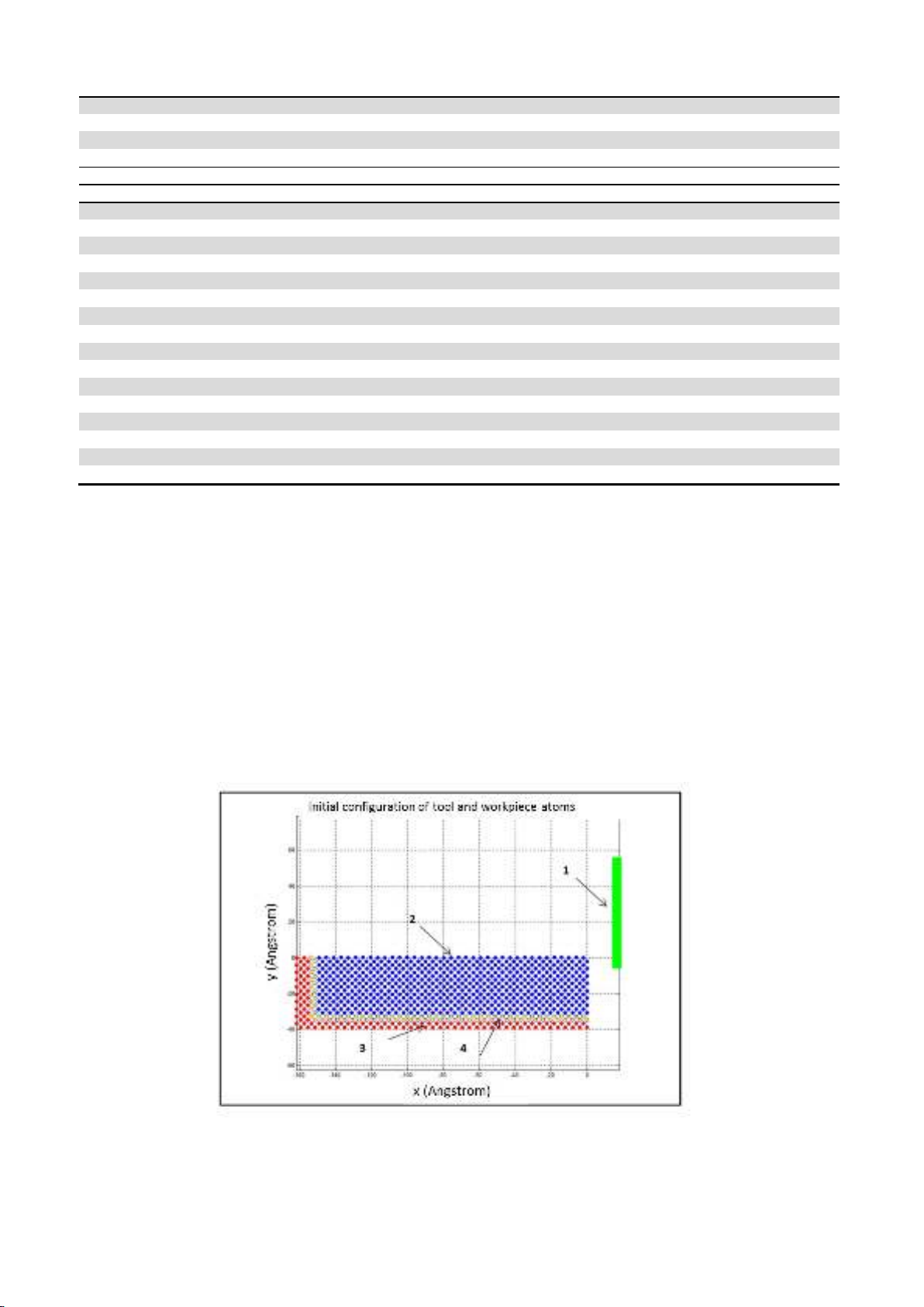
The main cutting tool and workpiece characteristics are depicted in Fig.1. The x-axis is considered
to be in the horizontal direction and the y-axis in the vertical direction. Thus, the cutting tool will move
towards the -x direction. The copper workpiece has dimensions of 143 Å x 35 Å and consists of 800
Cu atoms in an fcc lattice. The workpiece material consists of three distinct zones: the Newtonian, the
boundary and thermostat atoms. The main purpose of the use of the boundary atoms is to prevent the
Newtonian atoms from an unwanted displacement and subsequently preserve the shape of the
workpiece. These atoms are placed at the left edge and the bottom of the workpiece. The Newtonian
atoms are able to move according to the Newton’s equation of motion under the effect of inter-atomic
forces. Finally, two layers of thermostat atoms are also added to the model in order to regulate the
temperature in the workpiece. Thermostat atoms remain at a constant temperature, equal to the initial
bulk temperature of the workpiece, namely 293 K, and contribute to the heat dissipation. The
arrangement of all types of atoms is also depicted in Fig.1.
Fig.1. Geometric characteristics of the workpiece and the cutting tool and different types of atoms used
in the simulations (1: cutting tool; 2: workpiece; 3: boundary atoms; 4: thermostats)

A. P. Markopoulos et al. / Engineering Solid Mechanics 3 (2015)
199
The cutting tool has a rectangular shape, consists of 120 atoms and has dimensions of 60.06Å x
3.08Å. The cutting tool material is a single-crystal diamond. The tool is considered perfectly rigid and
a varying rake angle between 0 and 30o is used. In some cases, a tool with a different morphology,
consisting of 240 atoms, is used. The starting position of the tool is 2 Å right from the copper workpiece
in every case; cutting tool contains no boundary or thermostat atoms.
Both the Cu-Cu, within the workpiece atoms, and Cu-C, between cutting tool and workpiece atoms,
interactions are modeled using the Morse potential. The Morse potential parameters were selected from
the relevant literature (Girifalco and Weizer, 1959) and are presented in Table 2.
The Leapfrog numerical integration scheme is used for the time integration of the Newton
equations of motion. The time step value of 10fs was found to be sufficient for the time integration,
after conducting several test simulations with a time step range of 1-20 fs. The total cutting length is
130 Å and it is common for every case. For the regulation of the temperature, a velocity rescaling
algorithm, that enables the recalculation of velocities when a certain temperature difference is observed,
was employed.
Table 2. Morse potential function parameters
D (eV)
a (A-1)
re (A)
Cu-Cu
0.3429
1.3588
2.866
Cu-C
0.0870
5.1400
2.050
4. Results and Discussion
The mechanisms of chip formation as well as the effect of several parameters like depth of cut,
rake angle, cutting speed, tool size and shape, potential function and temperature regulation on the
nano-cutting process, were investigated throughout this paper. Two series of different model cases were
conducted, more specifically, cases including thermostat atoms and cases without thermostat atoms. In
the first series of the investigations, cases with three different depths of cut, namely 10, 15 and 20 Å,
four different rake angles, namely 0o, 10o, 20o and 30o, two different cutting speeds, 123 and 246 m/s,
two different cutting tool shapes and two different potential functions were evaluated. In the second
part of the investigations, the use of thermostat atoms for cases with four different cutting depths,
namely 8, 10, 12 and 14 Å and two different potential functions were conducted. Observations on the
effect of these parameters on chip formation mechanism, machined surface quality, cutting forces and
temperature distribution within the workpiece, were conducted.
4.1 Cases without thermostat atoms
4.1.1 Description of the chip formation mechanism
In Fig. 2 the results of the simulations with a cutting tool with 00 rake angle and 15 Å depth of cut,
for three different time steps are shown. At first, it was observed that the workpiece material is being
deformed in front of and around the area where the cutting tool moves, as it happens in conventional
cutting processes. The workpiece material far from these areas is barely affected by the movement of
the cutting tool. As the cutting process continues further, the chip moves along the tool surface. At the
end of the process, a chip is formed in front of the cutting tool. It was found that, with an increase of
the depth of cut, the deformation of the workpiece material increases and lower surface quality and
voids occur due to the more intense interactions between atoms. Furthermore, more anomalies are
observed in the chip shape and the irregularity of the machined surface increases.
4.1.2 Effect of tool rake angle and depth of cut
The increase in rake angle influences the chip formation, as the ratio of Fy/Fx decreases and an improved
surface quality is observed. Note that cutting forces ratio is indicative of friction between cutting tool and the
formed chip. In Fig. 3, the chip morphology is shown for three different rake angles, namely 10o, 20o


![Giáo trình Cấu trúc dữ liệu và giải thuật - Trường CĐ Cơ điện Hà Nội [Mới nhất]](https://cdn.tailieu.vn/images/document/thumbnail/2026/20260323/lionelmessi01/135x160/58171774381670.jpg)


![Giáo trình Tiện nâng cao (Nghề Cắt gọt kim loại, Trình độ Cao đẳng) - Trường Cao đẳng Cơ điện Hà Nội [Mới nhất]](https://cdn.tailieu.vn/images/document/thumbnail/2026/20260323/lionelmessi01/135x160/48101774403543.jpg)


