Faculty of Coastal Engineering Faculty of Coastal Engineering
BED, BANK & SHORE BED, BANK & SHORE PROTECTION PROTECTION
Lecturer: PhamThu Lecturer:
Huong PhamThu Huong
Chapter 4 Chapter 4 Erosion Flow -- Erosion Flow
(3 class hours)
Content Content
4.1 Introduction
4.2 Scour without protection
4.3 Scour with bed protection
4.6 Summary
Introduction Introduction
•• Scour
•• Erosion and Scour is the excess removal of Erosion and Scour is the excess removal of bed material by sediment transport. bed material by sediment transport. Scour -- the interaction between flow, the interaction between flow, structure and sediment structure and sediment •• Scour may be caused by: Scour may be caused by: (cid:137)(cid:137) change hydraulic conditions (e.g.
acceleration or change hydraulic conditions (e.g. acceleration or increased turbulence) increased turbulence) difference between sediment transport capacity (cid:137)(cid:137) difference between sediment transport capacity and sediment transport and sediment transport
The Scour process The Scour process
0
+
=
bz t
S x
∂ ∂
∂ ∂
In which: In which: -- ZZbb is the position of the bed is the position of the bed the total sediment transport per unit width --SSthe total sediment transport per unit width
General picture local erosion General picture local erosion
dynamic equilibrium situation dynamic equilibrium situation
(no sediment transport) clear water scour (no sediment transport) clear water scour
livelive--bed scour
bed scour (active bed
load transport) (active bed--load transport)
•• SS2 2 = S= S1 1 > 0 > 0 •• S2 > S1 = 0 S2 > S1 = 0 •• S2 > S1 > 0 S2 > S1 > 0
sediment transport is not always sediment transport is not always identical to sediment transport capacity identical to sediment transport capacity
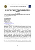
erosion due to turbulence Experiment –– erosion due to turbulence Experiment
Erosion downstream of a sill, due to turbulence Erosion downstream of a sill, due to turbulence
Influence average velocity; (cid:190)(cid:190) Influence average velocity; (cid:122)(cid:122) v = 0.2 m/s bed position and scouring hole at:
(cid:122)(cid:122) same for v = 0.3
0 min, 5 v = 0.2 m/s bed position and scouring hole at: 0 min, 5 min, 10 min, 20 min, 40 min, 80 min; min, 10 min, 20 min, 40 min, 80 min; 2 min, 5 min, 10 min, 20 min, same for v = 0.3 m/sm/s at:at: 2 min, 5 min, 10 min, 20 min, 40 min; 40 min;
Influence of Turbulence, by placing a sill on the (cid:190)(cid:190) Influence of Turbulence, by placing a sill on the rough bed, after 10, 20 and 40 min rough bed, after 10, 20 and 40 min
Sediment transport formula Sediment transport formula
S
f
) or
S
f
=
=
( ) ψ
( − ψ ψ c
threshold value
0
+
=
w c s
υ s
dynamic equilibrium
c z
∂ ∂
Settling sed. Stiring up sed.
scour during construction of scour during construction of Eastern Scheldt storm surge barrier Eastern Scheldt storm surge barrier
Structures suffering scour Structures suffering scour
, electrical cables flowlines, electrical cables
Barrages, tidal inlets, navigation channels with (cid:122)(cid:122) Barrages, tidal inlets, navigation channels with groynes groynes , seawalls, breakwaters groynes, seawalls, breakwaters (cid:122)(cid:122) groynes seabed pipelines, flowlines (cid:122)(cid:122) seabed pipelines, vertical pipes, piles, piers (cid:122)(cid:122) vertical pipes, piles, piers gravity based structures, platforms, offshore (cid:122)(cid:122) gravity based structures, platforms, offshore structures structures moorings and marinas (cid:122)(cid:122) moorings and marinas
Scour process Scour process
types of scour types of scour
scour without protection (cid:190)(cid:190) scour without protection jets and culverts (cid:122)(cid:122) jets and culverts detached bodies (bridge piers) (cid:122)(cid:122) detached bodies (bridge piers) attached bodies and constrictions (cid:122)(cid:122) attached bodies and constrictions abutments •• abutments groynes •• groynes
scour with bed protection (cid:190)(cid:190) scour with bed protection scour development in time (cid:122)(cid:122) scour development in time dustbin factor αα (cid:122)(cid:122) dustbin factor flow slides (cid:190)(cid:190) flow slides
Scour without protection Scour without protection
Scour in horizontal Jets and Culverts (cid:190)(cid:190) Scour in horizontal Jets and Culverts
Scour in horizontal Jets and Culverts (cid:190)(cid:190) Scour in horizontal Jets and Culverts
2
0
plane jet:
0.008
=
culvert
h se 2 B
c
u u *
⎛ ⎜ ⎝
⎞ ⎟ ⎠
0.33
0
0.65
=
0
circular jet :
0.08
=
h se D
c
u u *
⎛ ⎜ ⎝
⎞ ⎟ ⎠
h se D
u u *
c
Scour around detached body (cid:190)(cid:190) Scour around detached body
(from Breusers
Breusers / /
(cid:190)(cid:190) Scour around a cylinder
Scour around a cylinder (from , 1991) Raudkivi, 1991) Raudkivi
Scour around cylinder as function of Scour around cylinder as function of depth and diameter water--depth and diameter water
(Experiment results given by Breusers et al, 1977)
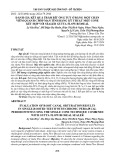
Bridge failure due to scour Bridge failure due to scour
Bridge which failed due to scour at the base of piers caused by a turbulent horseshoe vortex system
scour in case of other forms scour in case of other forms
Pier shape
l/b
KS
2
tanh
K K K
=
S
u
α
h s D
h 0 D
⎛ ⎜ ⎝
⎞ ⎟ ⎠
Ks = shape factor Kα= angle of attack Ku= velocity factor
1.0 1.2 1.1 1.0 0.85 0.8 0.6
- 1 3 5 2 3 5
Cylinder Rectangular Elliptic
Ku = 0 for u/uc < 0.5 Ku = 1 for u/uc > 1 and Ku = (2u/uc - 1) for 0.5 < u/uc < 1
Scour around abutments (cid:190)(cid:190) Scour around abutments
Abutment shape
Rectangular ("Blunt") Cylindrical Streamlined
KS (to be used in equation 1.0 0.75 - 1.0 0.5 – 0.75
Flow velocities and scour in Zeebrugge Flow velocities and scour in Zeebrugge
erosion in gradual constriction erosion in gradual constriction
1 −
1 m − m
=
=
u → =
Q B u h 1 1
1
B u h 2 2
2
2
u 1
→
= → =
B h 1 1 B h 2 2
1 −
m B 1 m B 2
m h 2 m h 1
h 2 h 1
B 1 B 2
⎛ ⎜ ⎝
⎞ ⎟ ⎠
=
=
m S B k u 1 1
B k u 2
m 2
⎫ ⎪ ⎬ ⎪ ⎭
(Assuming a relation between sediment transport and velocity: S =kum, in which m = 4 ÷ 5)
groyne Scour around groyne Scour around
2 / 3
2.2
+
=
h 0
h se
Q ⎛ ⎜ B b −⎝
⎞ ⎟ ⎠
Scour with bed protection Scour with bed protection
Scouring formula for clear-water scour behind a bed protection:
u u
h
( α −
)1.7
0.2 0
0.4
t
=
( ) h t s
0.7
10
c Δ
original water depth vertically averaged velocity at end of protection critical velocity time in hours dust bin parameter
hs(t) maximum scour depth h0 u uc t α
influence of αα influence of
use local value of α αL = 1.5 + 5 r (for αL >1.8)
comparison model and prototype comparison model and prototype
De Grauw and Pilarczyk 1981
values of αα for vertical and horizontal for vertical and horizontal values of =10) constrictions (for L/h00=10) constrictions (for L/h
relation between αα, turbulence and length , turbulence and length relation between
f
f
C
with
(
1 for
40)
α=
1.5 5 +
=
=
≤
r f 0
c
c
c
C 40
From Hoffmans (1993)
The r0 comes from Hoffmans and Hinze
steps to calculate αα steps to calculate
Hinze (1975):
g
1.08
2 −
−
0.0225(1
)
(
1)
=
−
+
+
r 0
D h
L D 6 − 6.67 h
5 1.4 C
eq. 2.13 D = step height h = downstream waterdepth
Hoffmans (1992, 1993)
αL = 1.5 + 5 r
Hoffmans and Booij (1993)
f
f
C
with
(
1 for
40)
α=
1.5 5 +
=
=
≤
r f 0
c
c
c
C 40
Trinh (1993)
)
f
α=
(1.5 5 +
r f 0
c
u
Bs is original gap width b is reduced gap width
2.2
f
1 3.6 (1
)
= +
−
u
b B s
equilibrium clear water scour equilibrium clear water scour
0.5
u
α
0.5
c
s =
+
u u α − u
u )
u h 0
= c ( u h 0 s
h se
h se → = h 0
c
⎫ ⎪ ⎬ ⎪⎭
live bed scour live bed scour
cot
cot
I
=
+
(
)
β 1
β 2
2 h s
3.4
1.4
0.8
0.8
−
t
K t
cot
=
+
Δ
u u −
=
( α
)
( .005 cot
)
β 1
β 2
0.4 h 0
c
1 2 ⎡ ⎣
⎤ ⎦
0.8
I
K t
S t
=
− ⋅ →
=
red
red
h s
cot
+
( 0.5 cot ⋅
)
β 2
I red β 1
5
0.2
−
0.8 e
e
→
→
→
e
(
)
K t S t − ⋅ K K t S t 0 0.8 = = = = h se dI dt 0.8 S ⎛ ⎜ ⎝ ⎞ ⎟ ⎠ cot cot + β 1 β 2 1 2
stability of protection stability of protection
β
This distance has to be large enough L = f(β)
the slope angle ββ the slope angle
4 −
f
=
⋅
+
0.11 0.75 +
β
(
)
r 0
c
2 u 0 gd
Δ
50
⎡ arcsin 3 10 ⎢ ⎣
⎤ ⎥ ⎦
(
,
1 for
40)
f
f
C
=
=
≤
c
c
C 40
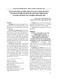
stability and slides stability and slides
- Sliding occurs after a slope has lost its stability. The final slope will be gentler than the angle of repose φ. 1:6 can serve as an indication of an average slope for density packed sand. - When a shear stress is exerted on loose sand, the grains tend to a denser packing, producing an excess pressure on the pore water and thus forcing it out of the pores. This excess pore pressure in loosely packed sand decreases the contact forces between the grains (cid:198) reduction of the shear strength. -- (cid:198) The soil becomes, temporarily, a thick fluid ⇒ liquefaction.
slide schematic view of a flow--slide schematic view of a flow
Summary Summary