UFC 3-460-03
21 JANUARY 2003
59
Figure 6.5. ESO Valve (136AF-9B).
6.4.6.2. Valve Setting. Turn the adjusting stem of the CDB-7 clockwise to increase the DP and
counterclockwise to decrease it. The DP should be about 10 psi.
6.4.7. Issue Venturi. The 254-millimeter (10-inch) issue venturi is downstream of the ESO valve and
is typically rated at 9085 liters per minute (2400 gallons per minute). It is similar to an orifice plate
in operation but is much more accurate. It has four 12.7-millimeter connections for piping in the
DPTs. Using signals from the DPTs, the microprocessor measures issue flow with the return-flow
venturi, and controls starting and stopping of the sequential pumps.
6.4.8. Pressure Indication Transmitter (PIT). Two PITs are connected directly to the main issue line
just downstream of the ESO valve. The PITs read system pressure between 0 and 250 psi. The
microprocessor is programmed to call on the lead pump when system pressure drops below 60 psi
and call it off when system pressure reaches a preset pressure between 135 and 175 psi. The
microprocessor uses the 4- to 20-milliampere signals from these two transmitters to turn the lead
pump on or off. This signal is directly proportional to the pressure being measured. Calibrate the
PIT with a manometer; the digital type is recommended. Refer to the manufacturer’s instructions for
details.
6.4.9. DPT. DPTs measure DP across the venturi and have displays that express flow in gallons per
minute. There are two DPTs connected to the issue venturi (the range is 0 to 9085 liters per minute
[0 to 2400 gallons per minute]) and four connected to the return venturi. Two of the four are for low
flows with a range of 0 to 379 liters per minute (0 to 100 gallons per minute) and the remaining two
are for high flows with a range of 0 to 3028 liters per minute (0 to 800 gallons per minute). The
microprocessor uses the 4- to 20-milliampere signals from these six transmitters to turn sequential
pumps on or off. This signal is directly proportional to the DP being measured. Calibrate the DPTs
with a manometer; the digital type is recommended. Refer to the manufacturer’s instructions for
details.
6.4.10. Hydrant Loop. After leaving the issue venturi, fuel flows through the hydrant loop back to
the operating storage tank. The loop is under the parking apron with a hydrant control pit at each
Simpo PDF Merge and Split Unregistered Version - http://www.simpopdf.com
UFC 3-460-03
21 JANUARY 2003
60
fueling point. In the automatic idle mode the loop is under constant pressure (75 psi) and protected
from thermal expansion by relieving excess pressure to the operating storage tank. A drop in system
pressure to 60 psi causes the lead pump to be energized. Because the hydrant loop is very long, high-
point vents and low-point drains are provided throughout. The number and location of hydrant
outlets are based on the types of aircraft and mission fueling requirements. The hydrant pit is molded
fiberglass with a counterbalanced aluminum cover. It opens to 90 degrees and requires
133.4 newtons (30 pounds force) to open it and 222 newtons (50 pounds force) to close. Most new
covers are designed to be watertight. Pipe penetrations in the pit are sealed by Buna-N boots clamped
to the pipe. The hydrant riser is either 101 millimeters for 2271-liter-per-minute (600-gallon-per-
minute) flows or 152 millimeters for 4542.4-liter-per-minute (1200-gallon-per-minute) flows. An
appropriately sized ball valve is installed before the HCV.
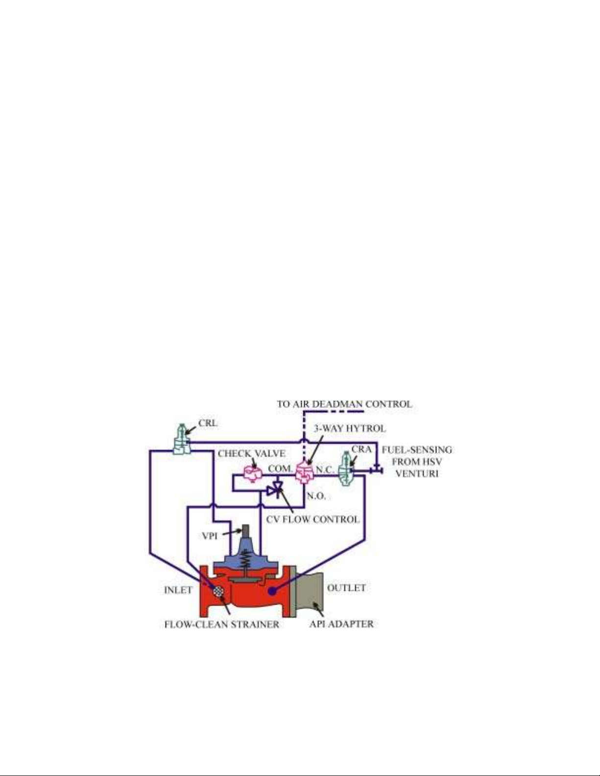
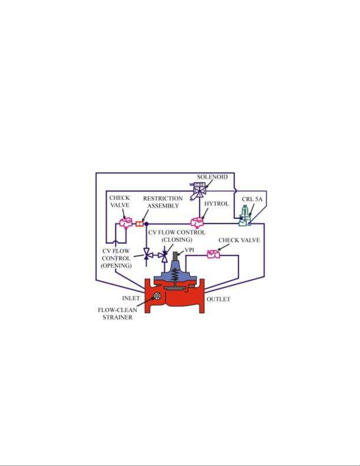
6.4.11. HCV (362AF-8):
6.4.11.1. The HCV (Figure 6.6) provides a constant nozzle pressure and relieves excess pressure.
An air-sensing line is connected from the HSV to the HCV three-way hytrol. When the HSV's
pneumatic deadman is depressed, air is supplied to the three-way hytrol, allowing the valve to
open. A fuel-sensing line is connected from the HSV venturi to the pressure-reducing control
(CRA) and the CRL on the 362AF-8. The venturi is calibrated to provide the same pressure as the
actual nozzle pressure at the skin of the aircraft. The CRA maintains 45 psi at the nozzle. The
HCV is designed to close rapidly when the nozzle pressure exceeds the 50-psi setting of the CRL.
It reopens when the pressure drops below this set point.
Figure 6.6. HCV (362AF-8).
6.4.11.2. Valve Setting. Typical settings for the CRA is 45 psi and CRL is 50 psi. Set these
controls by turning the adjusting stem clockwise to increase pressure and counterclockwise to
decrease pressure. After establishing fuel flow through the HSV to a refueling truck, bottom the
CRL on the 362AF-8. Adjust the CRA to 50 psi and turn the CRL adjusting stem
counterclockwise until the valve begins to close. Next, turn the CRA counterclockwise until the
nozzle pressure drops to 45 psi. The main valve opening speed is adjusted by turning the CV flow-
Simpo PDF Merge and Split Unregistered Version - http://www.simpopdf.com
UFC 3-460-03
21 JANUARY 2003
61
control adjusting stem clockwise to make the valve open slower and counterclockwise to make the
valve open faster. Most valves are set for about 20 seconds; however, to dampen the nozzle
pressure wave, the opening speed may need to be retarded. NOTE: An HCV is also located at the
HSV check-out stand.
6.4.12. HSV. The Brooks valve on the HSV serves as a secondary CRL if the nozzle pressure
reaches 55 psi. The air pressure setting on the HSV dictates the set point of the Brooks valve. The
air pressure must be set 10 psi above the pressure relief setting required by the Brooks valve. Setting
the air pressure at 65 psi will close the Brooks valve at 55 psi. The HCV will close within five
seconds if a pneumatic hose ruptures and bleeds air from the system. For newer HSVs, the pressure-
setting procedures may be different; refer to the manufacturer’s instructions. The HCV is equipped
with an API adapter (364AF-2).
6.4.13. Return Venturi. The 101-millimeter return venturi is upstream of the back-pressure control
valve (BPCV). It is similar to the issue venturi but is rated at 3028 liters per minute
(800 gallons per minute).
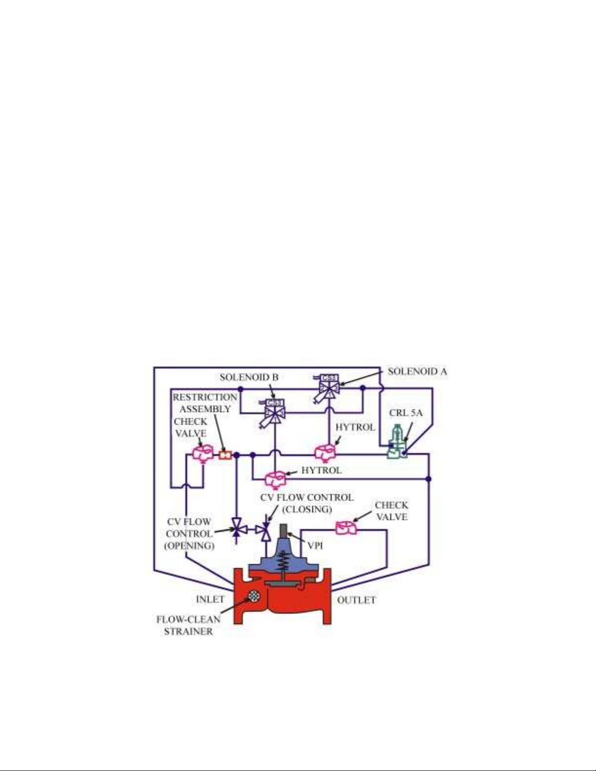
6.4.14. BPCV (58AF-9):
6.4.14.1. The BPCV (Figure 6.7) set point is 100 psi, measured at the inlet of the furthest hydrant
outlet. It modulates to maintain loop pressure at the set point. The valve also prevents reverse
flow. This 152-millimeter valve has a solenoid that is energized when the lead pump is called on
and is de-energized when the system starts the shut-down sequence. When the solenoid is
energized the valve is enabled, meaning the valve opens and closes as the CRL dictates. When it
is de-energized the valve closes.
Figure 6.7. BPCV (58AF-9).
6.4.14.2. Valve Setting. Place a person at the furthest hydrant outlet with a means of
communicating with the person at the BPCV. To establish 100 psi at the furthest hydrant outlet,
Simpo PDF Merge and Split Unregistered Version - http://www.simpopdf.com
UFC 3-460-03
21 JANUARY 2003
62
turn the BPCV CRD adjusting stem clockwise to increase pressure and counterclockwise to
decrease pressure.
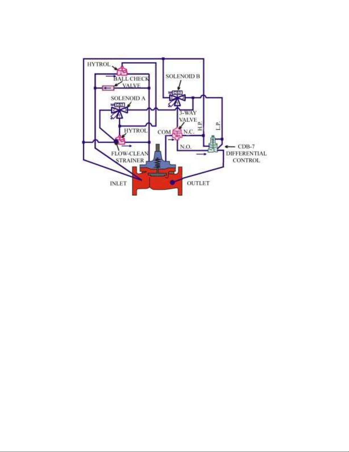
6.4.15. Defuel/Flush Valve (D/FV) (58AF-9-1):
6.4.15.1. This valve (Figure 6.8) is controlled by two different solenoids: solenoid A controls the
defuel portion of the main valve and holds the valve closed any time a fueling pump is running;
solenoid B controls the flush portion of the main valve and functions only when the system is
placed in the flush mode. When the lead pump de-energizes, solenoid A energizes, allowing the
valve to open and drop the system pressure to 80 psi. While the system is in the idle position, the
valve will open to allow defueling when the hydrant loop pressure rises above 80 psi. Defueling is
conducted by using the HSV to pump the fuel off the plane and force the fuel into the hydrant loop
at a rate of 1135 liters per minute (300 gallons per minute) and 165 psi. 165 psi will overcome the
80-psi setting of the 58AF-9-1 D/FV and the valve opens. Solenoid B energizes only when the
system is placed in the flush mode. The reason for system flushing is to move fuel through the
pipeline as fast as possible and clean the loop. With the system in the flush mode, energize all
available fueling pumps by placing the pumps’ Hand-Off Auto switch in the “Hand” position to get
the maximum meter-per-second (foot-per-second) flow in the hydrant loop. The 58AF-9-1 D/FV
valve opens, allowing the maximum amount of fuel to flow through the system.
Figure 6.8. D/FV (58AF-9-1).
6.4.15.2. Valve Setting. Close the manual valve upstream of the 58AF-3, Pressure Control Valve
(PCV) to ensure system pressure does not flow through the valve while adjusting the D/FV.
Bottom the CRL on the D/FV. Place the system in automatic mode and pressurize the system.
When the system shuts down, turn the CRL adjusting stem on the D/FV counterclockwise until the
Simpo PDF Merge and Split Unregistered Version - http://www.simpopdf.com
UFC 3-460-03
21 JANUARY 2003
63
gauge reads 80 psi. Repressurize the system to check the setting. When complete, reopen the
manual valve upstream of the PCV.
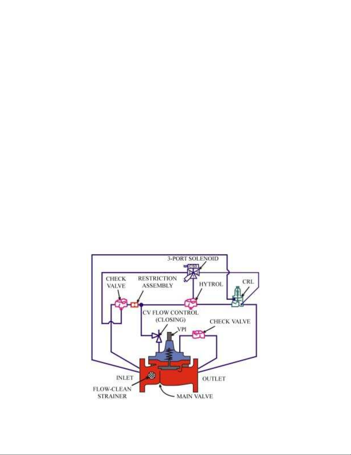
6.4.16. PCV (58AF-3).
6.4.16.1. This 50.8-millimeter valve (Figure 6.9) reduces system pressure down to
75 psi during the system shutdown process and provides thermal relief during idle periods. The
valve has a solenoid that is energized to close the valve when a pump is running and de-energizes
when the lead pump de-energizes. When de-energized, the valve opens to reduce the system
pressure to 75 psi and the thermal relief function is operable. If the pressure rises above
75 psi, the valve opens and the excess pressure flows to the immediate operating storage tank. The
valve opening and closing speed controls are typically set at three seconds. In some cases, to
prevent valve chattering, the PCV pressure-sensing line is connected to the large defuel/flush line.
Figure 6.9. PCV (58AF-3).
6.4.16.2. Pressure Setting. Bottom the PCV 58AF-3 CRL. Place the system in the automatic mode
and pressurize the system. When the system shuts down, turn the CRL adjusting stem on the PCV
counterclockwise until the gauge reads 75 psi. Repressurize the system to check the setting.
6.4.17. HSV Check-Out Stand. The check-out stand consists of a 362AF-8 HCV with a 364AF-2
API adapter, four 63.5-millimeter (2.5-inch) single-point receptacles (SPR), and an emergency stop
switch. The HCV is piped into the hydrant loop just downstream of the issue venturi. The HSV
check-out stand is used to perform daily checks of the HSV before using it to service aircraft.
6.5. Product Recovery System.
6.5.1. Tank Design. The product recovery tank is a 15,141-liter (4000-gallon) double-walled steel
tank with an interstitial leak monitor. The annular space provided between the primary and secondary
Simpo PDF Merge and Split Unregistered Version - http://www.simpopdf.com


![Giáo trình Kỹ thuật chung về ô tô (Nghề: Công nghệ ô tô) - Trường Cao đẳng Bách Khoa Tây Nguyên [Mới Nhất]](https://cdn.tailieu.vn/images/document/thumbnail/2025/20251212/laphong0906/135x160/39771779074470.jpg)
![Giáo trình Kỹ thuật chung về ô tô và công nghệ sửa chữa (Nghề: Công nghệ ô tô) - Trường Cao đẳng Bách Khoa Tây Nguyên [Mới Nhất]](https://cdn.tailieu.vn/images/document/thumbnail/2025/20251212/laphong0906/135x160/23311779074471.jpg)


![Giáo trình Hệ thống nhiên liệu động cơ ô tô (CĐ) - Trường Cao đẳng Công nghiệp Thanh Hóa [Ngành Công nghệ ô tô]](https://cdn.tailieu.vn/images/document/thumbnail/2026/20260511/hoatrami2026/135x160/37511778728704.jpg)
![Giáo trình Hệ thống phanh ABS Công nghệ ô tô (CĐ) - Trường Cao đẳng Công nghiệp Thanh Hóa [Mới nhất]](https://cdn.tailieu.vn/images/document/thumbnail/2026/20260511/hoatrami2026/135x160/1901778728704.jpg)


![Giáo trình Hệ thống điện thân xe ô tô (CĐ) - Trường Cao đẳng Công nghiệp Thanh Hóa [Mới nhất]](https://cdn.tailieu.vn/images/document/thumbnail/2026/20260511/hoatrami2026/135x160/611778728708.jpg)


%20--%3e%3cdefs%3e%3cstyle%3e%20.st0%20{%20fill:%20%23fff;%20}%20.st1%20{%20fill:%20%237800fa;%20}%20%3c/style%3e%3c/defs%3e%3cpath%20class='st1'%20d='M117.78,12.18H43.11c2.9,3.47,4.65,7.94,4.65,12.82,0,5.6-2.3,10.66-6.01,14.29h76.02l7.22-13.56-7.22-13.56Z'/%3e%3cg%3e%3cpath%20class='st0'%20d='M53.58,26.17h-.59v-1.46h.59v-4.96h2.83c1.78,0,2.67.94,2.67,2.82v5.76c0,1.87-.89,2.81-2.67,2.81h-2.83v-4.96ZM55.36,21.37v3.34h1.1v1.46h-1.1v3.34h1.01c.61,0,.91-.37.91-1.1v-5.93c0-.74-.3-1.1-.91-1.1h-1.01Z'/%3e%3cpath%20class='st0'%20d='M65.99,31.14h-1.8l-.31-2.07h-2.19l-.31,2.07h-1.64l1.82-11.39h2.62l1.82,11.39ZM65.28,18.04c-.25.46-.51.77-.75.94-.21.15-.47.22-.79.22-.26,0-.57-.07-.92-.22l-.38-.15c-.14-.05-.26-.07-.37-.07-.3,0-.53.18-.71.54l-.91-.68c.25-.46.51-.77.75-.94.21-.14.48-.21.79-.21.26,0,.57.07.92.21l.38.15c.14.05.26.07.37.07.3,0,.53-.18.71-.54l.91.68ZM61.91,27.52h1.73l-.87-5.76-.87,5.76Z'/%3e%3cpath%20class='st0'%20d='M74.53,26.89v1.52c0,1.91-.89,2.86-2.67,2.86s-2.67-.95-2.67-2.86v-5.93c0-1.91.89-2.86,2.67-2.86s2.67.95,2.67,2.86v1.11h-1.69v-1.22c0-.75-.31-1.12-.93-1.12s-.93.37-.93,1.12v6.15c0,.74.31,1.11.93,1.11s.93-.37.93-1.11v-1.63h1.69Z'/%3e%3cpath%20class='st0'%20d='M81.4,31.14h-1.8l-.31-2.07h-2.19l-.31,2.07h-1.64l1.82-11.39h2.62l1.82,11.39ZM75.9,19.2l1.52-1.91h1.71l1.51,1.91h-1.61l-.76-.95-.75.95h-1.61ZM77.32,27.52h1.73l-.87-5.76-.87,5.76ZM83.1,15.99l-1.76,1.91h-1.26l1.17-1.91h1.86Z'/%3e%3cpath%20class='st0'%20d='M84.86,19.75c1.78,0,2.67.94,2.67,2.82v1.48c0,1.87-.89,2.81-2.67,2.81h-.85v4.28h-1.79v-11.39h2.64ZM84.01,21.37v3.86h.85c.58,0,.87-.36.87-1.08v-1.71c0-.71-.29-1.07-.87-1.07h-.85Z'/%3e%3cpath%20class='st0'%20d='M93.51,19.75c1.78,0,2.67.94,2.67,2.82v1.48c0,1.87-.89,2.81-2.67,2.81h-.85v4.28h-1.79v-11.39h2.64ZM92.66,21.37v3.86h.85c.58,0,.87-.36.87-1.08v-1.71c0-.71-.29-1.07-.87-1.07h-.85Z'/%3e%3cpath%20class='st0'%20d='M98.8,31.14h-1.79v-11.39h1.79v4.88h2.03v-4.88h1.83v11.39h-1.83v-4.88h-2.03v4.88Z'/%3e%3cpath%20class='st0'%20d='M105.36,24.55h2.46v1.62h-2.46v3.34h3.09v1.63h-4.88v-11.39h4.88v1.63h-3.09v3.18ZM108.17,17.29l-1.76,1.91h-1.26l1.17-1.91h1.86Z'/%3e%3cpath%20class='st0'%20d='M112.2,19.75c1.78,0,2.67.94,2.67,2.82v1.48c0,1.87-.89,2.81-2.67,2.81h-.85v4.28h-1.79v-11.39h2.64ZM111.35,21.37v3.86h.85c.58,0,.87-.36.87-1.08v-1.71c0-.71-.29-1.07-.87-1.07h-.85Z'/%3e%3c/g%3e%3ccircle%20class='st1'%20cx='25'%20cy='25'%20r='20'/%3e%3cpath%20class='st0'%20d='M32.78,19.27c2.92,0,4.43,2.55,5.28,5.33l.71,2.17c.14.38-.33.75-.71.75h-5.61c.19-.33.24-.71.09-1.08l-.75-2.45c-.43-1.32-.99-2.64-1.79-3.77.75-.57,1.65-.94,2.78-.94h0ZM25,18.38c3.25,0,4.9,2.78,5.89,5.89l.76,2.45c.14.42-.33.8-.8.8h-11.69c-.42,0-.94-.38-.8-.8l.75-2.45c.99-3.11,2.64-5.89,5.89-5.89h0ZM25,11.35c1.74,0,3.11,1.37,3.11,3.11s-1.37,3.11-3.11,3.11-3.11-1.41-3.11-3.11,1.41-3.11,3.11-3.11h0ZM17.27,19.27c1.08,0,1.98.38,2.73.94-.8,1.13-1.37,2.45-1.74,3.77l-.8,2.45c-.14.38-.05.75.09,1.08h-5.56c-.42,0-.9-.38-.75-.75l.71-2.17c.9-2.78,2.41-5.33,5.33-5.33h0ZM17.27,12.91c1.51,0,2.78,1.27,2.78,2.83s-1.27,2.83-2.78,2.83-2.83-1.27-2.83-2.83,1.27-2.83,2.83-2.83h0ZM32.78,12.91c1.56,0,2.78,1.27,2.78,2.83s-1.23,2.83-2.78,2.83-2.83-1.27-2.83-2.83,1.27-2.83,2.83-2.83h0ZM27.07,28.56v.09c0,.57-.24,1.08-.61,1.46h0v.05c-.38.33-.9.57-1.46.57s-1.08-.24-1.46-.61h0c-.38-.38-.61-.9-.61-1.46v-.09h1.41v.09c0,.19.05.38.19.47v.05c.09.09.28.19.47.19s.38-.09.47-.19v-.05c.14-.09.24-.28.24-.47t-.05-.09h1.41ZM30.99,28.56v.09c0,1.65-.66,3.16-1.74,4.24-1.08,1.08-2.59,1.79-4.24,1.79s-3.16-.71-4.24-1.79l-.05-.05c-1.04-1.08-1.7-2.55-1.7-4.2v-.09h1.41v.09c0,1.27.47,2.4,1.27,3.25h.05c.85.85,1.98,1.37,3.25,1.37s2.4-.52,3.25-1.37c.85-.8,1.37-1.98,1.37-3.25v-.09h1.37ZM34.99,28.56v.09c0,2.78-1.13,5.28-2.92,7.07-1.79,1.79-4.29,2.92-7.07,2.92s-5.23-1.13-7.07-2.92c-1.79-1.79-2.92-4.29-2.92-7.07v-.09h1.41v.09c0,2.4.94,4.53,2.5,6.08,1.56,1.56,3.72,2.5,6.08,2.5s4.52-.94,6.08-2.5c1.56-1.56,2.5-3.68,2.5-6.08v-.09h1.41Z'/%3e%3c/svg%3e)