Journal of Water Resources & Environmental Engineering - No. 87 (12/2023)
2
Mechanical behavior of functionally-Graded concrete beam
under flexural loading
Nguyen Viet Duc
1
Abstract: This paper presents the mechanical behavior of functionally-
graded concrete (FGC) beam
under flexural bending. The FGC beam was made of conventional concrete of strength class 30MPa
with a thickness of 45mm and high performance glass fiber reinforced concrete (HPGFRC) of st
rength
class 60MPa with thickness of 15mm. While the reference beam is composed of entirely conventional
concrete of strength class 30MPa with thickness of 60mm. Both of the beams were reinforced by using
two steel bars at the bottom with a concrete cover of 25 mm. Based on the third-
point bending test,
both the reference and FGC beam behaved in a similar manner, even though the latter consists of two
layers of conventional concrete and HPGFRC. Their mechanical behavior is represented in four stages
including the first crack propagation, the second crack appearance, reinforcement load-
carrying
capacity, and finally failure. Cracking and ultimate strength obtained from the FGC beam were 19% and
28% higher than those from the reference beam. The better per
formance of the FGC beam was mainly
due to the functionality of HPGFRC with higher strength and glass fiber inclusion. By observing the
failure of the FGC beam, there is no crack or delamination between the conventional concrete and
HPGFRC layers on this beam.
Keywords: Functionally-
graded concrete, flexural loading, glass fiber, high performance glass fiber
reinforced concrete.
1. Introduction
*
The application of functionally graded
material in concrete has attracted more and
more attention over the last years. Ma et al. (Ma
et al., 2009) proposed a functionally graded
concrete segment in shield tunnel. The segments
used in shield tunneling lining structures should
have high durability and long service life. Based
on the principle of functionally graded materials
(FGMs), the FGMs for reinforced concrete
segments were designed and optimized. By the
method of multi-layer vibrating formation, the
segments with characteristics such as high
impermeability of the covering layer, high
strength of the main structural layer, and fire-
resistance of an inner layer, were prepared.
1
Division of Construction Materials, Faculty of Civil
Engineering, Thuyloi University
Received 13
th
Jul. 2023
Accepted 10
th
Aug. 2023
Available online 31
st
Dec. 2023
Furthermore, a good manufacturing technique
for the interface was adopted to ensure the
homogeneous transition of different material
layers, and the integrated design effects of
function and structure were achieved.
On the other hand, Maalej et al. (Maalej et
al., 2003) reported the results of an experimental
program on the effectiveness of a ductile fiber
reinforced cementitious composite (DFRCC)
material, which exhibit strain-hardening and
multiple-cracking behavior under flexural
loadings, in retarding the corrosion of steel in
reinforced concrete (RC) beams. Based on the
collective findings from theoretically-estimated
steel losses, rapid chloride permeability tests,
pH value tests, as well as structural tests, it was
concluded that functionally-graded concrete
(FGC) beams, where a layer of DFRCC material
was used around the main longitudinal
reinforcement, had noticeably higher resistance

Journal of Water Resources & Environmental Engineering - No. 87 (12/2023)
3
against reinforcement corrosion compared to a
conventional RC beam. Besides, Maalej &
Leong (Maalej & Leong, 2005) investigated the
corrosion resistance and failure characteristic of
functionally graded concrete beam and ordinary
concrete beam. The experiment reveals that,
compared to ordinary concrete beams,
functionally graded reinforced concrete beams
have better resistance to corrosion, and thus
more durable. B
In this study, the author intends to present the
mechanical behavior of functionally-graded
concrete (FGC) beam under flexural loading. The
FGC beam consists of the layer of conventional
concrete of strength class 30MPa with a thickness
of 45mm and the layer of high performance glass
fiber reinforced concrete (HPGFRC) of strength
class 60MPa with a thickness of 15mm. The FGC
beam is studied in comparison with the reference
beam, which consists of the entire layer of
conventional concrete of strength class 30MPa
with a thickness of 60mm.
2. Specimen preparation and experimental
program
2.1. Material used
This study used ordinary Portland cement
PC40, conforming to the European cement
standard EN 197-1. Silica fume was used as a
supplementary cementitious material. Fine and
coarse aggregates for concrete production are
manufactured sand and crushed stone
respectively. Alkali resistant glass fibers,
conforming to ASTM C1666, were used for the
HPGFRC mix. Besides, a third generation
polycarboxylate superplasticizer was involved.
Lastly, tap water at Hanoi area was used for the
proportion mix. Details of the material used in this
study in term of physical and mechanical
characteristics of cement and silica fume, sieve
analysis and characteristics of coarse and fine
aggregates, as well as characteristic of glass fibre
fiber, superplasticizer, and water can be found in
the previous publications (Nguyen, 2020).
2.2. Mix proportion of conventional
concrete and HPGFRC
In this study, two types of concrete mix
proportions were designed. The first one was
conventional concrete of strength class 30 MPa.
This type of concrete was used for the
preparation of the reference beam. While the
second is HPGFRC mix of strength class 60
MPa that is used in combination of the
abovementioned conventional concrete to form
FGC beam. Taking into account that HPGFRC
is also a high strength self-compacting mortar.
Some “trial-and-error” were involved to adjust
the dosage of water and superplasticizer content.
Eventually, the mix proportion and properties of
conventional concrete and HPGFRC used in this
study were obtained and they can be found in
details in Refs (Ngo, 2020; Nguyen, 2020).
2.3. Specimen preparation
Both the reference beam and FGC beam
have a similar size of 400mm length, 100mm
width, and 60mm height. There are two steel
bars of diameter 6mm playing a role as
reinforcement to avoid an abrupt failure of the
beam. The concrete cover is 25mm. The
reference beam was cast by placement of
conventional concrete and a subsequent
adequate vibration for the entire layer of 60mm.
While the FGC beam was cast in two steps;
firstly, conventional concrete was placed and
vibrated properly, then HPGFRC was poured
above the conventional concrete at the fresh
state in the same mold to form the FGC beam.
Since HPGFRC is a self-compacting mix, it
does not need vibration to compact. The only
difference between the reference and FGC
beams is the latter consists of conventional
concrete and HPGFRC, in which the beam
height thickness of the HPGFRC layer is 15mm
and the rest of conventional concrete is 45mm.
After casting, the beams were cured at the
standard conditions and then used for the
experimental tests at 28 days. The detailed
Journal of Water Resources & Environmental Engineering - No. 87 (12/2023)
4
process of the specimen preparation is presented
elsewhere in References (Nguyen, 2020).
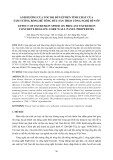
2.4. Experimental program
The reference and FGC beams were subjected
to third-point loading. The bending test was used
with a span length of 300 mm and the distance
between load application points is 100 mm.
Besides, an extensometer was mounted in the
middle of the beam to capture the displacement
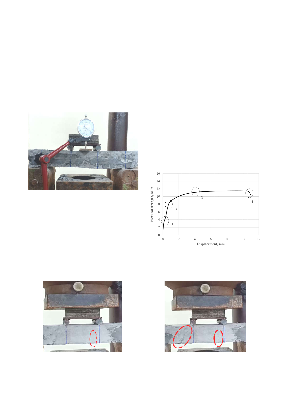
during the test, as can be seen in Figure 1.
Figure 1. Experimental test set-up
During the bending test, there is a sagging and
hogging moment exerting on the beam, where the
bottom layer is under tension and the top layer is
under compression. Since HPGFRC owns high
tensile strength thanks to fiber inclusion, during
the test the FGC beam was placed so that the
HPGFRC layer is at the bottom in order to take
advantage of HPGFRC functionality.
The test was performed using a hydraulic
testing machine, and the load rate was 1kN per
minute. The test was conducted up to beam
failure to acquire its maximum loading capacity.
3. Results and discussion
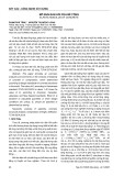
3.1. Reference beam behavior
The flexural strength versus displacement
relationship of the reference beam is shown in
Figure 2. It can be seen that there are four
principal stages during the flexural test on the
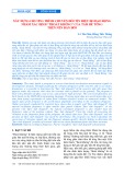
reference beam. The first one (point 1 in Figure
2) is the moment when the first visible crack
appeared at about 3MPa. The illustration of the
first crack appearance can be observed in Figure
3. The crack is propagated in the middle third of
the beam, where it commonly receives the
maximum bending moment.
Figure 2. Flexural strength versus displacement
relationship of the reference beam
Figure 3. Crack propagation at the first stage
(point 1 in Figure 2)
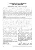
Figure 4. Crack propagation at the second stage
(point 2 in Figure 2)
Journal of Water Resources & Environmental Engineering - No. 87 (12/2023)
5
After that, the beam is still able to carry more
loads, and the second crack appears on the left
third of the beam at about 8MPa (point 2 in
Figure 2), as noted in Figure 4. In the meantime,
the first crack still develops wider and wider. At
this moment, steel bar reinforcement is the main
component to carry the load (point 3 in Figure
2) and the second crack develops much more
than the first one, as can be seen in Figure 5.
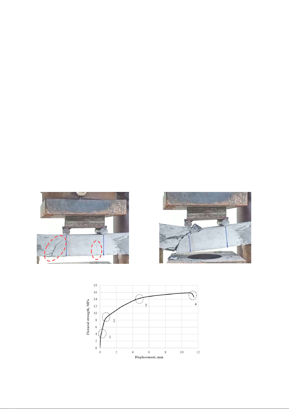
The beam is considered to be failed when there
is a big displacement, which excelscapacity of the
extensormeter and the testing machine (point 4 in
Figure 2), and the beam no longer carries more
load. It is noted that from the second crack
appearance up to the failure, the increment of
load-carrying capacity is much lower than the
increment of displacement. As shown in Figure 6,
the beam fails at the second crack on the left third
of the beam, where it receives maximum shear
loading during the test.
3.2. FGC beam behavior
Similar to the case of the abovementioned
reference beam, there are also four principal
stages during the flexural test on the FGC beam,
as can be observed in Figure 7 representing the
relationship of flexural strength versus
displacement. The first crack (point 1 in Figure
7) appears in the middle third at about 3.6MPa,
as can be seen in Figure 8. The second crack
appears on the right third, as shown in Figure 9,
at about 9MPa (point 2 in Figure 7).
After that, the FGC beam carries more load
(point 3 in Figure 7), but at this moment the load is
transferred mostly to the steel bar reinforcement.
The first crack seems to be opened wider than the
second one, as shown in Figure 10, and the beam
continues to be bent. Up to the moment, the beam
does not carry more loads, it is considered to be
failed (point 4 in Figure 7). The beam fails at the
first crack, as can be seen in Figure 11.
Figure 5. Crack propagation at the third stage
(point 3 in Figure 2)
Figure 6. Failure development at the final stage
(point 4 in Figure 2)
Figure 7. Flexural strength versus displacement relationship of the FGC beam
Journal of Water Resources & Environmental Engineering - No. 87 (12/2023)
6
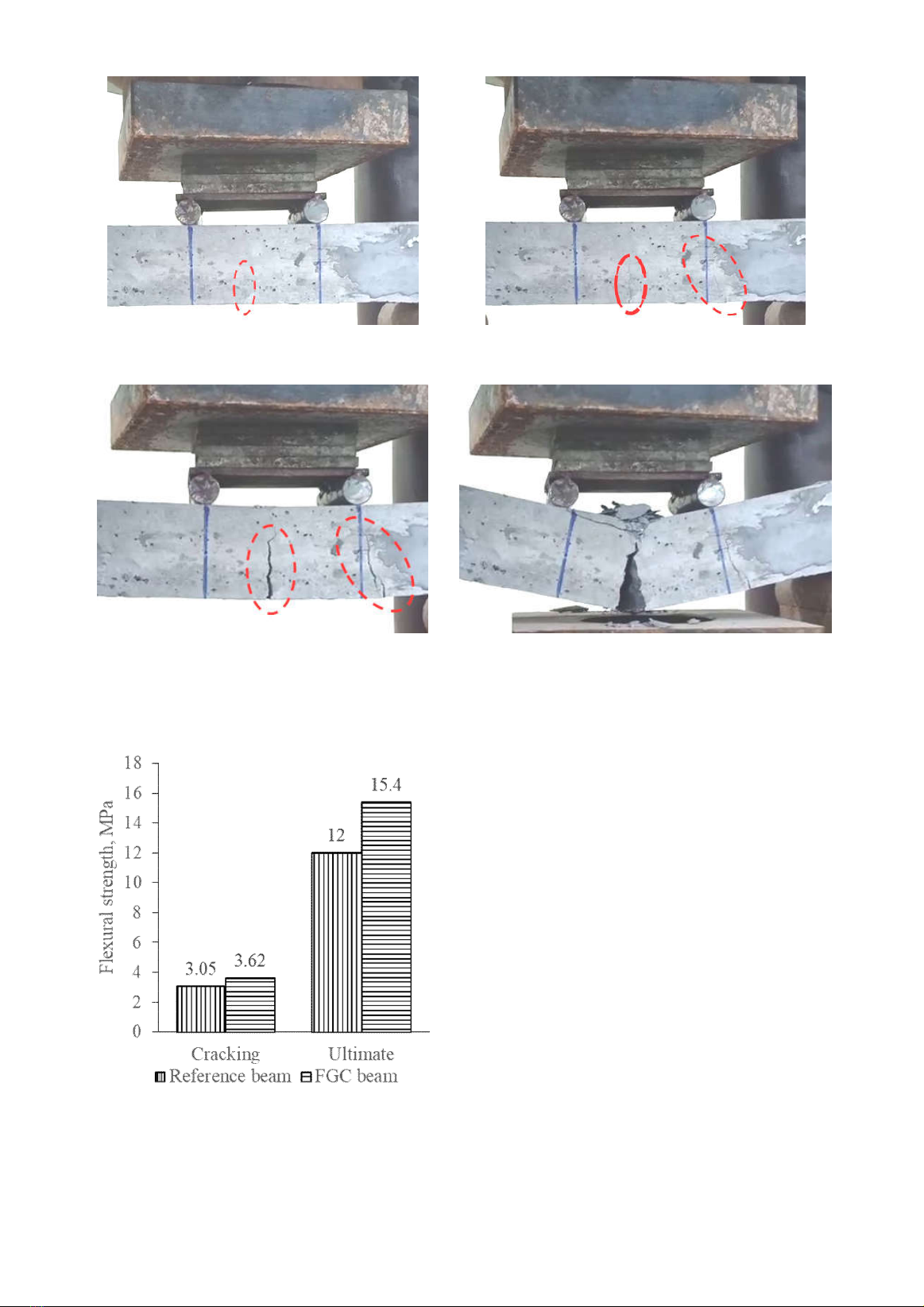
Figure 8. Crack propagation at the first stage
(point 1 in Figure 7)
Figure 9. Crack propagation at the second stage
(point 2 in Figure 7)
Figure 10. Crack propagation at the third
stage (point 3 in Figure 7)
Figure 11. Failure development at the final stage
(point 4 in Figure 7)
3.3. Flexural strength and failure mode
Figure 12. Cracking and ultimate
flexural strength of the reference and
FGC beam (mean value)
The mean values of cracking and ultimate
flexural strength obtained from the reference
and FGC beam are plotted in Figure 12. It can
be observed that cracking and ultimate strength
obtained from the latter is 19% and 28%
respectively higher than those from the former.
It indicates that the FGC beam performs better
than the reference beam under bending load
thanks to the application of the HPGFRC layer.
The FGC beam was scrutinized after the test.
The pull-out of glass fiber in the HPGFRC layer
was witnessed, as shown in Figure 13. The FGC
beam fails as same as the reference one. There is
no crack or delamination between the two layers
of conventional concrete and HPGFRC on the
FGC beam, as can be observed in Figure 14.
This point out that this kind of beam is viable and
applicable to many kinds of structures in