This simplified approach yields a “marginal” rat-
ing, whereas the more detailed analysis of figures
4–20 and 4–21 produces an “acceptable” rating for
the same structure. The detailed approach is nor-
mally preferred because it takes into account the
more specific design components, and, in this case,
includes the influence of the sound absorption ma-
terial in the corridor ceiling—which could just
about eliminate the noise excesses that appear in
item 12 of the figure 4-22 simplified analysis.
(d) A similar analysis carried out for the
right-side office and the secretary’s office would
show slightly lower sound levels because of the
smaller wall area facing the corridor. Thus, any
wall design that meets the acoustic requirement for
the left-side office will be acceptable for all other
spaces along the corridor.
(8) Vibration control for the offices. These of-
fices are located only about 20 ft. from the nearest
engines. This imposes fairly serious vibration isola-
tion requirements to meet the NC–40 low-
frequency sound levels in the offices. Paragraph
3–6 contains details of vibration isolation of
reciprocating engines. The vibration isolation
treatment should follow the recommendations giv-
en for a category 4 or 5 office or work space (N&V
table 3–2) located within 20- to 80-ft. distances of
the six large engines in this power plant. For such
close distances, there is no guarantee that NC–40
levels can be reached in the low-frequency octave
bands. Earthborne and structureborne vibration
decays slowly with distance (N&V para 4–l), espe-
cially at low frequency. If this were a critical prob-
lem, it would be advisable to move the offices to
greater distances from the power plant. In this
sample problem, it is assumed that the office occu-
pants are involved with the operation of the power
plant and would be receptive to a moderate amount
of noise and vibration.
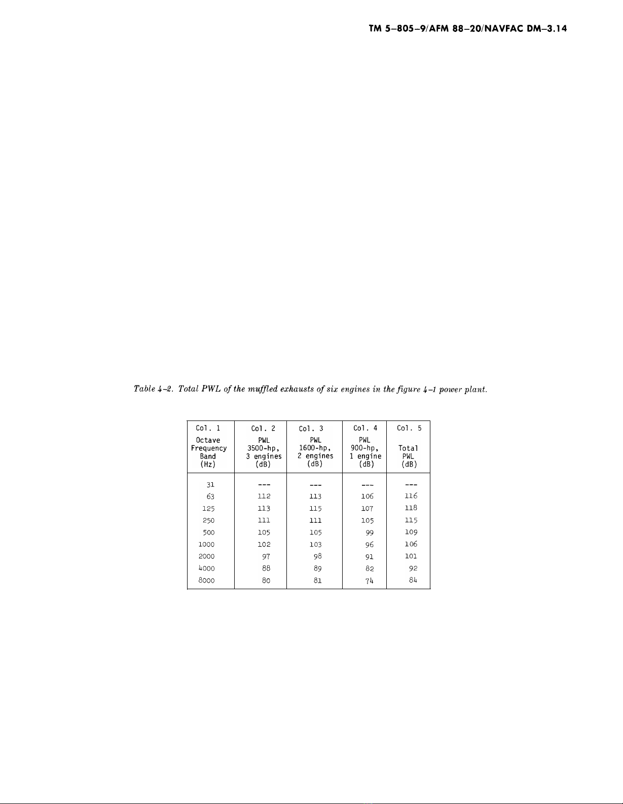
(9) Engine exhaust noise to on-base housing.
(a) On-base housing is to be located 1200 ft.
to the east of the power plant, and it is desired to
not exceed NC–25 sound levels indoors at the hous-
ing. PWLs of muffled engine exhausts are given in
figures 4–2 through 4–4. The top of each exhaust
pipe extends above the roof of the power plant and
is in unobstructed view of the housing. The PWLs
of the six engine exhausts are given in table 4–2.
The PWL contributions are obtained from Item 21 (Appendix B of the N&V manual describes “decibel
in figures 4–2, 4–3, and 4–4. Where two similar en- addition.”)
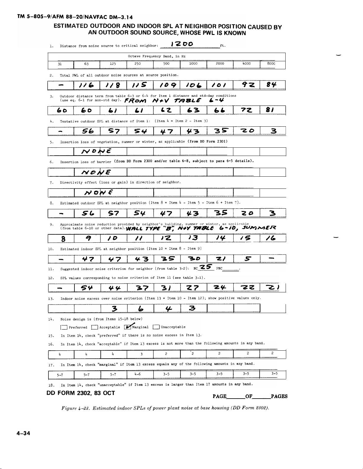
gines are involved, 3 dB are added to the levels of (b) SPLs inside the base housing are esti-
one engine (as in COl. 3, taken from fig. 4-4); and mated with the use of DD Form 2302 (Estimated
where three similar engines are involved, 5 dB are Outdoor and
added to the levels of one engine (as in COl. 2, taken Caused by an
from fig. 4–2). The total PWLs of all six engine ex- is Known). A
hausts are given in the last column of table 4-2. 4-23.
Indoor SPL at Neighbor Position
Outdoor Sound Source Whose PWL
sample calculation is given in figure
4-33
Simpo PDF Merge and Split Unregistered Version - http://www.simpopdf.com
Simpo PDF Merge and Split Unregistered Version - http://www.simpopdf.com
Item 13 shows an indoor noise excess of 3 to 6 dB in
the 125- to 1000-HZ octave bands. This would be
rated as “marginal”. If the NC–25 criterion is a
justified choice, these noise excesses should not be
permitted. A number of other factors could influ-
ence the decision. If the housing is exposed to
other uncontrollable excess noise (such as nearby
highway activity or base aircraft activity), power
plant noise might not appear so noticeable. How-
ever, if the base is located in a very quiet suburban
or rural area, with very little other noise, the pow-
er plant noise will be very noticeable. If the base is
located in a very hot or very cold region, year-
round, and the windows are kept closed most of the
time, and if inside sources, such as air conditioners
or central heating and cooling systems, are in near-
ly continuous use, external noise sources will not
be as noisy when heard indoors. These various con-
ditions could be used to support or justify adjust-
ments to the NC criterion. In the present problem,
it is assumed that such factors have already been
considered, and the NC–25 selection is a valid
choice.
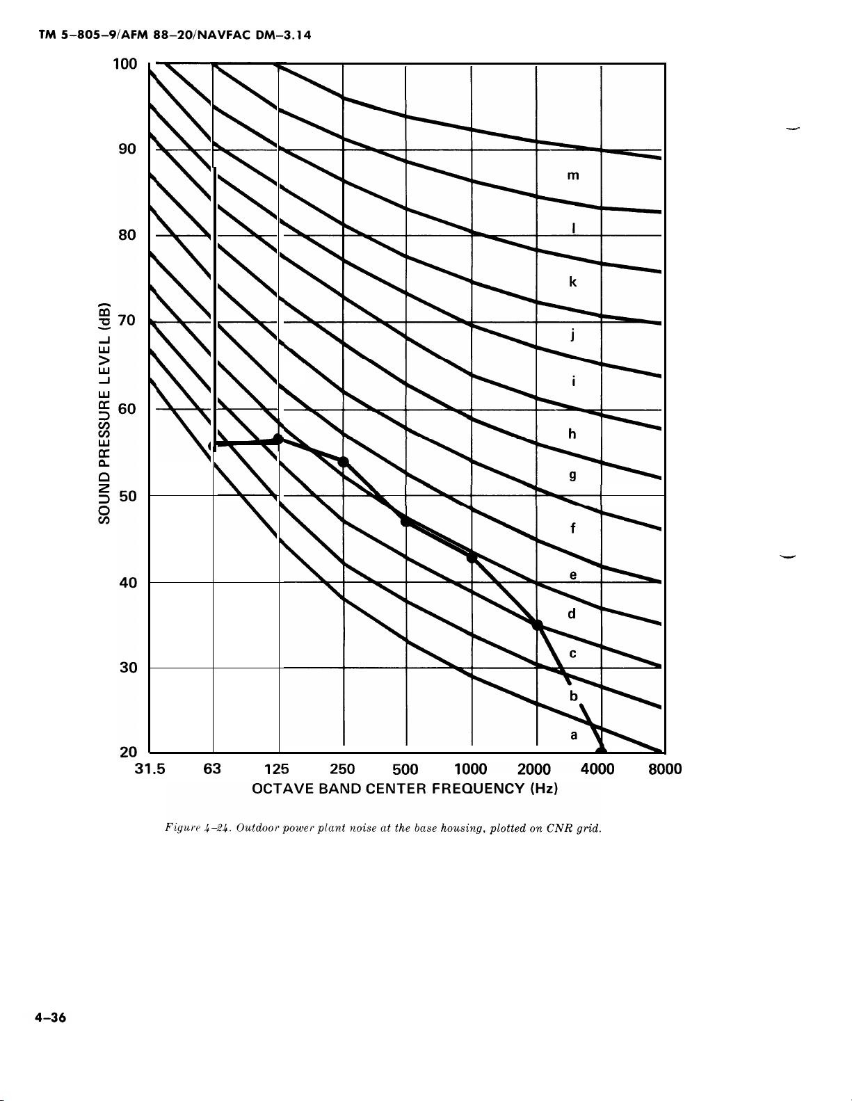
(c) A CNR analysis should be carried out as
a means of checking or confirming the expected re-
action of the housed personnel to the power plant
noise. The N&V manual (para. 3–3c) summarizes
the procedure. Figure 4–24 shows the CNR grid
upon which the outdoor power plant SPLs are
plotted (taken from Item 8 of fig. 4–23). A noise
level rank of “e” is obtained.
4-35
Simpo PDF Merge and Split Unregistered Version - http://www.simpopdf.com
Simpo PDF Merge and Split Unregistered Version - http://www.simpopdf.com

The N&V table 3–4 or figure 3–4 provides a means
of determining the correction number for the back-
ground noise in the area. If background noise
measurements can be made at the existing base,
N&V figure 3–4 should be used; otherwise the
background noise correction may be estimated by
selecting the most nearly applicable conditions of
N&V table 3–4. For this sample problem, a back-
ground noise correction of +1 is used. N&V table
3–5 is then used to determine other correction
numbers applicable to the problem. The following
corrections are here assumed:
Correction for temporal or seasonal factors
Day and night
o
Summer and winter
o
“On” full time
o
Correction for character of noise
No unusual sounds
o
Correction for previous exposure
Some previous exposure and good
community relations
o
Background noise correction
From discussion above +1
Total corrections +1
The CNR (composite noise rating) is then e + 1 =
F. The N&V figure 3–5 is used to estimate the ex-
pected community response, where base personnel
are assumed to be the equivalent of “average resi-
dents. ” A CNR value of F indicates a strong reac-
tion against the noise for the conditions assumed
here. A noise reduction of about 10 dB would bring
the reaction down to “sporadic complaints, ” which
might be considered a reasonable condition. CNR
values of C or D are often encountered in nonmili-
tary situations.
(d) On the basis of both indoor and outdoor
power plant noise at the base housing, the above
analyses strongly suggest the need for a 5- to
10-dB reduction of noise, with principal emphasis
on noise control in the 125- to 1000-HZ frequency
range.
(e) Several possibilities exist for reduction
of the excess noise. If the base has a large land
area and is not yet constructed, the power plant
and the housing area can be moved farther apart.
An increase in distance from 1200 ft. to 2000 ft.
would give a 250-Hz noise reduction of 5 dB, and an
increase in distance to 3000 ft. would give a 250-Hz
noise reduction of 10 dB (from N&V table 6–4). As
one alternative, the base housing can be designed
and constructed to have higher TL walls and closed
windows facing the power plant. This would reduce
indoor SPLs but would not change the outdoor
SPLs. If possible, other large buildings on the base
could be used to shield the housing area from the
power plant. Two feasible alternatives could be ap-
plied at the power plant. In one, special large-
volume, low-pressure-drop mufflers could be used,
either singly or in series, in the exhaust lines from
the engines to provide greater insertion loss than is
quoted in table 3–2 for the rather conventional
grades of mufflers. Such mufflers have been used
successfully with large engines located as close as
600 to 800 ft. from residential areas. As another al-
ternative, an outdoor L-shaped barrier wall ex-
tending above the top of the exhaust pipe openings
for the engines in Engine Room No. 1 could be
built above the second-floor Mechanical Equipment
Room and the south wall of the Engine Room to
give a beneficial amount of noise reduction for the
exhaust of the three 3500-hp engines. The exhaust
mufflers for the two 1600-hp engines could be
specified and purchased to have a larger amount of
insertion loss than assumed in the figure 4–4 analy-
sis. The 900-hp engine is the quietest one of the en-
tire group and may or may not need additional
muffling, depending on the success of the other
pursuits.
(10) Other engine noise to on-base housing.
(a) Turbocharger inlet noise for the three
outdoor inlets of the 3500-hp engines should be
checked for meeting the desired indoor and outdoor
levels of the base housing. The PWLs of the un-
muffled inlet of one such engine is given in Item 16
of figure 4–2. These levels should be increased by 5
dB (for three engines), then extrapolated to the
1200-ft. distance. The inlet openings are partially
shielded by the power plant building, and the bar-
rier effect of the building can be estimated. Ab-
sorbent duct lining in the air inlet ducts or dissipa-
tive mufflers at the intake to the air cleaners can
be very effective at reducing the high-frequency
tonal sounds of the turbochargers.
(b) Sound from Engine Room No. 2 can es-
cape from the open vent on the east wall of this
room and travel directly to the housing area. Fig-
ure 4–23 shows the principal steps in the analysis
of this part of the problem.
4-37
Simpo PDF Merge and Split Unregistered Version - http://www.simpopdf.com
![Bộ tài liệu Đào tạo nhân viên chăm sóc khách hàng tại đơn vị phân phối và bán lẻ điện [Chuẩn nhất]](https://cdn.tailieu.vn/images/document/thumbnail/2025/20251001/kimphuong1001/135x160/3921759294552.jpg)

![Thiết kế tụ điện và đi dây [chuẩn nhất]](https://cdn.tailieu.vn/images/document/thumbnail/2018/20180612/truonganhshun/135x160/9041528775303.jpg)

![Cân bằng công suất tác dụng và phản kháng trong hệ thống điện: Chương 11 [Hướng dẫn chi tiết]](https://cdn.tailieu.vn/images/document/thumbnail/2015/20150806/hoangnhu220191/135x160/753133488.jpg)
![Tài liệu lớp thực hành Thiết kế M&E [mới nhất]](https://cdn.tailieu.vn/images/document/thumbnail/2015/20150515/ducxt1995/135x160/1757147_269.jpg)


%20--%3e%3cdefs%3e%3cstyle%3e%20.st0%20{%20fill:%20%23fff;%20}%20.st1%20{%20fill:%20%237800fa;%20}%20%3c/style%3e%3c/defs%3e%3cpath%20class='st1'%20d='M117.78,12.18H43.11c2.9,3.47,4.65,7.94,4.65,12.82,0,5.6-2.3,10.66-6.01,14.29h76.02l7.22-13.56-7.22-13.56Z'/%3e%3cg%3e%3cpath%20class='st0'%20d='M53.58,26.17h-.59v-1.46h.59v-4.96h2.83c1.78,0,2.67.94,2.67,2.82v5.76c0,1.87-.89,2.81-2.67,2.81h-2.83v-4.96ZM55.36,21.37v3.34h1.1v1.46h-1.1v3.34h1.01c.61,0,.91-.37.91-1.1v-5.93c0-.74-.3-1.1-.91-1.1h-1.01Z'/%3e%3cpath%20class='st0'%20d='M65.99,31.14h-1.8l-.31-2.07h-2.19l-.31,2.07h-1.64l1.82-11.39h2.62l1.82,11.39ZM65.28,18.04c-.25.46-.51.77-.75.94-.21.15-.47.22-.79.22-.26,0-.57-.07-.92-.22l-.38-.15c-.14-.05-.26-.07-.37-.07-.3,0-.53.18-.71.54l-.91-.68c.25-.46.51-.77.75-.94.21-.14.48-.21.79-.21.26,0,.57.07.92.21l.38.15c.14.05.26.07.37.07.3,0,.53-.18.71-.54l.91.68ZM61.91,27.52h1.73l-.87-5.76-.87,5.76Z'/%3e%3cpath%20class='st0'%20d='M74.53,26.89v1.52c0,1.91-.89,2.86-2.67,2.86s-2.67-.95-2.67-2.86v-5.93c0-1.91.89-2.86,2.67-2.86s2.67.95,2.67,2.86v1.11h-1.69v-1.22c0-.75-.31-1.12-.93-1.12s-.93.37-.93,1.12v6.15c0,.74.31,1.11.93,1.11s.93-.37.93-1.11v-1.63h1.69Z'/%3e%3cpath%20class='st0'%20d='M81.4,31.14h-1.8l-.31-2.07h-2.19l-.31,2.07h-1.64l1.82-11.39h2.62l1.82,11.39ZM75.9,19.2l1.52-1.91h1.71l1.51,1.91h-1.61l-.76-.95-.75.95h-1.61ZM77.32,27.52h1.73l-.87-5.76-.87,5.76ZM83.1,15.99l-1.76,1.91h-1.26l1.17-1.91h1.86Z'/%3e%3cpath%20class='st0'%20d='M84.86,19.75c1.78,0,2.67.94,2.67,2.82v1.48c0,1.87-.89,2.81-2.67,2.81h-.85v4.28h-1.79v-11.39h2.64ZM84.01,21.37v3.86h.85c.58,0,.87-.36.87-1.08v-1.71c0-.71-.29-1.07-.87-1.07h-.85Z'/%3e%3cpath%20class='st0'%20d='M93.51,19.75c1.78,0,2.67.94,2.67,2.82v1.48c0,1.87-.89,2.81-2.67,2.81h-.85v4.28h-1.79v-11.39h2.64ZM92.66,21.37v3.86h.85c.58,0,.87-.36.87-1.08v-1.71c0-.71-.29-1.07-.87-1.07h-.85Z'/%3e%3cpath%20class='st0'%20d='M98.8,31.14h-1.79v-11.39h1.79v4.88h2.03v-4.88h1.83v11.39h-1.83v-4.88h-2.03v4.88Z'/%3e%3cpath%20class='st0'%20d='M105.36,24.55h2.46v1.62h-2.46v3.34h3.09v1.63h-4.88v-11.39h4.88v1.63h-3.09v3.18ZM108.17,17.29l-1.76,1.91h-1.26l1.17-1.91h1.86Z'/%3e%3cpath%20class='st0'%20d='M112.2,19.75c1.78,0,2.67.94,2.67,2.82v1.48c0,1.87-.89,2.81-2.67,2.81h-.85v4.28h-1.79v-11.39h2.64ZM111.35,21.37v3.86h.85c.58,0,.87-.36.87-1.08v-1.71c0-.71-.29-1.07-.87-1.07h-.85Z'/%3e%3c/g%3e%3ccircle%20class='st1'%20cx='25'%20cy='25'%20r='20'/%3e%3cpath%20class='st0'%20d='M32.78,19.27c2.92,0,4.43,2.55,5.28,5.33l.71,2.17c.14.38-.33.75-.71.75h-5.61c.19-.33.24-.71.09-1.08l-.75-2.45c-.43-1.32-.99-2.64-1.79-3.77.75-.57,1.65-.94,2.78-.94h0ZM25,18.38c3.25,0,4.9,2.78,5.89,5.89l.76,2.45c.14.42-.33.8-.8.8h-11.69c-.42,0-.94-.38-.8-.8l.75-2.45c.99-3.11,2.64-5.89,5.89-5.89h0ZM25,11.35c1.74,0,3.11,1.37,3.11,3.11s-1.37,3.11-3.11,3.11-3.11-1.41-3.11-3.11,1.41-3.11,3.11-3.11h0ZM17.27,19.27c1.08,0,1.98.38,2.73.94-.8,1.13-1.37,2.45-1.74,3.77l-.8,2.45c-.14.38-.05.75.09,1.08h-5.56c-.42,0-.9-.38-.75-.75l.71-2.17c.9-2.78,2.41-5.33,5.33-5.33h0ZM17.27,12.91c1.51,0,2.78,1.27,2.78,2.83s-1.27,2.83-2.78,2.83-2.83-1.27-2.83-2.83,1.27-2.83,2.83-2.83h0ZM32.78,12.91c1.56,0,2.78,1.27,2.78,2.83s-1.23,2.83-2.78,2.83-2.83-1.27-2.83-2.83,1.27-2.83,2.83-2.83h0ZM27.07,28.56v.09c0,.57-.24,1.08-.61,1.46h0v.05c-.38.33-.9.57-1.46.57s-1.08-.24-1.46-.61h0c-.38-.38-.61-.9-.61-1.46v-.09h1.41v.09c0,.19.05.38.19.47v.05c.09.09.28.19.47.19s.38-.09.47-.19v-.05c.14-.09.24-.28.24-.47t-.05-.09h1.41ZM30.99,28.56v.09c0,1.65-.66,3.16-1.74,4.24-1.08,1.08-2.59,1.79-4.24,1.79s-3.16-.71-4.24-1.79l-.05-.05c-1.04-1.08-1.7-2.55-1.7-4.2v-.09h1.41v.09c0,1.27.47,2.4,1.27,3.25h.05c.85.85,1.98,1.37,3.25,1.37s2.4-.52,3.25-1.37c.85-.8,1.37-1.98,1.37-3.25v-.09h1.37ZM34.99,28.56v.09c0,2.78-1.13,5.28-2.92,7.07-1.79,1.79-4.29,2.92-7.07,2.92s-5.23-1.13-7.07-2.92c-1.79-1.79-2.92-4.29-2.92-7.07v-.09h1.41v.09c0,2.4.94,4.53,2.5,6.08,1.56,1.56,3.72,2.5,6.08,2.5s4.52-.94,6.08-2.5c1.56-1.56,2.5-3.68,2.5-6.08v-.09h1.41Z'/%3e%3c/svg%3e)