Hindawi Publishing Corporation
EURASIP Journal on Applied Signal Processing
Volume 2006, Article ID 42737, Pages 1–11
DOI 10.1155/ASP/2006/42737
A New Position Location System Using DTV Transmitter
Identification Watermark Signals
Xianbin Wang,1Yiyan Wu,1and Jean-Yves Chouinard2
1Communications Research Centre Canada, 3701 Carling Avenue, Ottawa, Canada ON K2H 8S2
2Department of Electrical and Computer Engineering, Laval University, Canada QC G1K 7P4
Received 30 May 2005; Revised 30 January 2006; Accepted 9 March 2006
A new position location technique using the transmitter identification (TxID) RF watermark in the digital TV (DTV) signals is
proposed in this paper. Conventional global positioning system (GPS) usually does not work well inside buildings due to the high
frequency and weak field strength of the signal. In contrast to the GPS, the DTV signals are received from transmitters at relatively
short distance, while the broadcast transmitters operate at levels up to the megawatts effective radiated power (ERP). Also the RF
frequency of the DTV signal is much lower than the GPS, which makes it easier for the signal to penetrate buildings and other
objects. The proposed position location system based on DTV TxID signal is presented in this paper. Practical receiver imple-
mentation issues including nonideal correlation and synchronization are analyzed and discussed. Performance of the proposed
technique is evaluated through Monte Carlo simulations and compared with other existing position location systems. Possible
ways to improve the accuracy of the new position location system is discussed.
Copyright © 2006 Xianbin Wang et al. This is an open access article distributed under the Creative Commons Attribution License,
which permits unrestricted use, distribution, and reproduction in any medium, provided the original work is properly cited.
1. INTRODUCTION
Geographic location information can be retrieved by various
infrastructures and technologies. The most popular position
location system is the global position system (GPS) based on
a constellation of about 24 satellites orbiting the earth at alti-
tudes of approximately 11,000 miles [1]. In Europe, a satellite
navigation system named Galileo was deployed by the Euro-
pean Commission and Space Agency based on a 30-satellite
constellation, to provide positioning and timing services in
2008 [2]. Uncorrected positions determined from GPS satel-
lite signals produce accuracies in the range of 50 to 100 me-
ters. When using a technique called differential correction,
users can get positions accurate to within 5 meters or less.
GPS is effective and accurate outdoors, but it works very
poorly, if at all, indoors and in urban canyon environments,
and a reliable solution is needed to fill these gaps in coverage.
Moreover, GPS is vulnerable to jamming and other disrup-
tions from manmade and natural causes. Without a func-
tional backup, widespread disruption of the GPS would be
catastrophic for commercial applications, as well as domestic
and international security.
New alternative position location systems were recently
proposed based on other wireless communication systems,
such as cellular networks and wireless LAN. An order issued
by the U.S. Federal Communications Commission (FCC) in
July 1996 requires that all wireless service providers, includ-
ing cellular and broadband wireless, provide location infor-
mation to Emergency 911 (E-911) public safety services [3].
These new FCC E-911 requirements have also boosted re-
search in wireless location techniques. Cellular networks can
be used to provide location services, where the mobile sta-
tions are located by measuring the signals traveling to and
from a set of fixed cellular base stations. However, owing to
the low power of each transmitter and narrow bandwidth,
position systems based on cellular networks can only achieve
very limited accuracy with locationing error often larger than
few hundred meters [4,5]. With the development of wire-
less local area networks (LAN), there is an increasing level
of interest in developing the technology to geolocate using
DSSS/OFDM based wireless LAN systems [6]. Position loca-
tion system based on wireless LAN is more accurate within
the service area of network. However, its application is lim-
ited by the network coverage and outdoor locationing infor-
mation is often unavailable especially for rural areas. Posi-
tioning system using television synchronization signals was
first proposed in [7]. The major advantage of the television
locationing approach is from the low RF frequency, wide
band, high transmission power, and broad coverage of DTV
transmitters. However, a network of monitor stations has to

2 EURASIP Journal on Applied Signal Processing
be established to broadcast the timing information for each
TV station.
In this paper, a new position location system is proposed
based on DTV transmitter identification watermarks. Train-
ing sequence in DTV signals might be used for position lo-
cation and multipath estimation under some circumstances.
However, large position location error may be introduced
when there is cochannel interference in the DTV signal. In
the presence of cochannel interference, multipath estimation
is actually the linear combination of the multipath chan-
nel responses from all the DTV transmitters on the same
channel, since an identical training sequence is used for all
cochannel DTV transmitters. In addition, TxID watermark
is still needed to identify the transmitter location and propa-
gation time. As a result, the proposed DTV position location
system and the subsequent analysis are based on the trans-
mitter identification watermark.
As of May 2005, there are more than 1400 terrestrial dig-
ital television (DTV) transmitters in operation in the U.S.A.,
Canada, and Mexico. The Advanced Television System Com-
mittee (ATSC) DTV signals are entirely different from the
analog TV signals and have many new capabilities. One in-
teresting new feature of the ATSC signal is that a pseudoran-
dom sequence, used as an RF watermark, can be uniquely
assigned to each DTV transmitter for transmitter identifica-
tion (TxID) purpose [8]. Due to an ever-increasing number
of DTV transmitters, the need for transmitter identification
is becoming essential since it enables the broadcast authori-
ties and operators to identify the source of in-band interfer-
ences. In [8], phase modulation of each TxID sequence can
also lead to a robust data transmission approach, which can
be used to broadcast the timing and geolocation informa-
tion for each transmitter. Similar transmitter identification
techniques could also be used to DVB-T system in the fu-
ture. Using relatively simple signal processing, DTV signals
from different transmitters can be identified. By varying the
phase of the TxID sequence, the timing and location infor-
mation for each DTV transmitter can also be sent out. Since
the locations of the DTV transmitters are known, it is pos-
sible to locate the receiver positions when the DTV signals
from multiple DTV transmitters can be successfully received
and identified.
The proposed position location process using DTV TxID
or watermarked signal, can be realized through several steps.
(1) Identify the sources for all DTV signals received at one
location. This is based on the calculation of cross-correlation
between the DTV signals and local TxID sequences. The
ATSC field SYNC signal can be used for a quick synchroniza-
tion of the TxID sequence. (2) Calculate the pseudorange be-
tween the receiver and each DTV transmitter. (3) Determine
the coordinates of the receiver by solving a nonlinear equa-
tion system. When there are more transmitters than needed
for location position, optimization techniques can be used to
increase the positioning accuracy and reduce the impact of
multipath distortion.
The rest of the paper is organized as follows: transmit-
ter identification using RF watermark is elaborated in Sec-
tion 2. The proposed position location technique using TxID
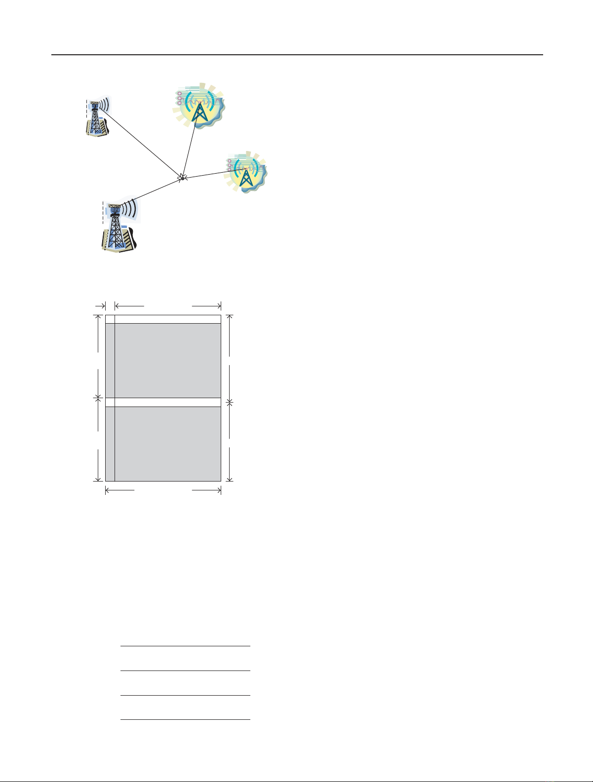
+
TxID sequences
ATSC field sync.
ATSC data
(a)
30 dB
(b)
Figure 1: Illustration of the ATSC DTV signal with the embedded
spread spectrum sequences. (a) Time domain, (b) frequency do-
main.
watermark is presented in Section 3. Practical implementa-
tion issues including the nonideal cross-correlation function
and synchronization for the position location receiver is an-
alyzed and discussed in Sections 4and 5,respectively.Nu-
merical results for the proposed position technique were pre-
sented in Section 6. Example of position location using a
nonlinear equation system was also given in this section. The
paper is finally summarized in Section 7.
2. TRANSMITTER IDENTIFICATION FOR DTV
The proposed position location is achieved based on multi-
ple distance measurements between known reference points,
that is, signals from different DTV transmitters have to be
identified for the determination of the geographic coordi-
nates. In [9], we proposed a transmitter identification system
using embedded pseudorandom sequences. A unique PN se-
quence is assigned to each individual transmitter in our pro-
posal and different transmitters are identified based on the
orthogonality between different sequences. The magnitude
of the pseudorandom sequence is carefully selected such that
the impact on the DTV reception is negligible. This proposal
has been adopted in the ATSC synchronization standard for
distributed transmissions [8], where a Kasami sequence with
aperiodof2
16 −1 is used for DTV transmitter identifica-
tion. The autocorrelation function of this sequence provides
42 dB dynamic range for transmitter identification [10,11].
The principle of the transmitter identification is illustrated in
Figure 1 both in frequency and time domain. A similar TxID
technique can also be applied to DVB-T systems. Denote the
DTV signals for the ith transmitter before and after the injec-
tion of the pseudorandom sequence xi(n)asdi(n)anddi′(n),
respectively. The injected process is
di′(n)=di(n)+ρxi(n), (1)

Xianbin Wang et al. 3
where ρis a gain coefficient to control the injection level
of the identification sequence, which can be different from
transmitter to transmitter. However, it will be convenient for
the identification process if the gain is the same for all the
transmitters. After passing through the channel hi, the re-
ceived signal from the ith transmitter, ri, can be formulated
as
ri(n)=di′(n)⊗hi+w(n), (2)
where w(n) is the additive white Gaussian noise (AWGN) of
the receiver. To identify the existence of the ith transmitter,
the cross-correlation between ri(n) and the locally generated
xi(n) has to be calculated:
Rrxi(m)=
N−1
n=0
r(n)xi(n−m)
=
N−1
n=0di(n)+ρxi(n)⊗hi+wi(n)·xi(n−m)
=ρRxixi⊗hi+N−1
n=0
di(n)xi(n−m)⊗hi
+
N−1
n=0
wi(n)xi(n−m),
(3)
where Nis the length of the transmitter identification water-
mark xi(n). The first term on the last line of (3), that is, the
autocorrelation function Rxixi, exists only when watermark
signal ρxi(n) is found in the received signal. The existence of
the ith transmitter can then be determined by the correlation
peak in (3) since the watermark signal ρxi(n) is uniquely as-
sociated with the ith transmitter. Equation (3) also indicates
that the correlation peak in the first term on the last line un-
dergoes the same attenuation and channel distortion as the
DTV signal described by the second term. To evaluate the
robustness of transmitter identification process, a simplified
AWGN channel model is applied to (3):
Rrxi(m)=AρRxixi+A
N−1
n=0
di(n)xi(n−m)
+
N−1
n=0
wi(n)xi(n−m),
(4)
where Ais a constant associated with the path loss. Due to
the large Nfor transmitter identification sequence, central
limit theorem can be applied to the second and third items
in (4), whose variances can be determined as NA2σ2
dand
Nσ2
w,whereσ2
dand σ2
ware the variances of the DTV signal
and AWGN noise. The signal-to-interference-and-noise ra-
tio (SINR) of the autocorrelation peak for transmitter iden-
tification in (4) can be determined as
SINR =10 log10 A2ρ2N2
NA2σ2
d+nσ2
w
=10 log10 N−10 log10 A2σ2
d+σ2
w
A2ρ2
=10 log10 N−10 log10 A2σ2
d1+σ2
w/A2σ2
dA2ρ2.
(5)
Equation (5) can be further arranged as
SINR =10 log10 N−10 log10 σ2
d
ρ2
−10 log10 1+ σ2
w
A2σ2
d.
(6)
Note that the second term in (6) is the injection ratio of the
transmitter identification watermark and σ2
w/A2σ2
dis the in-
verse of the signal-to-noise ratio (SNR) of the received signal,
which makes the third item in (6) negligible for any reason-
able SNR, that is, σ2
w/A2σ2
d≪1. Because the TxID water-
mark is inserted at a certain power level proportional to DTV
signal, the fixed relationship is maintained after both signals
pass through the same multipath channel. Additive Gaussian
noise from the receiver has virtually no impact on the TxID
process, unless the received signal is significantly weaker than
the noise introduced by the receiver, that is, the DTV signal
is under the receiver’s noise floor. Due to the extremely high
transmission power of DTV stations and the short distance
between the receiver and transmitter, (6) holds even for the
reception sites inside buildings since the excess path losses
due to the building penetration is usually around 10 ∼20 dB
[12,13]. As a result, the robustness of the transmitter iden-
tification process is dominated by the first two items in (6).
For the TxID system in [8], SINR in (6)is18dBwhenone
Kasami sequence is used, or 24 dB when four Kasami se-
quences in one field are combined for transmitter identifi-
cation. Considering the high transmission power of the DTV
stations, the coverage limitation for the transmitter identifi-
cation and the proposed position location is the shape of the
earth, rather than the signal strength of the DTV signal.
As we will explain in the next section, four DTV stations
are needed for position location purpose. These stations can
be on different channels. The position location receiver will
scan different TV channels for the DTV stations used for po-
sition location. In this situation, the analysis in (1)–(6)can
be directly applied to each station. The impact of the cochan-
nel interference from the DTV stations on the same channel
with different programs is limited since the coverage of these
DTV stations are well separated through the DTV stations
planning process. The other scenario for cochannel interfer-
ence is from DTV stations broadcasting the same program
on the same channel due to the deployment of the single fre-
quency network (SFN), in which same content is broadcasted
from different stations on the same frequency to save spec-
trum [14]. Cochannel DTV stations in SFN could be used as

4 EURASIP Journal on Applied Signal Processing
position location references, since different transmitter iden-
tification numbers [8] are assigned to different SFN stations.
However, the strength of the TV signals at one given location
from different SFN stations can vary significantly due to the
different distances from the receiver as well as the different
propagation environment. It is therefore very important to
analyze the robustness of the transmitter identification un-
der this circumstance since the combined DTV signals from
different SFN transmitters will interfere with the transmitter
identification process. The overall received signal r(n)canbe
reformulated as
r(n)=
M
i=1di′(n)⊗hi+w(n),(7)
where Mis the total number of TV signals from the SFN.
The existence of the jth transmitter is unknown without any
further identification process. Details of the existence and
strength of each specific transmitter at the reception site can
be achieved by calculating a correlation function. For in-
stance, cross-correlation between r(n)andxj(n) can indicate
the existence and provide strength information about the jth
transmitter:
Rrxj(m)=ρRxjxj⊗hj+
M
i=1,i=j
ρRxixj⊗hi
+
N−1
n=0
M
i=1di(n)⊗hixj(n−m)
+
N−1
n=0
w(n)xj(n−m).
(8)
With the orthogonal property of the selected pseudorandom
sequence, Rxjxjcan be approximated as a delta Kronecker
function. The second term can be neglected since differ-
ent transmitter identification sequences are orthogonal. The
third item in (8) is the combined interference from the SFN
DTV signals of the jth transmitter and the other transmit-
ters. Therefore, the received channel response hjfrom the
jth transmitter can be approximated by Rrxj. An interference
analysis for (8) with AWGN channel model lead to
SINR =10 log10 N−10 log10 σ2
d
ρ21+
M
i=1, i=j
A2
i
A2
j
−10 log10 1+ σ2
w
M
i=1A2
iσ2
d.
(9)
Comparing (6)and(9), the impact of the cochannel sta-
tions in SFN environment can be evaluated by the second
term in (9). When the cochannel DTV signal is stronger
than the signal from the particular station under identi-
fication process, the robustness of transmitter identifica-
tion is reduced. However, around 10 dB stronger cochan-
nel DTV signals can be tolerated due to the large margin in
the transmitter identification system [8,9]. Simple averag-
ing of the transmitter identification results in that the time
domain would reduce the impact of the DTV interference by
10 log10 P,wherePis the number of averaging. The complex-
ity associated with averaging is minimal since different DTV
signal segments for TxID can be averaged first before the
cross-correlation. Further performance improvement can be
achieved by the DTV signal cancellation approach. However,
the complexity of position location receiver will be increased
since the DTV signal has to be reconstructed based on the
demodulation result.
3. TIME-BASED POSITION LOCATION
USING TxID SIGNAL
Thereareseveraldifferent approaches to determine the lo-
cation of receiving devices in a wireless network, ranging
from direction-of-arrival detection to calculation of signal
strength loss. The technique considered in this paper is
based on triangulation. This method derives its name from
trigonometric calculations and can be done via lateration,
which uses multiple distance measurements between known
points, or via angulation which measures an angle or bearing
relative to points with known separation. These two tech-
niques are also referred to as direction-based and distance-
based techniques. Direction-based techniques measure the
angle of arrival (AOA) using antenna array. Because this AOA
triangulation technique requires the use of special anten-
nas, it would not be suitable for position location applica-
tions. Distance-based techniques involve the measurement
and calculation of the distance between a receiver and one or
more transmitters whose locations are known. The distance-
based technique uses one, or more, of the following signal at-
tributes: signal arrival time, signal strength, and signal phase.
If one measures the precise time a signal leaves a transmitter
and the precise time the signal arrives at a receiver, he can
determine the time of arrival (TOA); the time it takes for the
signal to reach the receiver.
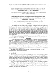
Consider four transmitters and the positioning receiver
shown in Figure 2. The coordinates of the four transmit-
ters are (x1,y1,z1), (x2,y2,z2), (x3,y3,z3), and (x4,y4,z4), re-
spectively. For existing DTV transmitters, these coordinates
are known to the positioning receivers. With the help of
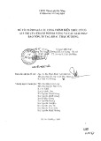
the embedded watermarks and the DTV field sync shown in
Figure 3, the propagation time for the DTV signal from each
DTV station can be easily determined. Denoting the propa-
gation time from the ith transmitter to the positioning recep-
tion point as ti, the simplified positioning algorithms without
errors can be formulated as
t1c=x−x12+y−y12+z−z12,
t2c=x−x22+y−y22+z−z22,
t3c=x−x32+y−y32+z−z32,
t4c=x−x42+y−y42+z−z42,
(10)
where cis the constant for light propagation velocity. Four
Xianbin Wang et al. 5
Tx A(x1,y1,z1)
Tx D(x4,y4,z4)
Tx B(x2,y2,z2)
Tx C(x3,y3,z3)
(x,y,z)
a
b
c
d
Figure 2: Position location system using DTV transmitters.
4 828 symbols
Field sync. #1
313
seg.
313
seg.
Segment sync.Segment sync.
Field sync. #2
832 symbols
24.2ms
24.2ms
Figure 3: One frame of ATSC signal with embedded TxID sequence
(shaded region).
transmitters are needed to find the coordinates of the posi-
tioning receiver when the absolute propagation time for each
transmitter is not available. In this case, what is known from
the received signal of the synchronous transmitter network
is the relative propagation time, with a common reference
timing related to the transmission network. Under this cir-
cumstance, (10)canberewrittenas
t1′c=x−x12+y−y12+z−z12,
t2′c=x−x22+y−y22+z−z22,
t3′c=x−x32+y−y32+z−z32,
t4′c=x−x42+y−y42+z−z42,
(11)
where ti′=ti−∆tis the absolute transmission time for the
ith transmitter with ∆tbeing the timing difference between
the receiver reference time and the absolute time. The value
of ∆tis unknown but identical for all transmitters since they
are all synchronized within the distributed transmitter net-
work. The pseudorange equation in (11) can be solved by the
technique in [15] without errors or by linearizing techniques
in [16] in the presence of errors.
As indicated in (11), the relative propagation time from
each transmitter to the positioning receiver has to be deter-
mined. The existence and the strength of each specific trans-
mitted signal rjfrom the jth transmitter at a given reception
site can be achieved by calculating correlation functions. For
example, the correlation between r(n) and a locally gener-
ated identification signal xj(n) can provide the existence and
strength of the jth transmitter using (8). Due to the orthog-
onal property of the selected sequence, Rxjxjcan be approxi-
mated as a delta function. The second and third terms in (8)
are only noise-like sequences from the in-band DTV signals
of the same transmitter and other transmitters. Therefore,
the channel response hjfrom the jth transmitter can be ap-
proximated by Rrxj, that is,
Rrxj(m)=Ahj+ noise, (12)
where Ais a constant determined by Rxjxjand the gain coef-
ficient ρ. The channel response hjfor the jth transmitter can
be determined, as Rxjxjand ρare known. The earliest corre-
lation peak that exceeds a particular threshold is correspond-
ing to the direct propagation path from the DTV station to
the position location receiver. The arrival time of the earli-
est correlation peak can then be converted to relative prop-
agation time in terms of seconds. The correlation functions
in (12) can be interpolated to improve the precision of the
propagation time determined. The threshold for each DTV
station is decided by the DTV station transmission power,
the approximate distance between the DTV station and the
receiver decided by the propagation time of the main path,
and the maximum expected excess path loss to the DTV sig-
nal due to the building penetration.
The main path of the autocorrelation function in (12)is
always used for transmitter identification due to its strongest
signal power. The distance between the DTV station and the
position location receiver depends only on the first arrived
path. However, the strength of the first arrived signal some-
timesisveryweak,anditisdifficult to discriminate multi-
path echoes from interference. In this case, the main path can
always be used as a timing reference for averaging a number
of adjacent transmitter identification results due to the slow
variation of the DTV signals. Simple averaging of the trans-
mitter identification results in the time domain would reduce
the impact of the DTV interference by 10 log10 P,whereP
is the number of averaging. The complexity associated with
averaging is minimal since different DTV signal segments
for TxID can be averaged first before the cross-correlation.
An average of 42 fields of DTV signal within one second
(168 Kasami sequence ) will provide 22 dB gain. Very weak
path such as −30 dB echo can be easily identified when the


![Thuyết minh tính toán kết cấu đồ án Bê tông cốt thép 1: [Mô tả/Hướng dẫn/Chi tiết]](https://cdn.tailieu.vn/images/document/thumbnail/2016/20160531/quoccuong1992/135x160/1628195322.jpg)