
* Corresponding author.
E-mail addresses: vadiati@ut.ac.ir (A. Vadiati)
© 2018 Growing Science Ltd. All rights reserved.
doi: 10.5267/j.esm.2018.5.003
Engineering Solid Mechanics 6 (2018) 241-252
Contents lists available at GrowingScience
Engineering Solid Mechanics
homepage: www.GrowingScience.com/esm
Design, control, and prototyping of a series elastic actuator for an active knee orthosis
Alireza Vadiatia*, Ahmad Bagheria, Mohammad Mahjooba,b and Mohammad J. Sadigha
aSchool of Mechanical Engineering, College of Engineering, University of Tehran, Tehran, Iran
bHarvard Medical School, Harvard university, Cambridge, Massachusetts, USA
A R T I C L EI N F O A B S T R A C T
Article history:
Received 10 January, 2018
Accepted 10 May 2018
Available online
10 May 2018
The use of elastic elements in actuators can be effective in improving their performance. The
present paper examines the different layouts of the elastic element in actuators, choosing the
appropriate design, and then designing a series elastic actuator for use in an active knee
orthosis. For this purpose, the design elements of actuators were extracted using the knee data
for walking. In the next step, considering the effect of the spring stiffness on the energy
consumption and actuator’s peak power, its optimum amount for gait was calculated.
Afterwards, the effect of adding the spring has been shown at an optimal value. Since the
human knee in a gait cycle involves position and force control, designing an efficient controller
to track the force and position of the knee during the gait cycle is the next section of this study.
Due to the specific application of this actuator, its volume and size are important for the user.
For this reason, it is necessary to design and construct an actuator with a suitable size and
weight, with good output. For this purpose, a lightweight and low volume actuator was
fabricated.
© 2018 Growing Science Ltd. All rights reserved.
Keywords:
Series elastic actuator
Active knee orthosis
Energy consumption
Peak power
Optimization
1. Introduction
War, accidents, illness and genetics are among the factors that cause disability. According to
statistics released in 2015, in the United States, 7% of the population, that is about 22.5 million, are
suffering from Ambulatory Disability (Erickson et al., 2016). One of the most common types of lower
limb disability is the inability to walk correctly due to a knee joint failure. The failure in the
performance of this joint, in addition to causing severe pain while walking, leads to a reduction in the
speed and function of the disabled person and his imbalance. The use of an orthosis is one of the
common ways to help people with impaired walking. These devices make it easier for the person to use
that limb, by helping the person in controlling the particular limb. Although an inactive orthosis helps
the person with disabilities to use their body, they also have limitations. On the other hand, injured
people who attend rehabilitation sessions after the incident, due to excessive pressure and fatigue, have
meetings shorter than one hour, also, between the two sessions of practice, the patient walks with the
pattern that he/she is accustomed to it. This increases the duration of treatment and reduces the
effectiveness of training sessions.
242
The use of an active orthosis with a controllable actuator in addition to speeding the process of
improving the walking pattern and rehabilitation process, can be effective in restoring the daily lives
of affected individuals. The purpose of this research is designing and building an active orthosis with
an acceptable weight and size for the knee joint, which, in addition to helping the injured in training
sessions, also has the ability to be used outside the clinical environment for daily routine affairs. The
focus of this study is on the use of a series elastic actuator to optimize energy consumption and peak
power in addition to better interaction with the body due to its low mechanical impedance and power
to weight ratio. Pratt et al first introduced an exoskeleton for the knee that takes advantage of a series
elastic actuator (Pratt et al. 2004).
In many cases an active orthosis for the knee has the task of teaching and accompanying the patient
in rehabilitation exercises (Weinberg et al., 2007). In this case the orthosis was created by means of a
brake fluid that provided the torque required to prevent knee bending in the stance state. Researchers
in the Laboratory of Biomedical Robotics and Biomicrosystems have introduced a torsional series
elastic actuator for a knee orthosis (Sergi et al., 2012). The torsional spring of this actuator has been
designed and built for this purpose. Yu and colleagues have introduced a knee-ankle foot orthosis for
stroke patients and for outside the clinical environment (Yu et al., 2013). Hassani and his colleagues
also presented a knee active orthosis designed to help in training sessions (Hassani et al., 2014). Shan
and colleagues have introduced a knee active orthosis to help walking that uses electromyography
signals, they showed that the active orthosis helps reduce muscle activity (Shan et al., 2016). In the
remainder of this article and in the second section, we will examine different actuator layouts and select
the appropriate actuator. Then we try to design the selected actuator. The means by which the orthosis
is controlled is also presented in the third part. In the fourth section, the results are presented and in the
final section the conclusions of the work and suggestions are presented.
2. Methods
Elastic tissues, such as tendons, ligaments, and muscle, play an essential role in optimal energy use
and body balance during walking (Ker et al., 1987; Blickhan, 1989; Cavagna et al., 1977; Farley et al.,
1993; Hogan, 2002; McMahon, & Cheng 1990). The human body uses these elements to compensate
for some of the energy lost when it collides with the ground by absorbing and storing energy and
releasing it at the time of the removal of the leg. This is an inspiration to many designers of orthotics
and prosthetics that use elastic elements to reduce the walking metabolism (Elliott & Herr 2012).
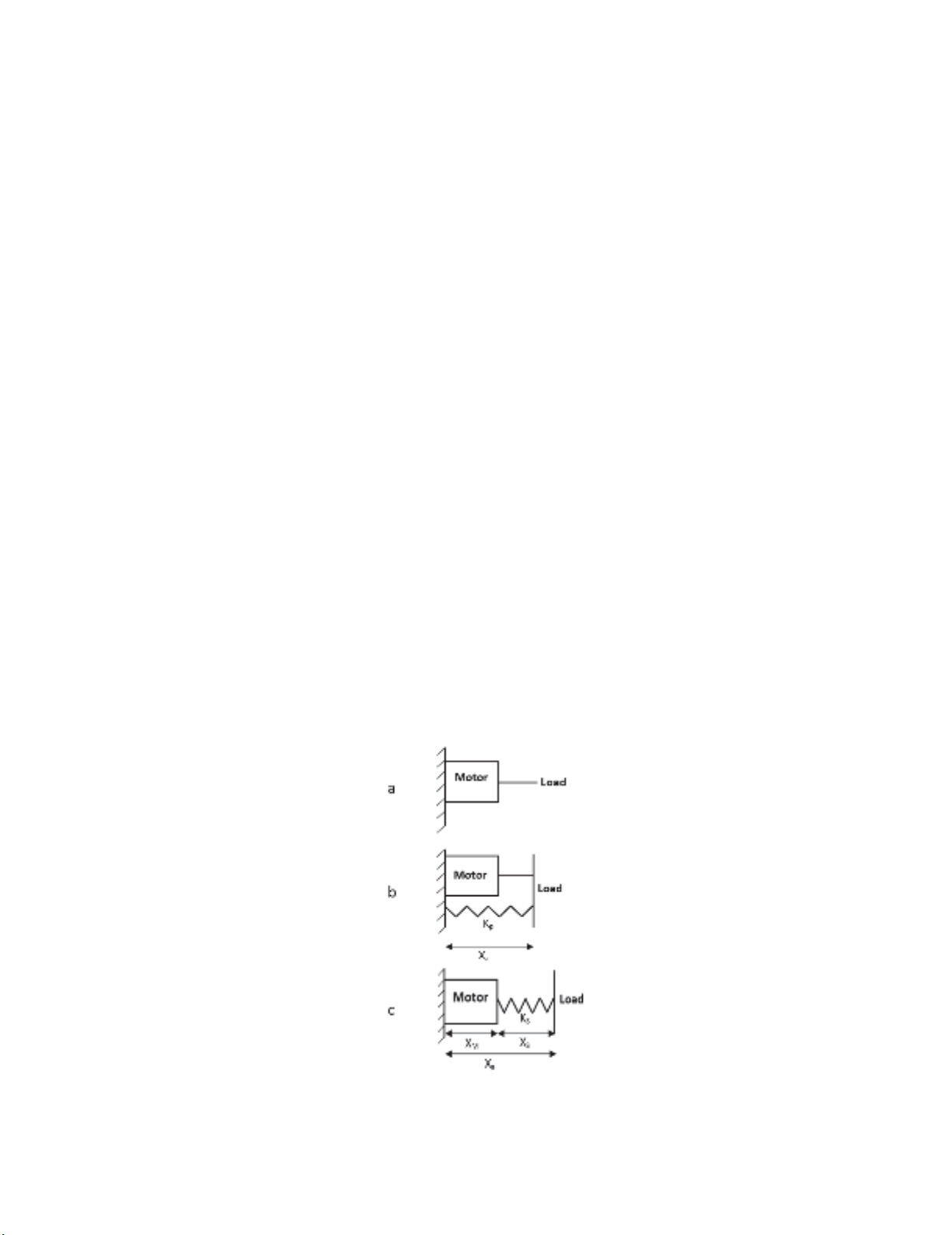
Fig. 1. Schematic view of different actuator layouts; (a) Direct Drive; (b) Parallel Elastic
actuator; (c) Series Elastic actuator.

A. Vadiati et al. / Engineering Solid Mechanics 6 (2018)
243
2.1. Spring optimization
In this section, we first examine three layouts including: Direct Derive (DD), Parallel Elastic
Actuator (PEA) and Series Elastic Actuator (SEA). Fig. 1 shows the schematic of these three layouts.
The criterion for selecting the optimal actuator is the peak power and energy consumption. The
peak power for direct drive is obtained from
∙, (1)
where is the motor power, is the knee force and is the rate of actuator length change.
Also the power for the series and parallel actuator is calculated from Eq. (2) and Eq. (3)
respectively; is the parallel spring stiffness and ∆ is the spring length change.
∙∆∙ (2)
(3)
The next criterion is the orthosis energy consumption. Power is used to calculate the energy (E).
|| (4)
The reason for using the absolute value of the power in Eq. (4) is that the DC Motor needs power
for both pushing and resistance to movement. In Eq. (1), parameters and are obtained from the
walking geometry and clinical data, and as a result, the energy required is dependent on . In the next
step, in order to find the optimal value of the spring constant for reducing energy consumption and
maximum power in each actuator state the spring constant was changed from 1 kN/m to 1000 kN/m
with steps of 1 kN/m, and the amount of power and energy consumption of the orthosis for the various
stiffness coefficients of the spring were calculated in each mode. The results show that a series elastic
actuator during walking has a better performance than the other two layouts.
2.2. Design
A commercial sample of a Knee Brace is used to connect the actuator to the knee. A sliding
potentiometer was used to calculate the displacement of the spring and consequently the actuator output
force. This potentiometer shows the displacement with an accuracy of 0.1 mm. The Power of this
actuator is taken from a 100-watt BLDC from Maxon's EC-4pole series. The 7075-T651 aluminum
alloy has been used to reduce the weight of the actuator, whose ultimate strength is close to steel and
has a density of about one third of the steel. Using the knee data, the maximum force of the actuator
was calculated to be 1050 N for compression and 800 N for tension. The actuator’s plates were
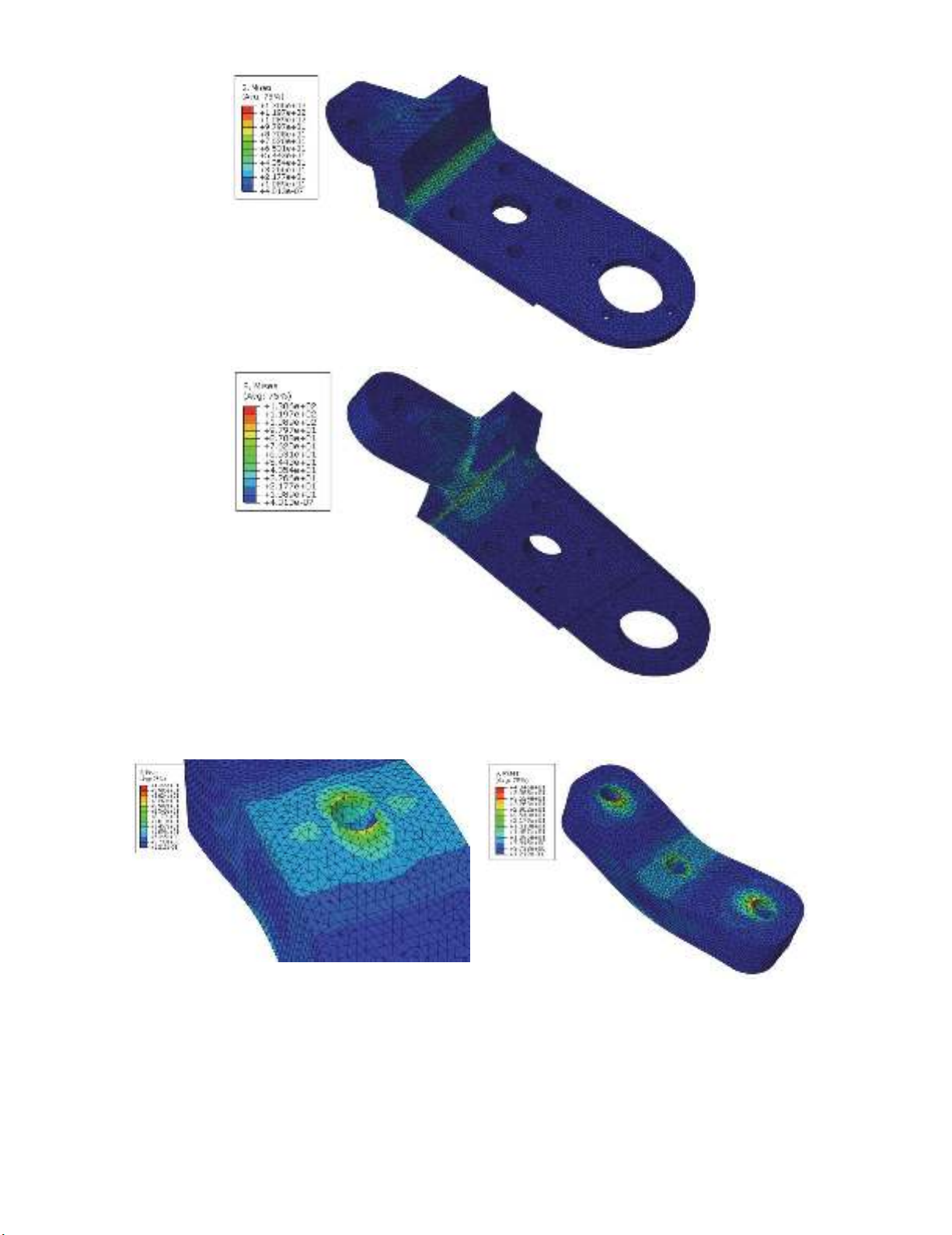
modelled and analyzed using the ABAQUS software. The Maximum Distortion Energy Theory of
Failure was chosen as the criteria for part performance evaluation. Comparing the results with 7075-
T651 Aluminum limits, shows that the plates could withstand the working conditions. Fig. shows the
stress distribution of the motor plate.
The plate which is connected to the ball screw support plate, was assumed to be fixed at the contact
surface and a load of 1050 N was applied to the motor plate pin (which is connected to orthosis frame).
The analysis of the end mount of the actuator is shown in Fig. 3. Two rods are fixed at the holes on the
opposite sides of the plate; in the simulation, the plate is fixed in those holes. The load of the actuator
is applied to the hole in the middle, which is where the actuator connection is screwed on.
244
Fig. 2. Motor plate von Mises stress distribution
Fig. 3. End mount von Mises stress contour
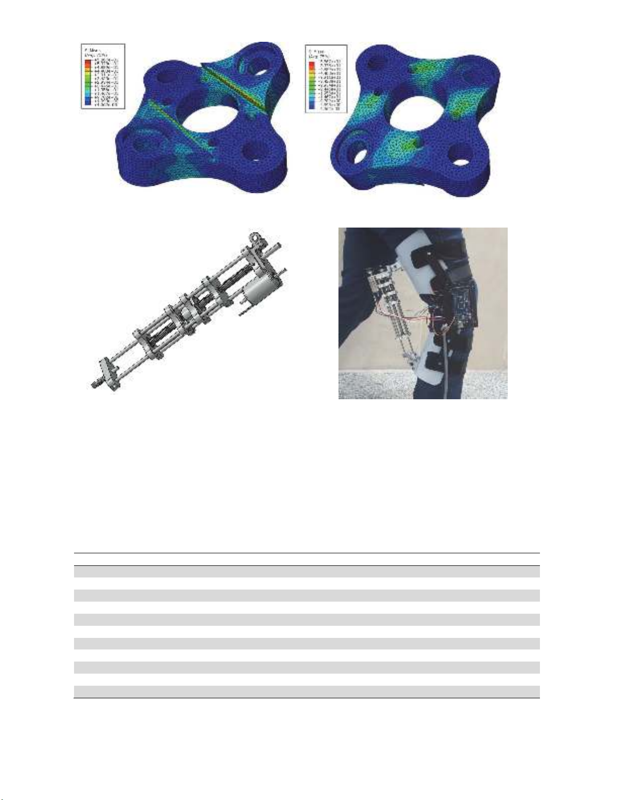
The nut plate is shown in Fig. 4. In the stress analysis, this plate was fixed in the nut contact surface
and tension/ compression load was applied in the springs' contact. Comparing the results of the finite
element stress analysis with the yield and fatigue strength for 7075-T651 aluminum (ASM International
Handbook 1990) shows that the actuator parts are safe under the loading conditions. The actuator model
is shown in Fig. 5.
A. Vadiati et al. / Engineering Solid Mechanics 6 (2018)
245
Fig. 4. Nut plate von Mises stress contour.
Fig. 5. CAD model of SEA actuator Fig. 6. Active knee orthosis prototype
mounted on healthy subject.
The most important task of the active orthosis is to create an auxiliary torque in the knee joint. This
action can be done rotationally or linearly. In this research, knee torque is produced by linear force and
with the help of a ball screw. In this plan we have avoided the direct connection of the electric motor
to reduce the length of the actuator, reduce the possibility of damage to the Motor and open the
designer's hand in changing the speed and torque input to the ball screw; the motor motion is carried
by belt and pulley. The Motor used in this research is EC-4pole 30. Finally, the series elastic actuator
has the features listed in Table 1. The active knee orthosis is shown in Fig. 6.
Table 1. Series elastic actuator specifications.
Parameters Values
Weight 710 g
Initial length 30 cm
Final length 45 cm
Diameter 6 cm
Max. linear speed 0.41 m/s
Continues force 510 N
Max. force 1200 N
Minimum resolvable force <10 N
Dynamic range 120
Operating voltage 18-48 Volts
Max. current 6A

![Phun Xăng Điện Tử: [Thêm từ khóa và thông tin giá trị để tối ưu SEO]](https://cdn.tailieu.vn/images/document/thumbnail/2013/20130609/nguyenduyvu89/135x160/4191370831173.jpg)
![Giáo trình động cơ phun xăng điện tử [chuẩn nhất]](https://cdn.tailieu.vn/images/document/thumbnail/2013/20130420/vanbanltlk11/135x160/1425722_159.jpg)

![Kiến thức cơ bản về điều khiển điện tử động cơ xăng [A-Z]](https://cdn.tailieu.vn/images/document/thumbnail/2011/20111124/gaunau123/135x160/dong_co_61__5197.jpg)


![Đề thi Động cơ đốt trong kết thúc học phần: Tổng hợp [năm]](https://cdn.tailieu.vn/images/document/thumbnail/2026/20260320/hoabattu2026/135x160/24841774320014.jpg)


