
* Corresponding author.
E-mail addresses: ghajar@kntu.ac.ir (R. Ghajar)
© 2013 Growing Science Ltd. All rights reserved.
doi: 10.5267/j.esm.2013.09.004
Engineering Solid Mechanics 1 (2013) 141-148
Contents lists available at GrowingScience
Engineering Solid Mechanics
homepage: www.GrowingScience.com/esm
Numerical analysis of hydrodynamic interaction between the linear waves of Caspian Sea and
Amirkabir semi-submersible drilling platform
Rahmatollah Ghajar* and Seyed Mohammad Navid Ghoreishi
Mechanical Properties Lab, Faculty of Mechanical Engineering, K.N. Toosi University of Technology, Tehran, Iran.
A R T I C L E I N F O A B S T R A C T
Article history:
Received March 20, 2013
Received in Revised form
September, 14, 2013
Accepted 18 September 2013
Available online
18
September
201
3
Semi
-
submersible drilling platforms are huge bulk structures for extracting the oil products
from great depth of seas. For such bulk structures, the Morrison’s equations are no longer valid
for determining the loads applied to the semi-submersible drilling platforms. The diffraction
theory should be used for evaluating the hydrodynamic interactions between the platform and
the sea waves. In this theory, the Laplace equation is solved by considering the boundary
conditions of the diffraction theory. In this paper, after a brief description of the diffraction
theory, the hydrodynamic interactions between the Iran’s Amirkabir semi-submersible drilling
platform and the regular linear waves of Caspian Sea is investigated numerically using
boundary element method in the ANSYS/AQWA software. The induced waves exciting forces
and moments with different wave heading angles are estimated for six degrees of freedom
relative to the waves frequencies using the diffraction theory. The performed hydrodynamic
analysis is also validated with the previous works performed for Spar platforms.
}}
© 201
3
Growing Science Ltd. All rights reserved.
Keywords:
Diffraction theory
Hydrodynamic analysis
Semi-submersible drilling platform
Regular waves
1. Introduction
Nowdays the discovery of the oil and gas resources in the seas has been focused to the great depths
and the use of fixed platforms (which are limited to depths of 360 to 450 m) is not applicable for
these situations. Hence, the use of new submersible and floating platforms such as tension leg
platforms (TLP), semi-submersible platforms, spar platforms and etc. which are suitable for great
depths is rapidly growing (Wilson, 2003, Gerwick, 2002). The first step for designing the semi-
submersible platforms is their hydrodynamic analysis and estimating the induced forces from the sea
waves to the platforms. In other words, estimating the critical wave is the key issue for design of
semi-submersible platforms. Since this type of platforms is among the huge offshore structures, it is
necessary to employ the diffraction theory for determining the applied waves to the platform and
analyzing its hydrodynamic response. A review of literature shows that Mendes et al. (2003)

142
investigated the forces induced by the sea waves to the offshore structures using numerical analyses.
They used Morrison’s equations for determining the interaction forces between the water and the
structure. Ran et al. (1996) analyzed the mooring system of spar platforms subjected to linear and
regular sea waves using Morrison’s equations. However, it is now widely accepted that for huge
offshore structures the use of Morrison’s equations may result significant errors in estimating the
induced forces and for such structures it is better to use the diffraction theory. Accordingly, Ketabdari
and Mirzaei Sefat (2011) recently studied the dynamic behavior of a Spar platform using finite
difference numerical method by employing the diffraction theory. They obtained the exciting forces
induced from the sea waves to the spar platform in six degrees of freedom. Liu et al. (2012) studied
wave diffraction and radiation by a submerged sphere in infinite water depth analytically. Teng and
Kato (1999, 2002), determined the applied forces to a floating cylinder induced by the interactions
between the second and third order regular linear waves and the cylinder using the diffraction theory
in the frequency domain and by analyzing a finite difference model. Also, using boundary element
method, Ray (2000) determined numerically the response amplitude operator, the applied forces and
moments in the frequency domain and for six degree of freedom for different models such as
cylinders and spheres. Mohseni Armak and Gharebaghi (2012) studied the effect of heave plates on
the hydrodynamic response of Iran’s Amirkabir semi-submersible drilling platform. They concluded
that adding the heave plates improve the hydrodynamic response of the platform especially its
vertical movement and rotating about the lateral axes. In this paper, the induced waves exciting forces
and moments with different wave heading angles are estimated from the regular and linear waves of
the Caspian Sea on the Amirkabir platform by employing the diffraction theory.
2. Induced forces from the sea waves on the platforms
The sea waves apply significant dynamic forces to the offshore and marine structures. Thus accurate
estimations of induced sea forces are very important parameters for designing such structures. The
waves in real situations are non-linear and their forces are variable with time but they are generally
assumed to be simple and harmonic. For small and slender structures, the wave parameters remain
nearly constant before and after impact to the structure because of the small size of structure relative
to the wave length. However, when the size of structure becomes larger, variations of wave
parameters are not negligible, and the structure affects the wave field and may introduce some
disturbances. Thus, diffraction of the wave is expected after passing from the huge offshore structures
and hence the influence of such effect for estimating the induced forces of waves should be taken into
account. For such situations the Morisson’s equation is not valid and in general when the diameter of
structure to the wave length is more than 0.2 (such that the case of Amirkabir semi-submersible
drilling platform) the diffraction theory should be used for analyzing the hydrodynamic response of
the structure. For huge platforms it is often assumed that the fluid is inviscid and incompressible, the
motion is irrational and periodic and hence the flow field can be depicted by a velocity potential
∅(,,). For such conditions the Laplace governing equation can be written as follows (Chakrabarti.
1987):
(1)
∇
∅
=
∂
∅
∂
+
∂
∅
∂
+
∂
∅
∂
=
0
where x, y ,z, are the Cartesian system coordinates and ∅ is the potential function of velocity. In the
diffraction theory the potential function of a linear wave can be divided to three parts namely: (i)
incident wave (∅), (ii) diffraction wave (∅) and (iii) radiation wave (∅) as:
(2)
∅
=
∅
+
∅
+
∅
3. Dynamic analysis
For dynamic analysis of the system, it is necessary first to obtain the added mass, damping and
stiffness coefficients and also the forces applied to the body for all of the degrees of freedom. These

R. Ghajar and S. M. Navid Ghoreishi / Engineering Solid Mechanics 1 (2013)
143
coefficients should then be replaced into Eq. (3) to study the dynamic response of the body (Mirzaye
Sefat & Ketabdary (2007)):
(3)
(
+
)
+
+
=
F
,
where m is the added mass coefficient, M is the mass of body, C and K are the damping and stiffness
coefficients, respectively and Fw is the applied external force. The mentioned coefficients have
different values in any free degrees of freedom. The applied loads are often determined in terms of
the amount of pressure applied to the body, which can be obtained from Bernoli’s equation as
follows:
(4)
(
)
+
∅
+
1
2
|
∇
∅
|
+
=
(
)
,
where P is the pressure, and g are the density of fluid and the gravity acceleration, respectively. C(t)
is an arbitrary value which can be assumed equal to zero. For assuming the waves as linear waves, the
pressure should be also considered as linear. This can be done by ignoring the hydrostatic term and
the second order dynamic effects of waves. Thus, the applied force can be determined from:
(5)
(
)
=
∫
∫
(
)
.
.
=
∫
∫
.
∅
.
.
,
In Eq. (5), n is the normal vector of the surface and if the potential function is written in terms of
incident, diffraction and radiation waves, one gets:
(6)
(
)
=
.
.
.
∅
+
∅
+
.
∅
.
Eq. (6) can be also rewritten as:
(7)
(
)
=
.
=
.
+
.
+
.
+
where,
is the amplitude of total force. Also, .
and .
are the amplitudes of Froude-Krylove
and diffraction loads and thus .
+
is the amplitude of the total force applied to the structure.
The load amplitudes of incident, diffraction and radiation waves can be also obtained from:
(8)
=
.
∅
.
=.∅
.
=
.
∅
.
4. Verification of numerical modeling for hydrodynamic analysis
Since the main objective of this paper is to analyze the hydrodynamic response of a real huge semi-
submersible platform (i.e. the Amirkabir platform) using numerical modeling, first it is necessary to
verify the used modeling process. Hence, before modeling and analyzing the Amirkabir platform, the
modeling process was verified using the previous similar works performed for Spar platforms (Ray,
2000; Ketabdari & Mirzaei Sefat, 2011). Ray (2000) used MOSES and WAMIT codes for modeling
of a Spar platform using boundary element method. Ketabdari and Mirzaei Sefat (2011) also analyzed
a platform numerically by means of a finite difference method. While the finite difference method
uses volumetric and three dimensional meshes (and hence a large number of elements may be used
for modeling a huge structure), only the surface of a structure is needed to be meshed in the boundary
element method. Consequently, this method is more suitable for numerical modeling of huge
144
structures such as offshore platforms. Thus, the boundary element method is employed for analyzing
the hydrodynamic response of the platform. Geometrical specifications of the modeled Spar platform
are listed in Table 1.
Table 1
Geometrical specifications of the modeled Spar platform.
Platform specification Value
Height 400 m
Diameter 40 m
Operation draught 200 m
Weight 256011 ton
Accordingly a Spar platform with the mentioned specifications in Table 1 is modeled in
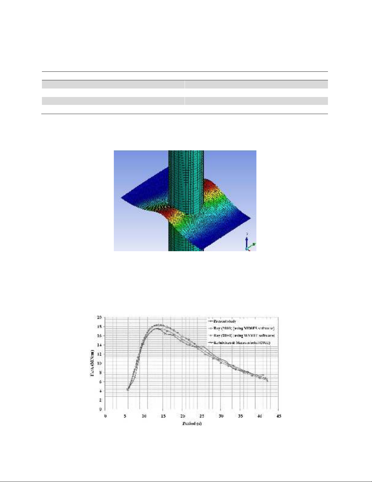
ANSYS/AQWA software and the induced forces from the sea waves are computed. Fig. 1, shows the
applied wave to the Spar platform which is modeled in ANSYS/AQWA.
Fig. 1. A typical wave applied to the Spar platform
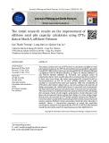
Fig. 2 compares the applied sea wave force in the x direction (i.e. surge direction) computed in this
research with the previous works. The good agreements that are seen between the numerical results of
this study with the results reported by Ray (2000) and Ketabdari and Mirzaei Sefat (2011) indicate
the accuracy and validity of the employed method of this research. Similar consistencies were also
obtained for the forces and moments in other degrees of freedoms.
Fig. 2. Comparison of wave exciting forces applied to a typical Spar platform in the surge direction

R. Ghajar and S. M. Navid Ghoreishi / Engineering Solid Mechanics 1 (2013)
145
5. Modeling of the Amirkabir semi-submersible drilling platform
The Amirkabir semi-submersible drilling platform which is designed and manufactured for discovery
and extraction of oil at depth of 1000 m of the Caspian Sea has the following main specifications
(Mohseni Armak & Gharebaghi, 2012):
Table 2. Specifications of the Amirkabir platform.
Diameter of columns
12.9 m
Diameter of brace 2 m
Longitudinal distance of columns
54.72 m
Transverse distance of columns 54.72 m
Height to lower deck 28.5 m
Operation draught
19.5 m
Height to upper deck 36.5 m
Breadth outside pontoon 73.4 m
Length of pontoon 80.56m
Breadth of pontoon 18.68 m
Height of pontoon
7.5 m
Total weight of platform 28621 ton
Environmental specifications of the Caspian Sea for a period of 100 years have also been reported by
Mohseni Armak & Gharebaghi (2012) as:
Table 3. Environmental characteristics of the Caspian Sea for period of 100 years (Mohseni Armak &
Gharabaghi, 2012)
Orientation relative to
north direction (degree)
Probability of
occurrence (%)
Height of nominal
wave (m) Period (s)
0 24 10.50 11.53
45 14 10.20 10.45
90 13 9.30 10.17
135 7 8.10 8.83
180 7 7.35 8.24
225 8 8.25 8.95
270 10 8.85 9.85
315
18
10.05
11.06
According to the data of Table 3, the most critical case i.e. the wave with zero degree relative to north
direction (with height of 10.5 m and period of 11.53 s) is chosen for applying the wave loads to the
Amirkabir platform. The occurrence probability of such a wave is more than the other types of waves
in the Caspian Sea. The density of the Caspian Sea water is considered as 1025 kg/m3. For
performing the hydrodynamic analysis it is necessary that the mass momentum inertias of the whole
platform about its gravity centroid to be known. The ABAQUS code was employed for determining
the required momentum inertias. The following properties was assumed for the platform made of
steel material: E = 200 GPa, =7860
⁄. Table 4, presents the determined mass momentum
inertias for the Amirkabir platform.
Table 4. Mass momentum inertias of the whole Amirkabir semi-submersible drilling platform about
its gravity centroid
I
zz
I
yy
I
xx
Mass momentum inertias
3.16×10
10
1.99×10
10
2.24×10
10
Value (Kg.m
2
)
Fig 3, shows the model of Amirkabir semi-submersible drilling platform created in ANSYS/AQWA
software.


![Đề cương bài giảng Bản đồ đại cương [mới nhất]](https://cdn.tailieu.vn/images/document/thumbnail/2026/20260323/hoatudang2026/135x160/81191774414215.jpg)
![Tài liệu giảng dạy Bản đồ và Hệ thống thông tin địa lý [chuẩn nhất]](https://cdn.tailieu.vn/images/document/thumbnail/2026/20260323/hoatudang2026/135x160/61501774414218.jpg)


