
* Corresponding author.
E-mail addresses: atma.yudha.prawira@gmail.com (A. Y. Prawira)
© 2017 Growing Science Ltd. All rights reserved.
doi: 10.5267/j.esm.2017.3.003
Engineering Solid Mechanics (2017) 93-102
Contents lists available at GrowingScience
Engineering Solid Mechanics
homepage: www.GrowingScience.com/esm
Size and configuration of mud motor drilling affects the optimum power outputs
Atma Yudha Prawiraa,b* and Etiko Puspo Rinic
aSchool of Mechanical Engineering, Balikpapan University, Indonesia
bSchool of Industrial Engineering, Mercu Buana University, Indonesia
cSchool of Electromechanical, Polytechnic Institute of Nuclear Technology, Indonesia
A R T I C L EI N F O A B S T R A C T
Article history:
Received 6 October, 2016
Accepted 3 March 2017
Available online
3 March 2017
The present invention provides a modular drilling assembly having a module for contactless
power and data transfer over a nonconductive gap between rotating and non-rotating members
of a steering module. The gap usually application data contains a non-conductive fluid, such
as drilling fluid, or oil for operating hydraulic devices in the down-hole tool. The down-hole
tool in one embodiment is a modular drilling assembly wherein a drive shaft is rotated by a
down-hole motor to rotate a drill bit attached to the bottom end of the drive shaft. Generally,
there are two main sections on mud motor which are bearing section and power section. The
power section generally includes a housing which houses a motor stator within which a motor
rotor is rotationally mounted. The power section converts hydraulic energy into rotational
energy by reverse application of the Moineau pump principle. The stator has a plurality of
helical lobes which define a corresponding number of helical cavities. The rotor has a plurality
of lobes which number one fewer than the stator lobes and which define a corresponding
plurality of helical cavities. Generally, the greater the number of lobes on the rotor and stator,
the greater the torque generated by the motor. Fewer lobes will generate less torque but will
permit the rotor to rotate at a higher speed. Based on torque and rotate speed, determine the
optimum power can be produced by power section configurations.
© 2017 Growin
g
Science Ltd. All ri
g
hts reserved.
Keywords:
Mud motor size
Power section
Number of lobes
Optimum power produced
1. Introduction
In general, the present invention provides a modular drilling assembly having a module for
contactless power and data transfer over a nonconductive gap between rotating and non-rotating
members of a steering module. The gap usually application data contains a non-conductive fluid, such
as drilling fluid, or oil for operating hydraulic devices in the down-hole tool. The down-hole tool in
one embodiment is a modular drilling assembly wherein a drive shaft is rotated by a down-hole motor
to rotate a drill bit attached to the bottom end of the drive shaft. A substantially non-rotating sleeve
around the drive shaft includes at least one electrically-operated device. The drilling assembly is
modular in that it includes at least one steering module at the bottom end of the drilling assembly that

94
has at least one steering device module that provides power to the force application member. A power
and data communication up-hole of the steering module provides power to the steering module and
data communication between the drilling assembly and the surface (Krueger et al., 2002). Also the
present invention relates to oil and gas well drilling and more particularly, to an improved mud motor
for drilling oil and gas wells and for drilling through obstructions, plugs and the like, in oil and gas
wells where in a high torque, low speed (i.e. low r.p.m.) motor is operated with a reciprocating valve
and piston arrangement that uses differential fluid pressure for power and a transmission that isolates
impact generated by the reciprocating valve and piston from the drill bit.In desirably low impact
situations, there is a need for a drill motor that operates with well drilling fluid or drilling mud. Such
“mud motors” have been commercially available for a number of years. All motors referred to as “mud
motors” are of multi-lobe positive displacement operating on the “Moineau” principal. One of the
limitations of these “mud motors” is their inability to operate in temperatures above about 250°
Fahrenheit. Another limitation of such “mud motors” is that they cannot operate for any length of time
on nitrogen or nitrified foam. They typically include a rotating member that is powered with the drilling
mud as it flows through an elongated tool body. Suppliers of such “mud motors” include Drillex,
Norton Christiansan, and Baker (Hipp, 2000).
To recover oil and gas from subsurface formations, well bores (also referred to as boreholes) are
drilled by rotating a drill bit attached at an end of a drill string. The drill string includes a drill pipe or
a coiled tubing (referred herein as the “tubing”) that has a drill bit at its down-hole end and a bottom
hole assembly (BHA) above the drill bit. The well-bore is drilled by rotating the drill bit by rotating the
tubing and/or by a mud motor disposed in the BHA. A drilling fluid commonly referred to as the “mud”
is supplied under pressure from a surface source into the tubing during drilling to wellbore. The drilling
fluid operates the mud motor (when used) and discharges at the drill bit bottom. The drilling fluid then
returns to the surface via the annular space (annulus) between the drill string and the wellbore wall or
inside. Fluid returning to the surface carries the rock bits (cuttings) produced by the drill bit as it
disintegrates the rock to drill the wellbore (Weirich et al., 2001).
Down-hole motors assemblies are well known in the drilling arts. Mud motors are one well known
type of down-hole motors. Mud motors are used to supplement drilling operation by turning fluid power
into mechanical torque to a drill bit. The mud is used to cool and lubricate the drill bit, to carry away
drilling debris and to provide a mud cake on the walls of the annulus to prevent the hole from sloughing
in upon itself or from caving in all together. Mud motors operate under very high pressure and high
torque operations and are known to fail in certain, predictable ways. The failure of mud motor is very
expensive, as the whole drill string must be pulled out of the bore hole in order to bring the mud motor
to the surface where it can be repaired and replaced. This is very time occur with prior art mud motors
include; seal failure resulting in drilling mud motor in the universal joint in the transmission section;
pressuring up, often called hydraulically locking, due to either fluid or gas being trapped within the
confines of the tool itself, and broken bearing mandrels and resulting mud invasion into the bearings
(Blair et al., 2004).
2. Literature Review
As mentioned earlier, the gap may contain a non-conductive fluid, such as drilling fluid or oil for
operating hydraulic devices in the down-hole tool. The down-hole tool, in one embodiment, is a drilling
assembly wherein a drive shaft is rotated by a down-hole motor to rotate the drill bit attached to the
bottom end of the drive shaft. A substantially non-rotating sleeve around the drive shaft includes a
plurality of independently-operated force application members, wherein each such member is adapted
to be moved radially between a retracted position and an extended position. The force application
members are operated to exert the force required to maintain and/or alter the drilling direction. In the
prefer system, a common or separate electrically-operated hydraulic unit provide energy (power) to the
force application members. An inductive coupling transfer device transfers electrical power and data
between the rotating and non-rotating members. An electronic control circuit or unit associated with
the rotating member controls the transfer of power and data between the rotating member and the non-
rotating member. An electrical control circuit or unit carried by the non-rotating member controls power

A. Y. Prawira and E. P. Rini / Engineering Solid Mechanics 5 (2017)
95
to the devices in the non-rotating member and also controls the transfer of data from sensors and devices
carried by the non-rotating member to the rotating member. In an alternative embodiment of the
invention, an inductive coupling device transfers power from the non-rotating housing to the rotating
drill shaft. The electrical power transferred to the rotating drill shaft is utilized to operate one or more
sensors in the drill bit and/or the bearing assembly. A control circuit near the drill bit controls transfer
of data from the sensors in the rotating member to the non-rotating housing. The inductive coupling
may also be provided in a separate module above the mud motor to transfer power from a non-rotating
section to the rotating member of the mud motor and the drill bit. The power transferred may be utilized
to operate devices and sensors in the rotating sections of the drilling assembly, such as the drill shaft
and the drill bit. Data is transferred from devices and sensors in the rotating section to the non-rotating
section via the same or a separate inductive coupling. Data in the various embodiments is preferably
transferred by frequency modulation. The drilling assembly is modular, in that relatively easily
connectable modules make up the drilling assembly. The modular drilling assembly includes at least a
steering module that carries the drill bit and includes a non-rotating sleeve that includes a plurality of
pluggable steering device modules. A power and data communication module up-hole of the steering
module provides power to the steering module and two-way data communication between the steering
module and the remaining drilling assembly. A subassembly containing multi propagation sensitivity
sensors and gamma ray sensors is disposed up-hole of the steering module. This subassembly may
include a memory module and a vibration module. A directional module containing sensors for
determining the drilling assembly direction is preferably disposed up-hole of the resistivity and gamma
sensor subassembly. Modular subassemblies make up portions of the steering assembly. The primary
electronics, secondary electronics inductive coupling transformers of the steering module are also
individual pluggable modules (Krueger et al., 2002).
A wellbore is formed in the earth with an elongated, non – rotating tubular drill stem which may
consist of a well casing or liner and including an expendable sub and reamer bit part connected to the
lower distal end of the drill stem. A retrievable drilling fluid operated motor and drive member
assembly are disposed in the drill stem. The motor and drive member include pressure responsive
mechanism for engagement with and disengagement from the reamer bit part to rotatable drive the
reamer bit part and a central bit part connected to the drive member without rotating the casing type
drill stem. The motor, drive member and central bit part may be retracted from the drill stem upon
completion of drilling operations without retrieving the expendable reamer bit part (Winfree, 1995). A
drill string typically comprises a tubular which is terminated at a lower end by a drill bit, and terminated
at an upper end at the surface of the earth by a “drilling rig” Which comprises draw works and other
apparatus used to control the drill string in advancing the borehole. The drilling rig also comprises
pumps that circulate drilling fluid or drilling “mud” downward through the tubular drill string. The
drilling mud exits through opening in the drill bit, and returns to the surface of the earth via the annulus
defined by the wall of the borehole and the outer surface of the drill string. A mud motor is often
disposed above the drill bit. Mud flowing through a rotor-stator element of the mud motor imparts
torque to the bit thereby rotating the bit and advancing the borehole. The circulating drilling mud
performs other functions that are known in the art. These functions including providing a means for
removing drill bit cutting from the borehole, controlling pressure Within the borehole, and cooling the
drill bit (Konschuh et al., 2011).
A down-hole drilling motor is provided with a bearing unit which supports the output shaft in such
an inclined position relative to the motor housing, that the central axis of the output shaft intersects the
longitudinal axis of the motor housing at a point of intersection located below the lower end of the
housing. Directional drilling of a borehole is carried out by actuating a drill bit by means of the down-
hole drilling motor, and simultaneously therewith rotating the drill string and consequently also the
motor housing-over periods that are preceded and succeeded by selected periods over which the drill
string is not rotated (Kamp, 1985). To obtain hydrocarbons such as oil and gas, boreholes or wellbores
are drilled by rotating a drill bit attached to the bottom of a drilling assembly (also referred to herein as
a “Bottom Hole Assembly” or (“BHA”). The drilling assembly is attached to the bottom of tubing,
which is usually either a jointed rigid pipe or a relatively flexible spoolable tubing commonly referred
to in the art as “coiled tubing.” The string comprising the tubing and the drilling assembly is usually

96
referred to as the “drill string.” When jointed pipe is utilized as the tubing, the drill bit is rotated by
rotating the jointed pipe from the surface and/or by a mud motor contained in the drilling assembly. In
the case of coiled tubing, the drill bit is rotated by the mud motor. During drilling, a drilling fluid (also
referred to as the “mud”) is supplied under pressure into the tubing. The drilling fluid passes through
the drilling assembly and then discharges at the drill bit bottom. The drilling fluid provides lubrication
to the drill bit and carries to the surface rock pieces disintegrated by the drill bit in drilling the wellbore.
The mud motor is rotated by the drilling fluid passing through the drilling assembly. A drive shaft
connected to the motor and the drill bit rotates the drill bit (Krueger et al., 2002).
It has been recognized that when a down-hole motor is rotating the bit on bottom while weight-on-
bit (WOB) is being applied thereto, a reactive torque in the counter clockwise direction is applied to
the housing of the motor, which includes the bent housing. The level of such counter torque is directly
proportional to the weight-on-bit, and has its maximum level at motor stall. Such reactive torque, and
the presence of a bend point in the bent housing, causes lateral forces to be applied to the bit which
tends to change the direction of the bore hole. However, to control the direction, there must be a way
to orient the bend point about the axis of the bore hole. As noted above, this is accomplished when
using a conventional drill pipe string by simply turning it at the surface. However, coiled tubing cannot
be manipulated in this manner. The present invention provides a means and method of orienting the
bent housing and its bend point down-hole, which enables a directional drilling tool string to be run on
coiled tubing (Eddison et a1., 1994). When drilling or coring holes in subsurface formations, it is often
desirable to be able to vary and control the direction of drilling, for example to direct the borehole
towards a desirable target or to control the direction horizontally within the payzone once the target has
been reached. It may also be desirable to correct for deviations from the desired direction when drilling
a straight hole, or to control the direction of the hole to avoid obstacles. (Russell et a1., 1993). The two-
basic means of drilling a borehole are rotary drilling, in which the drill bit is connected to a drill string
which is rotatable driven from the surface, and systems where the drill bit is rotated by a down-hole
motor, either a turbine or a positive displacement motor. Hitherto, fully controllable directional drilling
has normally required the use of a down-hole motor, and there are a number of well-known methods
for controlling the drilling direction using such a system (Barr et al., 1996). When drilling oil and gas
wells for the exploration and production of hydrocarbons, it is very often necessary to deviate the well-
off vertical and in a particular direction. Such deviation may be required, for example, when drilling
from land to explore formations beneath the sea or below a lake, or in the case of oil and gas production
offshore, when drilling 20 or 30 wells from the same platform, each going in a different direction to
gain the widest coverage of the hydrocarbon bearing structure. The latter can result in wells being as
much as 3 to 4 miles apart at the point where they pass through the production zone (Noble, 1992).
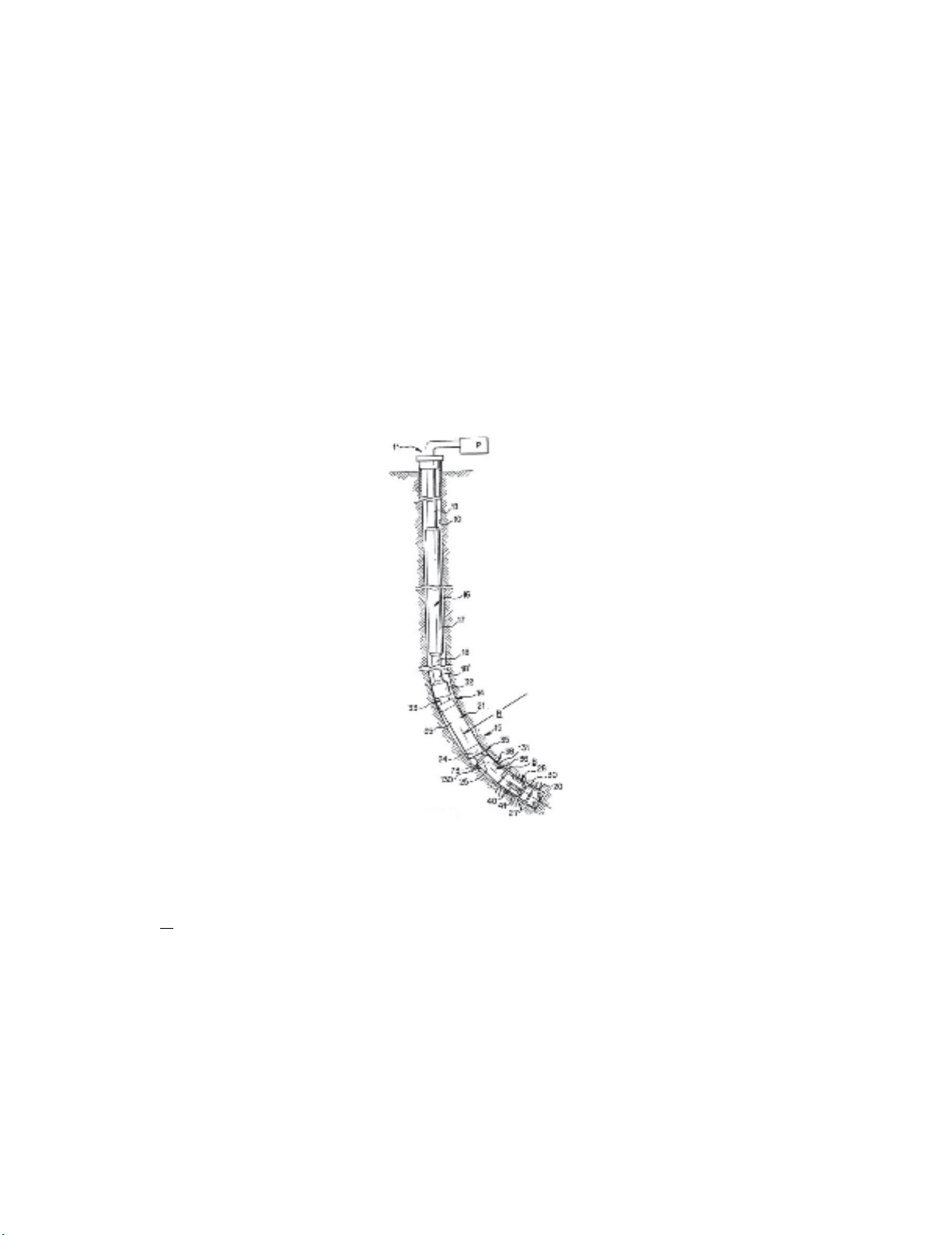
Referring initially to Fig. 1, a borehole 10 is shown extending downward, substantially vertically,
from a surface site 11 where a drilling rig (not shown) is located. At some depth below the surface,
depending on geology and other factors, the borehole 10 is shown being curved through a section 14
that eventually will bring its outer end to the horizontal. The radius of curvature R of the section 14 is
relatively short, and through use of the present invention can be in the order of about 60 feet for an
assembly that is used to drill a borehole having a diameter of 6 1/8". The curved section 14 is drilled
with an articulated drilling motor assembly 15 that is constructed in accordance with the present
invention. The motor assembly 15 is run on a drill string 16 that typically includes a length of heavy
drill collars 17 suspended below a length of drill pipe 18. A lower section of drill pipe 18' is used in the
curved section 14 of the borehole 10, since the drill collars usually are too stiff to negotiate the curve
and still function to apply weight. A drill bit 20 on the lower end of the motor assembly 15 can be either
a rolling cone or a diamond device. The power section 21 of the motor assembly 15 preferably is the
well-known Moineau-type design where a helical rotor rotates in a lobed stator in response to drilling
mud being pumped through it under pressure. The lower end of the rotor is coupled by a universal-joint
shown schematically at 24 to an intermediate drive shaft 73 whose lower end is coupled by another
universal joint 25 to the upper end of a hollow mandrel 27. The mandrel 27 is joumaled for rotation in
a bearing assembly 28, and the drill bit 20 is attached to a bit box 30 on the lower end of the mandrel
27 (Eddison, 1996).
A. Y. Prawira and E. P. Rini / Engineering Solid Mechanics 5 (2017)
97
A drilling motor includes a non-elastomeric stator and rotor which are dimensioned for negative or
Zero interference. The amount of negative interference between the rotor and the stator is determined
by the largest solid particle expected to pass through the motor. The negative interference or gap
between the rotor and the stator is preferably at least two times the greatest particle size. Stators are
made by machining or casting stainless steel and are fabricated in sections having lengths of 20 to 40
centimeters. The sections are indexed so that each section may be properly aligned with another. The
sections are aligned and welded together to form a motor stator of conventional length. Prior art Fig. 2
show details of the power section 18 of the down-hole motor. The power section 18 generally includes
a housing 22 which houses a motor stator 24 within which a motor rotor 26 is rotationally mounted.
The power section 18 converts hydraulic energy into rotational energy by reverse application of the
Moineau pump principle. The stator 24 has a plurality of helical lobes, 24a – 24e, which define a
corresponding number of helical cavities, 24a‘– 24e‘. The rotor 26 has a plurality of lobes, 26a – 26d,
which number one fewer than the stator lobes and which define a corresponding plurality of helical
cavities 26a‘– 26a". Generally, the greater the number of lobes on the rotor and stator, the greater the
torque generated by the motor. Fewer lobes will generate less torque but will permit the rotor to rotate
at a higher speed. (Pafitis et al., 2001).
Fig. 1. Drilling Motor Assembly
According to Han & Wang (2014), measuring method for motor torque is calculated by:
(1)
where:
T = Torque (Nm)
P = Power (Watt)
ω = Angular Velocity (Rad/s)


![Đề cương bài giảng Bản đồ đại cương [mới nhất]](https://cdn.tailieu.vn/images/document/thumbnail/2026/20260323/hoatudang2026/135x160/81191774414215.jpg)
![Tài liệu giảng dạy Bản đồ và Hệ thống thông tin địa lý [chuẩn nhất]](https://cdn.tailieu.vn/images/document/thumbnail/2026/20260323/hoatudang2026/135x160/61501774414218.jpg)


