
* Corresponding author.
E-mail addresses: shr492@mail.usask.ca (R.N. Shubhavardhan)
© 2018 by the authors; licensee Growing Science, Canada.
doi: 10.5267/j.esm.2017.12.001
Engineering Solid Mechanics (2018) 1-10
Contents lists available at GrowingScience
Engineering Solid Mechanics
homepage: www.GrowingScience.com/esm
Microstructure and fracture behavior of friction stir lap welding of dissimilar
metals
R.N. Shubhavardhana* and S. Surendranb
aDepartment of Mechanical Engineering, University of Saskatchewan, Saskatoon, Canada
bDepartment of Ocean Engineering, Indian Institute of Technology, Madras Chennai, India
A R T I C L EI N F O A B S T R A C T
Article history:
Received 26 August, 2017
Accepted 9 December 2017
Available online
9 December 2017
Friction Stir Welding (FSW) is a relatively new solid state joining technique which is used not
only for joining the aluminum and its alloys but also has potential for joining dissimilar
materials with very different physical and mechanical properties which are hard to weld using
conventional fusion welding processes. Tensile shear testing is used to determine the
Mechanical strength of friction stir lap (FSL) welds under static loading, fracture strength
(σLap) corresponding to the maximum load in a test over the sample width is widely used as
the strength value. During friction stir lap welding (FSLW) of dissimilar metals with large
differences in melting temperatures, a metallurgical bond is established through the formation
of interfacial intermetallic compounds. However, as these intermetallic compounds are
generally believed to be brittle with little ductility, they are generally considered to have
detrimental effect on fracture strength. The aim of the present research is to study how the
interface structure is affected by FSW parameters and how the formation of interface structure
affects fracture of Al-Steel and Al-Ti FSL welds.
© 2018 b
y
the authors; licensee Growin
g
Science, Canada.
Keywords:
Friction stir lap welding
Aluminum
Steel
Titanium
Intermetallics
Fracture strength
1. Introduction
Friction stir lap welding of dissimilar alloys such as Al-to Al, Al-to-steel, Al-to-Ti or Al-to-Cu is
also of enormous significance in many industries and many research activities have been done for
investigating such dissimilar weldments (Abdollah-Zadeh et al., 2008; Akbari et al., 2016; Aliha et al.,
2016, 2017; Aonuma & Nakata, 2011; Jiang & Kovacevic; 2004) In this paper, we focus on an example
of friction stir lap welding (FSLW) of one metallic alloy to another with considerably higher melting
temperature - FSLW of Al-steel and Al-Ti. It is well known that fusion welding of Al-to-steel and Al-
Ti is very challenging (Taban et al., 2010; Liedl et al., 2011). In FS welding of Al-steel and Al-Ti,
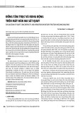
aided by frictional and deformation heat, metallurgical bond is established through diffusion and
2
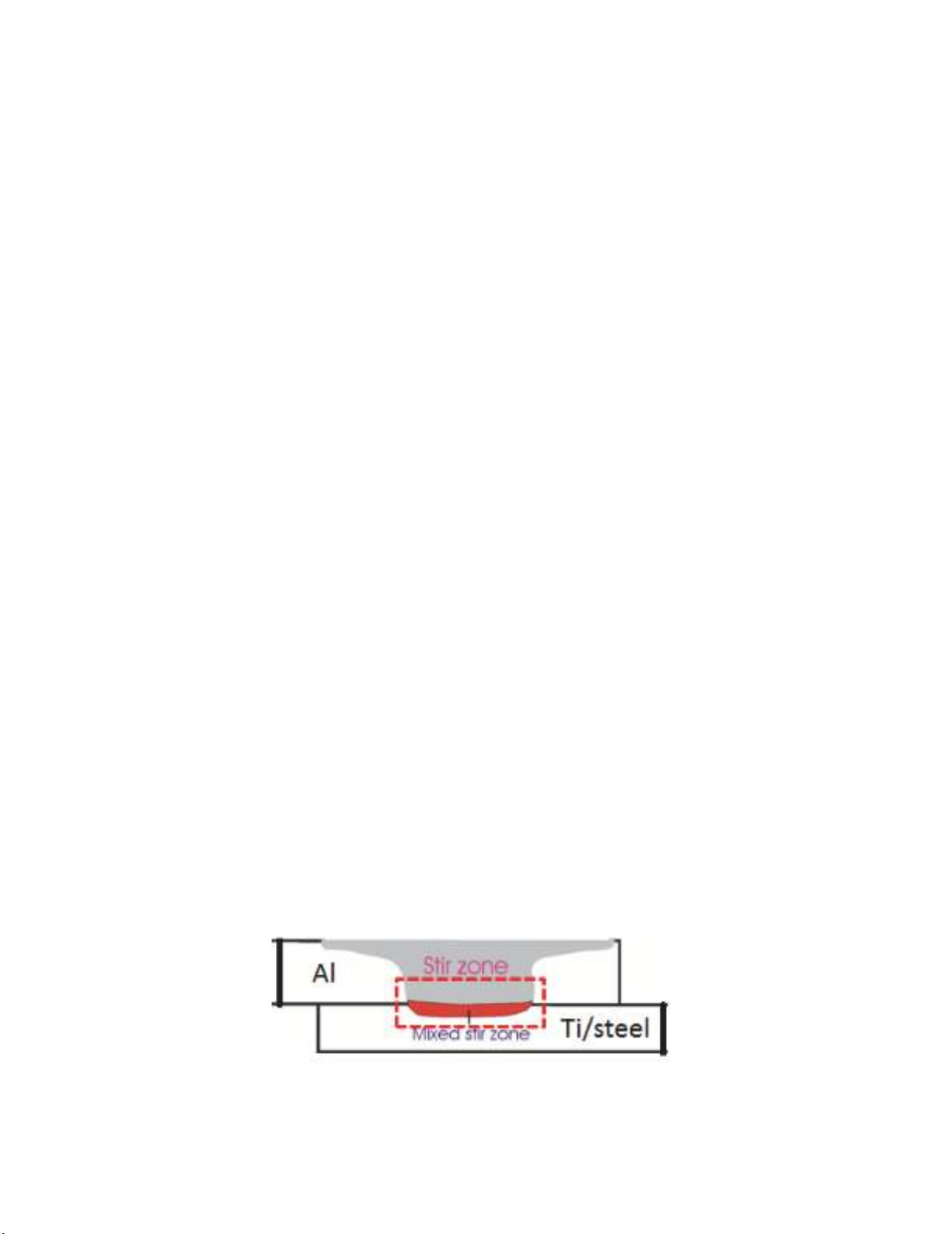
subsequent formation of interfacial intermetallic, as indicated in Fig. 1 for FSLW. A metallurgical bond
is a condition for a quality joint, although intermetallics are commonly viewed to affect joint strength
adversely (Elrefaey et al. 2005; Kimapong & Watanabe 2005). There have been many studies on FSLW
of Al-Steel (Coelho et al. 2008; Elrefaey et al. 2005; Chen & Nakata 2008; Chen et al. 2008; Movahedi
et al., 2011). Early investigation by Elrefaey et al. (2005) on Al-Steel FSLW clearly established that
the tool pin slightly (~0.1 mm) penetrating to steel is a condition for a metallurgical joint to be
established at the Al-Steel interface, resulting in a good joint strength. Although detailed quantification
was not done in their study, it was clear that the interface region of welds made with pin penetration is
a highly irregular structure of mix layers. Coelho et al. (2008) names the irregular interface region as
mixed stir zone. The thin layers, significantly less than 0.5 μm in thickness are laminated with
recrystallized fine grains of α-Fe in this mixed stir zone. Kimapong and Watanabe (2005a,b) made an
attempt to correlate the σLap to the thickness of the intermetallic layer, under the condition of pin
penetration. Their data shows that in general increasing intermetallic compound thickness reduces
σLap, however the meaning of the referred intermetallic thickness is unclear and misleading. In most
studies on FSLW of Al-Steel, tensile shear testing has been used for evaluating the joint strength.
Kimapong and Watanabe (2005a) reported σLap values, ranging from 280 N/mm to 559 N/mm for a
wide range of FSLW and pin penetrating conditions. However, the reason is unclear as to why some of
their welds displaying severe discontinuity with voids along the interface region, exhibited high values.
Al-Ti FSLW was conducted by Chen and Nakata (2009). Many void defects formed at the side of
titanium because of insufficient flow behavior of titanium during FSLW. However, when the pin did
not penetrate the titanium plate, the joint exhibited high σLap value of 469 N/mm. they also suggested
that AlTi3 intermetallic phase formed at the interface region, based on x-ray diffraction patterns
obtained from the fracture surfaces of tested samples. However, their results may not be accurate as no
visible intermetallic layer can be seen in SEM micrograph of interface region. Chen et al. (2012)
conducted detailed quantification was not completed in their study, it can be seen from their
micrographs that the interface region of welds is a highly irregular structure of mix layers. Review of
literature on other solid-state joining techniques such as diffusion bonding (Wilden & Bergmann, 2004)
and friction welding (Wilden & Bergmann, 2004; Fuji et al., 1997, 2001, 2004; Robertson & Schaffer,
2010) shows that TiAl3 intermetallic layer formed at the Al-Ti interfaces. However, the intermetallic
layer has been reported to be very thin (less than one micron) due to insufficient thermal energy for
intermetallics growth. On the other hand, formation of several micron thick TiAl3 intermetallic layers
has been commonly observed in fusion welding of Al-Ti welds (Vaidya et al., 2010; Chen et al., 2011).
That is because fusion welding techniques are all conducted at temperatures above the melting point of
aluminum, and thus higher peak temperature of welding together with presence of liquid aluminum
enhance the diffusion rate of Al-Ti atoms and thus faster growth of intermetallic layer. Therefore,
formation of TiAl3 phase at the Al-Ti interface is widely recognized to provide metallurgical bonding
in Al-Ti joints. In this paper FSLW of Al-to-steel and Al-Ti, to explain how interface microstructures
affect the fracturing process during tensile-shear testing and thus joint strength. A possible control
method for producing Al-to-steel and Al-Ti welds for a higher joint strength can then be suggested.
Fig.1. Schematic Illustration of interfacial intermetallics in mixed stir zone
R.N. Shubhavardhan and S. Surendran
/ Engineering Solid Mechanics 6 (2018)
3
2. Experimental procedure
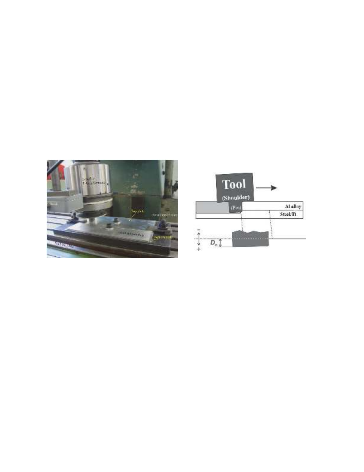
All FSLW experiments were conducted using a milling machine and thus the mode of FS was
displacement control. Schematic illustration of FSLW process has been provided in Fig. 2 shows an
actual FSLW experiment. A Lowstir
TM
device, which is also shown in Fig. 2, was used in each FSLW
experiment to monitor the down-force (Fz). This monitoring was necessary when a very precise
positioning was needed for the case of dissimilar metals friction stir lap welding. Monitoring of
temperature in the joining location was also conducted, by placing 0.2 mm K-type thermocouple wires
in the lapping location to be FSL welded. Work piece materials were A6060-T5 aluminum alloy plates
6 mm thick, Titanium and mild steel of 2 mm thick. Both top and bottom plates were 200 mm long and
100 mm wide. Tools were made using H13 tool steel and the left-hand threads of the pins were made
with a 1 mm pitch and a 0.6 mm actual depth. The diameter of the concave shoulder was 20 mm for
Al-to-steel/Ti FSLW and the pin outside diameter was 6 mm. A tool tilt angle (ϴ) of 3
o
was used. In
the present experiments, transverse speed (V) ranged from 20 to 540 mm/min and rotational speed (ω)
ranged from 600 to 1800 rpm. For the work reported here, the penetration depth Dp in Fig. 3 was varied
for FSLW of Al-to-steel/Ti.
Fig. 2. FSLW using a milling machine with a
Lowstir
TM
force measuring device
Fig. 3. Schematic illustration of tool positioning
during FSLW showing pin penetration depth
For microstructure observation, the welds were cross-sectioned, mounted and polished following
the normal metallographic procedure. Microstructure examination was conducted using a normal
optical microscope and a Hitachi SU-70 FE SEM with a Thermo Scientific NSS EDS/EBSD system.
Tensile-shear testing of FS lap welds has been the major method used for evaluating strength of FSL
welds in literature. This test method was adopted in this study. Test samples, 16 mm wide,
perpendicular to the welding direction were machined from the welded plates. Fig. 4 illustrates the
positioning of a sample together with supporting pieces. Samples were tested at a constant crosshead
displacement rate of 3 mm/min using a 50 kN Tinus Olsen tensile machine, with a 50-mm extensometer
attached. The strength of a lap sample cannot be expressed using the normal load/area, as the stress
distribution along the joint area during tensile-shear test is highly uneven. Instead, maximum failure
load in a test divided by the width of the sample, Fm/ws, is taken as strength.
3. Results and discussions
3.1a Al-Steel Microstructure analysis
Only two selected samples are shown here to illustrate the importance of interface microstructures
and based on this illustration a suggestion of FSLW control for maximum strength can then be made.
4
Fig.4 is the first example and a mixed stir zone (MSZ) commonly observed (e.g. Chen & Nakata (2009),
Kimapong & Watanabe (2005b)) is shown between the top Al plate and the bottom steel plate. The
area of MSZ largely corresponds to the area of the pin penetrated in to steel (in a 2D cross section) and
this zone is a mixture of Fe-Al intermetallic thin pieces embedded in the recrystallized α-Fe grains.
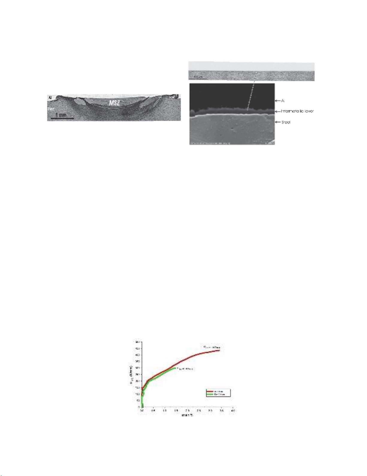
Fig. 4. Cross sectional view of an Al-to-steel weld made
with ω = 1,200 rpm, v = 40 mm/min and Dp ≈0.4 mm
displaying MSZ
Fig. 5. Cross sectional view of an Al-to-steel weld made
with ω = 1,200 rpm, v = 40 mm/min and Dp ≈ 0 mm
displaying no MSZ but an interface layer
With a MSZ, a metallurgical bond between Al and steel is established and thus a slight pin
penetration (a slight positive Dp value, referring to Fig. 3) is commonly believed to be the condition
for a good weld strength (e.g. Chen & Nakata (2009), Kimapong & Watanabe (2005b)). Naturally, a
MSZ cannot form and if Dp << 0. However, FS tool can be position controlled so that Dp ≈ 0. In this
case, although there can still be an absence of MSZ, a thin Fe-Al interface intermetallic layer can form,
metallurgically bonding the top and bottom plates together, as demonstrated by an example shown in
Fig. 5.
3.1b Al-Steel fracture strength
Two examples of tensile-tested curves are shown in Fig. 6 for the two different D
p
conditions. For
the penetrated sample, the amount of deformation before final fracture and thus fracture energy is not
low. The weld strength at 300 N/mm is significantly higher than that of Mg FSL welds (255 N/mm)
but is considerably lower than that of Al FSL welds (> 430 N/mm), for D
p
= 0. The weld strength at
300 N/mm is close to the values of ~ 315 N/mm which is the maximum value for a large group of
samples using a slight pin penetration (Chen & Nakata 2009). In this latter study, when a weld is free
of macro-defects the strength equivalent value is close to that maximum value, regardless of what the
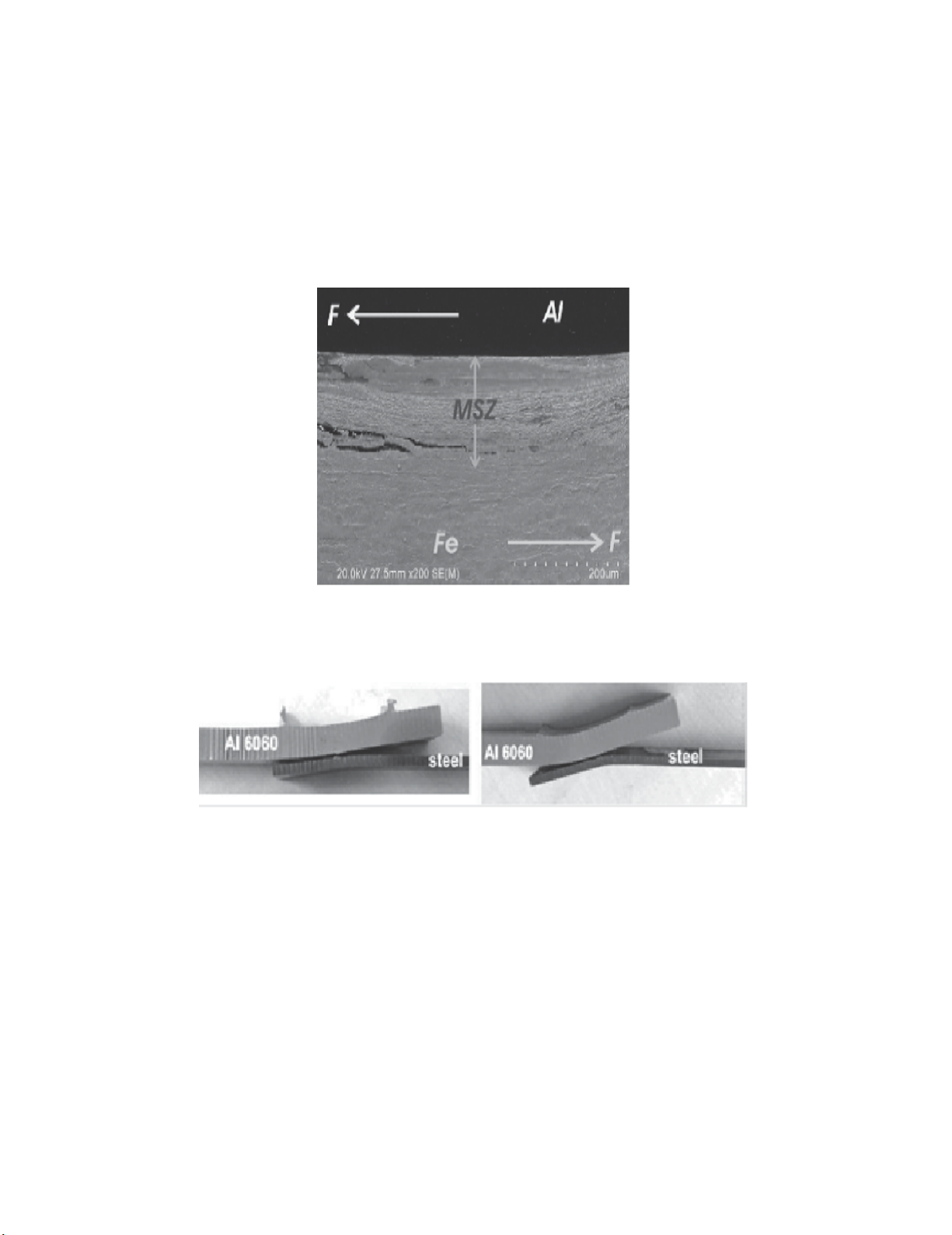
FS speed condition was. To understand this, an analysis was conducted on a specially tested sample in
the present work. As is clearly shown in Fig. 7, cracks propagated in MSZ, likely along the more brittle
Fe-Al intermetallic pieces and occasionally stopped by the tougher α-Fe grains. If this is the common
fracture feature and the required fracture strength will then be similar once a MSZ is established,
regardless of what the FS condition is so long as the weld is free of defects.
Fig. 6. Tensile-shear curves of two samples of welds made with ω= 1,200 rpm, v = 40 mm/min and
D
p
values as indicated
R.N. Shubhavardhan and S. Surendran/ Engineering Solid Mechanics 6 (2018)
5
When Dp ≈ 0 and an interface layer is established without MSZ, as shown in Fig. 6, fracture strength
(440 N/mm) is considerably higher than that for the sample with MSZ (300 N/mm). The amounts of
deformation and fracture energy as indicated by the curve suggest a considerably tougher weld made
by the zero Dp condition. These are clear by viewing the tested samples in Fig. 8. For the pin penetrated
sample (Dp ≈ 0.4 mm), the sample having been slightly bent is evident. On the other hand, for the zero
Dp sample, a large amount of local deformation and bending before the final fracture is clearly the
feature. The absence of MSZ in the zero Dp sample means a different fracture behavior. The large
amounts of deformation and fracture energy for this sample means that the thin interface layer is not
brittle under tensile-shear condition. From the present results, it can be suggested that careful
positioning control for Al-to-steel FSL welds is a mean for the optimal weld strength to be obtained.
Fig.7. SEM micrograph taken in MSZ region of a weld made with ω = 1,200 rpm, v = 40 mm/min and
Dp ≈ 0.4 mm and tested to 270 N/mm (~ 90 Fm/ws)
Fig. 8. Tensile-shear tested samples of welds made with ω = 1,200 rpm, v = 40 mm/min and (a) Dp
≈0.4 mm and (b) Dp ≈ 0 mm
Selected fractographs of tested samples are presented in Fig. 9. The cracks seen in Fig. 9a must be
thin as the thickness of the intermetallic layer and normal to the shear direction, thus contributing little
to the shearing process resulting in ductile fracture. A significant portion of the fracture surface as
shown in Fig 9b displayed brittle fracture feature. It is likely that cracking propagated along (parallel
to) the thin intermetallic layers in the penetrated laminate region during testing.
3.2a Al-Ti microstructure analysis
Microstructure corresponding to the sample 1 with Dp ≈ 0 pin penetration is shown in Fig. 10a
with low magnification SEM micrograph, however a very thin continuous intermetallic layer (with
average thickness of approximately ~ 300 nm) can be seen in the SEM micrograph of interfacial region
Fig. 10b. It should be noted that characterization of intermetallic layer was not possible in this study


![Thép cán kết cấu hàn: [Thông tin chi tiết/Báo giá/Hướng dẫn lựa chọn]](https://cdn.tailieu.vn/images/document/thumbnail/2020/20201014/maryland93/135x160/2381602661478.jpg)


![Giáo trình Cấu trúc dữ liệu và giải thuật - Trường CĐ Cơ điện Hà Nội [Mới nhất]](https://cdn.tailieu.vn/images/document/thumbnail/2026/20260323/lionelmessi01/135x160/58171774381670.jpg)


![Giáo trình Tiện nâng cao (Nghề Cắt gọt kim loại, Trình độ Cao đẳng) - Trường Cao đẳng Cơ điện Hà Nội [Mới nhất]](https://cdn.tailieu.vn/images/document/thumbnail/2026/20260323/lionelmessi01/135x160/48101774403543.jpg)


