Dao Vu Anh, Dan Bui Thi
MONITORING SPEED OF DC MOTOR
USING FUZZY PID CONTROLER VIA
WEB SERVER
Dao Vu Anh, Dan Bui Thi
Posts and Telecommunications Institute of Technology, Hanoi, Vietnam
Abstract: The use of PI, PD, and PID controllers to
control variable-speed motors is difficult to satisfy the
system's stability requirements. Therefore, adding fuzzy to
adjust PID parameters is a new direction for automatic
control systems to improve their quality. In this paper, we
propose a system using fuzzy PID controller,
STM32F103C8T6 microcontroller, ESP8266 wifi module
to monitor DC motor speed and some parameters to
evaluate the quality of the system through web server.
System simulation on Matlab-Simulink confirms the
effectiveness of this controller.
Keywords: PID, fuzzy PID; DC motor, web serve
I. INTRODUTION
A common problem in the field of control and
automation is to control the speed of the DC motor
precisely, stably, and respond quickly... because DC
motors are used in many industrial and household devices.
Proportional Integral (PI), Proportional Derivative (PD)
and Proportional Integral Derivative (PID) Controller are
some controllers widely used in industry. PID controller
has a long history in the field of control - automation. James
Watt introduced the first negative feedback system in 1769
and it was mathematically modeled by J. C. Maxwell in
1868 [1-3]. Later, Nicolas Minorsky gave a theoretical
analysis for the derivative of the error - its rate of change
[2]. Minorsky's contribution is the foundation of modern
PID controllers. Elmer Sperry deployed the first PID
controller in 1911 for the US Navy [3,4]. After many years,
the existing problems of the controller have been
troubleshooted. For example, the setting error of the
proportional controller is handled by the integral step, the
over-shooting is handled by the differential step. However,
designers still could not find the exact parameter for PID
controller until 1942, when Zieglers and Nichols
introduced method of parameter selection for PID
controller in different cases. The PID controller was widely
used in industry in the mid-1950s [5]. In the later stage, the
PID controller is integrated with more features such as self-
adjusting parameters [6,7], optimal PID [8], adaptive PID
[9], fuzzy PID [10-12]...
Even though, there have been many new control
methods discovered by reseachers, PID is favoritedly used
in controllers. The fact is, although PID often do not
achieve optimal performance, it can guarantee satisfactory
results for many technological processes. Due to its simple
structure, it is often considered the best solution based on
quality and cost.
Internet of Things (IoT) provides integration and
interaction between extensions, technologies or products
across multiple networks, focus on control schemes. Smart
IoT devices can play flexible connectors with changeable
architecture, which allowing for fast response and universal
access. In control systems, IoT is extensively utilized [13-
15], from automatic door systems, self-driving cars to
aircrafts. It allows communicatting real-time data without
human involvement.
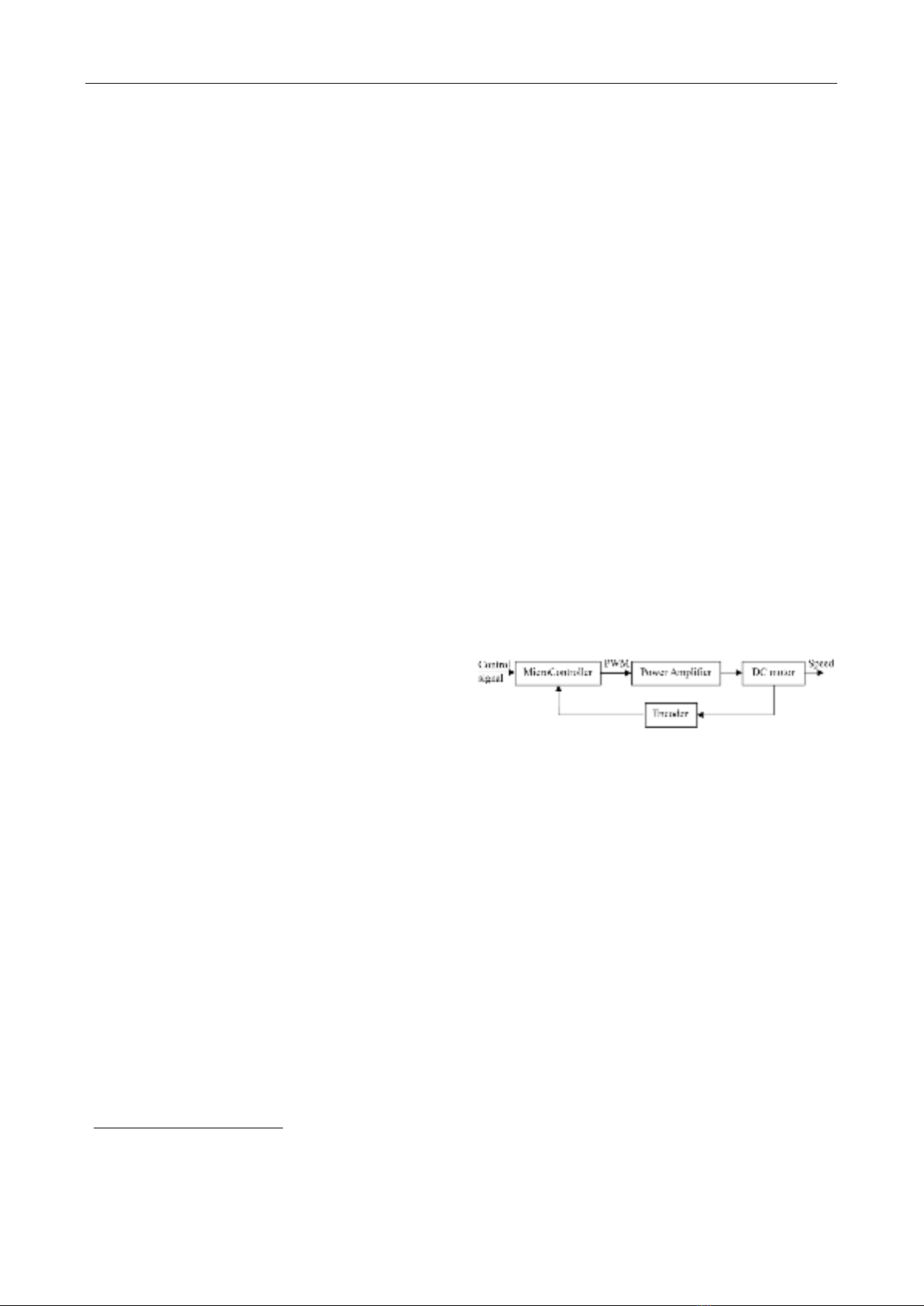
Fig. 1 Block diagram of speed monitor system of the DC
motor
The armature voltage variation method is commonly
used to control the speed of a DC motor. PWM technique
to control motor speed is selected by the authors. With this
method, the voltage supplied to the power amplifier
remains constant, but it’s output voltage to the DC motor
changes according to the control algorithm.
As shown in Fig. 1, the microcontroller plays the most
important role. It receives the control signal from the main
board, the feedback signal from the motor through the
encoder to calculate the necessary PWM value to output of
the power amplifier to control the motor to the desired
speed and position.
Power amplifier block provides the accurate voltage to
control the motor based on the processing and calculation
of the microcontroller. Depending on speed of the motor,
we must design this block suitably.
The encoder mounted on the motor provides
information about the it’s current state to the
microcontroller. The higher the encoder resolution, the
better the control quality. However, a high resolution
encoder also requires a higher processing power of the
microcontroller.
Contact author: Dao Vu Anh,
Email: daova@ptit.edu.vn
Manuscript received: 7/2023, revised: 8/2023, accepted: 9/2023.
No. 03 (CS.01) 2023
JOURNAL OF SCIENCE AND TECHNOLOGY ON INFORMATION AND COMMUNICATIONS 28

MONITORING SPEED OF DC MOTOR USING FUZZY PID CONTROLER VIA WEB SERVER
The paper proposes a system using fuzzy PID controller
for processes with diminishing response, this allows
determinning scaly, integral and differential coefficients
through fuzzy inference system and quality monitoring
system over the web. The main goal of this approach is to
improve system performance, i.e. reduce uptime,
overshoot, and response time. The goal of fuzzy logic is
improving system performance when the objects change.
The rest of this paper is arranged as follows. Section II
shows some theoretical bases as PID controller, fuzzy PID
controller, DC motor, microcontroller
STM32F103C8T6… System design steps are provided in
section III. The results of the proposed system are presented
and discussed in section IV. Finally, section 5 closed the
paper with some relevant conclutions.
II. THEORETICAL BASIS
A. PID controller
Fig. 2 is block diagram of control system using a typical
PID controller (this is also the most ideal form of a PID
controller). The control signal 𝑢(𝑡)has the equation:
( ) ( ) ( )
( ) ( )
0
0
1
t
p i d
t
CD
I
de
u t K e t K e t dt K dt
de
K e t e t dt T
T dt
= + +
= + +
(1)
Where
pC
KK=
is the proportional gain,
/
I c i
T K K=
is
the integral time, and
/
D d C
T K K=
is the derivative
time.
In terms of time, P depends on the current deviation, I
depends on the accumulation of past deviations, and D
predicts future deviations based on the current rate of
change. If the coefficient 𝐾𝑝 is big, the system is less
stable. Otherwise, the system is less sensitive or it slow
down the response. The integral component
(incorporating with proportional component) increases
the speed of the system to the setting point,
overshooting and eliminates the error. The differential
component is used to reduce the overshooting
generated by the integral component and improve the
stability of the controller. However, the derivation of a
signal amplifies noises, therefore, this component is
more sensitive with noises in the error, and it can make
the system unstable if noises and differential gain are
big enough. Therefore, choosing a suitable set of
parameters for the PID controller is essential.
Fig. 2 Block diagram system control using PID
Table. 1 lists the influence of controller parameters on
system quality. With the method Zieglers - Nichols [16], it
is not difficult to find the optimal set of parameters.
Table. 1 Effect of controller parameters on system quality
Parameter
Rising
Time
Over
adjusting
Excessive
time
Setting
error
𝐾𝑝
Decrease
Increase
Little
change
Decrease
𝐾𝑖
Decrease
Increase
Increase
Decrease
𝐾𝑑
Little
change
Decrease
Decrease
Unchange
B. Fuzzy PID controller
Fig. 3 Block diagram system control using Fuzzy PID
Block diagram system control using Fuzzy PID is
shown in Fig. 3. Fuzzy PID is based on rules, so it is
very stable. It consists of two inputs, the first input is
the error of the system (the difference between the
reference value and the actual value), the second one is
the change of the error (the derivation of the error). Its
three outputs are the parameters of the PID controller,
which is used to control the speed of the DC motor. The
precision of the PID controller and the flexibility of the
fuzzy controll are both in the fuzzy PID controller.
Comparison of the output of controllers is done on
Matlab-Simulink, shown in Fig. 4 and Table. 2.
Fig. 4 Response of the system when using traditional PID
controller, Sugeno fuzzy PID (type 1) and fuzzy PID using
Karnik-Mendel algorithm (type 2) [17]
Table. 2 Comparison of some parameters of the
controllers in Figure 3
Parameters
Type
Raise
time
Over
Adjusting
Transient
time
Error
PID
0.62412
11.234
4.5583
1.04
FLC type 1
1.4267
0
4.1023
1.1522
FLC type 2
1.8662
0
5.129
1.282
No. 03 (CS.01) 2023
JOURNAL OF SCIENCE AND TECHNOLOGY ON INFORMATION AND COMMUNICATIONS 29

Dao Vu Anh, Dan Bui Thi
C. DC motor
A DC motor uses direct current (DC) to produce
mechanical force. The stator of a DC motor is usually one
or more pairs of permanent magnets, or electromagnets. Its
rotor has a winding wire and it is connected to a DC power
source. Another important part is storage correction unit,
it is responsible for changing the direction of current when
the rotor turns continuously. Normally, for a DC motor,
the rotational speed is proportional to the voltage applied
to it, and the torque is proportional to the current. A DC
motor's speed can be controlled by a variable supply
voltage or by changing the strength of current in its field
windings. In the system that we design, we use DC geared
motor GA25 with some basic specifications:
- Voltage for motor operation: 3 - 12VDC
- Voltage for Encoder operation: 3.3VDC
- Gear ratio when passing through the reducer: 1:34
- Resolution: 44 pulses/rev.
- Motor diameter: 25mm.
- Shaft diameter: 4mm
- Torque: 1.88 kgf.cm
Fig. 5 DC geared motor GA25
D. The other components
1. Microcontroller STM32F103C8T6
Fig. 6 Microcontroller STM32F103C8T6
STM32F103C8T6 [18] (in Fig. 6) is a microcontroller
32-bit, belonging to the F1 family of the chip family
STM32. Its core is ARM COTEX M3 with a maximum
speed of 72Mhz; Flash memory 64 kbytes and SRAM 20
kbytes; operating voltage from 2.0 to 3.6V; 4 Timers 16-
bit and 2 watdog Timers… This series of high-density
mid-performance microcontrollers is suitable for a wide
range of applications such as motor control, medical and
handheld devices, PC and gaming peripherals, GPS
platforms, industrial applications…
2. Module wifi ESP8266
The ESP8266 [19] is a wifi transceiver module, which
is commonly used for applications needing data
connection and control via wifi. ESP8266 can use Arduino
IDE to program directly. In addition, its built-in wifi
2.4GHz makes it simpler and easier to use. Some key
parameters of the ESP8266 are 3.3V operating voltage;
built-in antenna; 802.11 wireless connection standard;
2.4 GHz wifi supporting WPA/WPA2 sercurity;
110-460800 bps baudrate; 4 Mb memory size.
3. Motor control module L298
Using H-bridge chip - L298 [20] makes DC motor easy
to control the speed and direction of rotation. In addition,
it is also used when PWM control when needed. The H-
bridge circuit of the L298 can operate at voltages from 5V
to 35V.
5. Software
Nowadays, there are many software helping study
algorithms and program for microcontrollers as well as
design web servers. The authors have selected software
that is easy to handle the requirements set out as
STMCubeIDE (Genuine software with many tools to
support in the process of writing programs for the
microcontroller STM32F103C8T6); Mathlab Simulink
(Simulate and research on Fuzzy-PID algorithms); Visual
Studio Code (Write programs for web servers); Arduino
(Write and load the ESP8266); Altium (Draw principle
Circuit and PCB Circuit).
III. SYSTEM DESIGN
A. Design Fuzzy PID controller
Controller Requirements:
+ The system has high quality with the ability to follow
the input signal.
+ The values of excessive time, setting error, over-
shooting are small. In practice, the POT (Percent of
OvershooT) of the system is usually less than 10%.
To design a fuzzy PID controller, at first, it is necessary
to determine the physical value domains of the controller's
input/output variables:
+ Determine the value domain of the error 𝑒:
The system uses a motor with a speed of 256 rpm, from
that the speed control range for the motor is R=[0;256] rpm.
We have:
𝑒 = 𝑅 − 𝐶 (2)
𝑒𝑚𝑖𝑛 = 𝑅𝑚𝑖𝑛 − 𝐶𝑚𝑎𝑥 = 0 − 256 = −256
𝑒𝑚𝑎𝑥 = 𝑅𝑚𝑎𝑥 − 𝐶𝑚𝑖𝑛 =256 − 0 = 256
The range of values of the error 𝑒[-256;256].
The range of error 𝑒 depends on the range of values
of the signal measured from the encoder during the
sampling time 𝑇
𝑠, so the range of the error values 𝑒 is in
the range [-30;30].
+ Determine the value domain of 𝑑𝑒/𝑑𝑡 :
01
s
ee
de
dt T
−
=
(3)
No. 03 (CS.01) 2023
JOURNAL OF SCIENCE AND TECHNOLOGY ON INFORMATION AND COMMUNICATIONS 30

MONITORING SPEED OF DC MOTOR USING FUZZY PID CONTROLER VIA WEB SERVER
where 𝑒0 is the current errror; 𝑒1 is the previous error
value; 𝑇
𝑠 is the sampling time (𝑇
𝑠 = 100ms).
We choose the range of values of 𝑑𝑒/𝑑𝑡 in the range [-
100;100].
+ Determine the value domain of PID controller
parameters:
We apply according to Mallesham-Rajani fuzzy
regulation [15], Assuming that three parameters 𝐾𝑝, 𝐾𝑖, 𝐾𝑑
are bounded:
𝐾𝑝
𝑚𝑖𝑛 ≤ 𝐾𝑝≤ 𝐾𝑝
𝑚𝑎𝑥, 𝐾𝑖
𝑚𝑖𝑛 ≤ 𝐾𝑖≤ 𝐾𝑖
𝑚𝑎𝑥 ; 𝐾𝑑
𝑚𝑖𝑛 ≤
𝐾𝑑≤ 𝐾𝑑
𝑚𝑎𝑥.
Fig. 7 Simulation of Fuzzy PID controller on Matlab-
Simulink
After many experiments, we determined the intervals of
these three parameters as follows:
𝐾𝑝=[0.005; 0.02]; 𝐾𝑖=[0.018; 0.03]; 𝐾𝑑=
[0.0000003; 0.0003]. These values are then normalized
to the interval [0,1]. Mamdani model for fuzzy controller
with MAX-MIN composition rule, average defuzzification
method (MOM). It has two inputs (𝑒; 𝑑𝑒/𝑑𝑡) and three
outputs ( 𝐾𝑝, 𝐾𝑖, 𝐾𝑑) simulated by Matlab software as
shown in Fig. 7.
Here, each input and output of the fuzzy set consists of
5 membership functions corresponding to 5 linguistic
variables:
Input: 𝑒= {NegBig, NegSmall, Zero, PosSmall, PosBig}
𝑑𝑒/𝑑𝑡 {DecFast, DecSlow, Maintain, IncSlow, Incfast}
Output: 𝐾𝑝, 𝐾𝑖, 𝐾𝑑 = {VSmall, Small, Medium, Large,
VLarge}.
Determine the physical value domain of the
input/output variables:
The determination of the range of values of physical and
linguistic variables is based on guesswork and experience
of designers. According to the above analysis, the group of
implementations selected:
𝑒 = [−30;30]; 𝑑𝑒/𝑑𝑡 =[−100;100]; 𝐾𝑝=
[0.005; 0.02]; 𝐾𝑖=[0.018; 0.03]; 𝐾𝑑=
[0.0000003; 0.0003]. The membership function of the
selected input and output variables has a triangular shape
as shown in Fig. 8. The fuzzy composition rule is designed
according to Table. 4.
(a)
(b)
(c)
(d)
(e)
Fig. 8 Membership function of input and output: (a) – ‘𝑒’,
(b) - 𝑑𝑒/𝑑𝑡, (c) - 𝐾𝑝, (d) - 𝐾𝑖, (e) - 𝐾𝑑
No. 03 (CS.01) 2023
JOURNAL OF SCIENCE AND TECHNOLOGY ON INFORMATION AND COMMUNICATIONS 31

Dao Vu Anh, Dan Bui Thi
Table. 4. Fuzzy composition rule
B. Hardware design
The hardware of the system is designed as shown in Fig.
1. Power supply for the circuit is a adapter with input AC
from 100V - to 240V, frequency 50/60Hz, output DC 12V
- 1A. Voltage 220 Vac is put through the adapter to lower
the voltage 12 Vdc for the motor.
C. Web server design
When any web Client (such as Web Browser) accesses,
web server will base on the requested accessing
information to process, and then respond to the requests.
The system uses HTTP protocol to exchange data
between Client and Server based on TCP/IP, uses three
languages such as HTML, Javascript and CSS to build and
develop the web. It includes the following steps:
Step 1: Structure the content of the web page such as
specifying paragraphs, titles, data tables, and embedding
real-time graphs in HTML.
Step 2: Add interactive functions to send requests to
receive data to the web and functions to receive data to plot
real-time graphs. Use the Javascript language with <script>
tags to embed programs in HTML.
Step 3: Handle the interface to make the web page more
beautiful. Use CSS to control the color of the text, the font,
the font size, the background image, or the background
color. Use a custom graphic <Style> tag for each object to
embed in HTML.
Fig.9 Web server design
IV. RESULTS AND DISCUSSION
Fig. 10 is the hardware that we design. Fig. 11 is the
control interface for monitoring and controlling the motor
via the web at 30 rpm. Here, the quality of the system is
evaluated through three quality criteria: overshooting,
transient time, and steady-state error. The control system
has the following characteristics:
Fig 10 Hardware of system
Fig.11 Motor control at speed 30 rpm
+ Control and stabilize the speed of the DC motor, the
transient time is relatively fast, the error and the
overshooting are small.
+ Control and monitoring interface via web server: data
is updated continuously over time.
As shown in Fig. 12, there is difference at the output of
DC motor for three cases such as not using a controller,
using a traditional PID controller and using a fuzzy PID
controller. We find that, when the system uses fuzzy
controller, the system has faster speed and smaller error. At
50 rpm, the system has zero overshoot.
Table. 5 is the system performance parameters (POT,
transient time, and steady-state error) at different DC motor
speed levels. Changing motor speed can be done flexibly
via web. We see that the above parameters are within the
allowable range for a control system.
Fig. 12. Output of DC motor for three cases such as not
using a controller, using a traditional PID controller and
using a fuzzy PID controller at speed 50 rpm.
Table. 5 System quality parameters at speed levels
No. 03 (CS.01) 2023
JOURNAL OF SCIENCE AND TECHNOLOGY ON INFORMATION AND COMMUNICATIONS 32


![Giáo trình Thực hành Truyền động điện Trường Đại học Bà Rịa - Vũng Tàu [Mới nhất]](https://cdn.tailieu.vn/images/document/thumbnail/2026/20260310/hoaphuong0906/135x160/11121773283865.jpg)
![Giáo trình Thực hành SCADA Trường Đại học Bà Rịa - Vũng Tàu [Mới nhất]](https://cdn.tailieu.vn/images/document/thumbnail/2026/20260310/hoaphuong0906/135x160/94061773283866.jpg)
![Tài liệu học tập La bàn từ [mô tả/định tính]](https://cdn.tailieu.vn/images/document/thumbnail/2026/20260310/hoaphuong0906/135x160/25191773287376.jpg)

![Tài liệu học tập Thiết kế hệ thống nhúng [mới nhất, đầy đủ]](https://cdn.tailieu.vn/images/document/thumbnail/2026/20260305/hoatulip2026/135x160/37051773135929.jpg)


![Giáo trình Điều khiển khí nén thuỷ lực Phần 2: [Mô tả/Chủ đề cụ thể của phần 2]](https://cdn.tailieu.vn/images/document/thumbnail/2026/20260302/camtucau2026/135x160/11911772768225.jpg)
![Giáo trình Điều khiển khí nén thuỷ lực Phần 1: [Mô tả/Định tính thêm nếu cần]](https://cdn.tailieu.vn/images/document/thumbnail/2026/20260302/camtucau2026/135x160/51511772768225.jpg)
![Giáo trình Điều khiển số Phần 2: [Thêm từ khóa mô tả nội dung chương trình]](https://cdn.tailieu.vn/images/document/thumbnail/2026/20260302/camtucau2026/135x160/37201772766913.jpg)
