
See discussions, stats, and author profiles for this publication at: https://www.researchgate.net/publication/260868676
Optimal design of high damping force engine mount featuring MR valve
structure with both annular and radial flow paths
ArticleinSmart Materials and Structures · October 2013
DOI: 10.1088/0964-1726/22/11/115024
CITATIONS
54
READS
751
4 authors, including:
Hung quoc Nguyen
Vietnamese-German University
182 PUBLICATIONS3,325 CITATIONS
SEE PROFILE
S. B. Choi
SUNY Korea
867 PUBLICATIONS16,918 CITATIONS
SEE PROFILE
Yuan-Shin Lee
North Carolina State University
219 PUBLICATIONS6,601 CITATIONS
SEE PROFILE
All content following this page was uploaded by Hung quoc Nguyen on 16 July 2014.
The user has requested enhancement of the downloaded file.

This content has been downloaded from IOPscience. Please scroll down to see the full text.
Download details:
IP Address: 165.246.74.129
This content was downloaded on 31/12/2013 at 09:07
Please note that terms and conditions apply.
Optimal design of high damping force engine mount featuring MR valve structure with both
annular and radial flow paths
View the table of contents for this issue, or go to the journal homepage for more
2013 Smart Mater. Struct. 22 115024
(http://iopscience.iop.org/0964-1726/22/11/115024)
Home Search Collections Journals About Contact us My IOPscience

IOP PUBLISHING SMART MATERIALS AND STRUCTURES
Smart Mater. Struct. 22 (2013) 115024 (10pp) doi:10.1088/0964-1726/22/11/115024
Optimal design of high damping force
engine mount featuring MR valve
structure with both annular and radial
flow paths
Q H Nguyen1, S B Choi2,4, Y S Lee3and M S Han3
1Department of Mechanical Engineering, Ho Chi Minh University of Industry, Ho Chi Minh City,
Vietnam
2Smart Structures and Systems Laboratory, Department of Mechanical Engineering, Inha University,
Incheon 402-751, Korea
3Faculty of Mechanical and Automotive Engineering, Keimyung University, Daegu 704-751, Korea
E-mail: seungbok@inha.ac.kr
Received 19 June 2013, in final form 10 September 2013
Published 17 October 2013
Online at stacks.iop.org/SMS/22/115024
Abstract
This paper focuses on the optimal design of a compact and high damping force engine mount
featuring magnetorheological fluid (MRF). In the mount, a MR valve structure with both
annular and radial flows is employed to generate a high damping force. First, the configuration
and working principle of the proposed MR mount is introduced. The MRF flows in the mount
are then analyzed and the governing equations of the MR mount are derived based on the
Bingham plastic behavior of the MRF. An optimal design of the MR mount is then performed
to find the optimal structure of the MR valve to generate a maximum damping force with
certain design constraints. In addition, the gap size of MRF ducts is empirically chosen
considering the ‘lockup’ problem of the mount at high frequency. Performance of the
optimized MR mount is then evaluated based on finite element analysis and discussions on
performance results of the optimized MR mount are given. The effectiveness of the proposed
MR engine mount is demonstrated via computer simulation by presenting damping force and
power consumption.
(Some figures may appear in colour only in the online journal)
1. Introduction
It is well known that engine mounts are extremely important
vehicle parts that stabilize and align a vehicle engine inside
the engine compartment. The engine mounts are also used to
suppress vibration from the vehicle engine being transferred
to the vehicle chassis to improve ride comfort performance
of the vehicle. Many types of engine mounts have been
developed and reported in the literature, and some of them
are now commercialized. Essentially, based on the amount
of external power required, engine mounts are classified
4www.ssslab.com.
into three types: the passive, the active and the semi-active.
The rubber mount is one of the most commonly used
passive mounts and has been widely used since the 1930s
because of its compactness, cost-effectiveness and its quality
of being maintenance-free. The rubber mount, a typical
passive engine mount which has low damping, shows efficient
vibration isolation performance in high frequency excitation.
But it cannot have a favorable performance at the resonant
frequency range—low frequency [1]. In order to compensate
for these limitations, various types of hydraulic mounts have
been developed and commercialized for several applications
including vehicles [2–8]. Briefly, the hydraulic mount is a type
10964-1726/13/115024+10$33.00 c
2013 IOP Publishing Ltd Printed in the UK & the USA

Smart Mater. Struct. 22 (2013) 115024 Q H Nguyen et al
of elastomeric mount with fluid traveling through the inertia
track between two compliant rubber chambers. The inertia
track imparts a frequency-dependent stiffness and damping
behavior to a hydraulic mount. At low frequencies, the mass
of fluid in the inertia track offers little resistance to motion
of the stiffer rubber element, and the mount stiffness is
primarily defined by the shear stiffness of the rubber. At a
characteristic frequency, the fluid in the inertia track moves
in resonance with the rubber element and the mount displays
a minimum in dynamic stiffness, known as the low-stiffness
notch. The phase angle, which is a measure of the phase
difference between the input and transmitted vibration, and
therefore also a measure of the damping behavior, reaches a
maximum near the notch frequency as well. This combination
of low dynamic stiffness and high damping is ideal for
damping in large motions. Above the notch frequency, the
fluid motion in the inertia track first opposes the rubber motion
and then becomes essentially static, causing an increase
and then a stabilization of the stiffness at a higher value
determined primarily by the bulge stiffness of the rubber [9].
For best noise/vibration isolation at high frequencies and low
amplitudes a softer mount is preferred. Therefore, hydraulic
mounts with an amplitude-sensitive decoupler are employed.
Although incorporating a decoupler, the hydraulic mounts still
have high dynamic stiffness at high frequency which results
in worse vibration isolation efficiency in the high frequency
domain. In addition, the notch frequency and stiffness of a
passive mount are fixed by its design and cannot respond to
changing conditions.
In order to improve the performance of passive engine
mounts, the active mount has been introduced and commer-
cialized. There have been different types of active mounts
reported in the literature such as the electromagnetic mount
developed by Muller et al [10], the hydraulic/pneumatic
mount proposed by Hodgson [11] and the active en-
gine mount featuring a piezoelectric actuator [12,13].
Generally, with an additional active force introduced as a
part of the active mount, the mount system can be controlled
using different algorithms to make it more responsive to
sophisticated sources of disturbance. Although the active
system can provide high control performance in a wide
frequency range, it is not widely utilized due to its
complex structure, large power requirement, and high cost
of manufacture and operation. A semi-active configuration
addresses these limitations by effectively integrating a tuning
control scheme with tunable passive devices. For this, the
active force generators in the active mount system are replaced
by modulated variable compartments such as variable-rate
valve and variable stiffness material. These semi-active
systems benefit from the advantages of active systems
combined with the reliability of the passive systems. If the
control system fails, the semi-active isolator can still work
in the passive mode. In addition, the power consumption
of these systems is very low, while they can change their
characteristics to make different levels of resisting forces
according to a low power-commanding signal. With these
strong points, the semi-active vibration control systems have
received much attention for automotive application. Recently,
there have been several research works on semi-active mounts
using MRF [9,14–16].
It is well known that MRF is a type of smart
fluid in a carrier fluid, usually a type of oil. When
subjected to a magnetic field, the fluid rapidly and
greatly increases its apparent viscosity, to the point
of becoming a viscoplastic solid. With these advanced
characteristics, many MRF based devices and systems
have been developed and successfully applied in the
industrial field such as MR valves, MR shock absorbers
and dampers, engine mounts and clutch/brake systems.
Generally, MRF based devices can be operated under three
different fluid working modes: shear [17,18], flow [19,20],
and squeeze [21,22]. A combination of these modes to
produce more advanced MRF based devices have been studied
in several research works [23]. Most of MR mounts operate
based on flow working mode of MRF [14,15]. However,
a combination of flow mode and squeeze mode has been
used in some research works to improve the vibration control
range of MR mount [16]. Although there have been many
research works on MR mount employing flow mode, only the
annular MRF flow is employed in these research works, so
the damping force generated by the MR mounts are not very
high. In addition, the optimal design of MR valve structure of
the mounts was not considered in these works. Consequently,
the main contribution of this research work is to propose a
new configuration of MR mounts employing both annular
and radial flows of MRF to generate a high damping force.
In order to achieve this research goal, optimal design is
performed considering the high damping force as well as the
compactness and the dynamic range of the MR mount. The
effectiveness of the proposed optimal design is demonstrated
via computer simulation and the results are discussed.
2. The high damping MR mount
In this section, configuration of the proposed MR mount is
introduced. In addition, damping force and off-state force of
the mount is derived based on the Bingham plastic behavior
of the MRF. Figure 1shows the configuration of the proposed
MR mount in this study. As shown in the figure, a MR valve
structure with both annular and radial flows is employed to
create a high damping force. The MR valve structure separates
the mount into two parts: the upper and the lower part. The
upper part consists of a rubber element, an upper base which
is fastened to the valve body to support the rubber element
and the top plate with a bolt in order to fasten the mount to
the engine. The hollow structure of the rubber element forms
the upper chamber of MRF above the valve structure. The
lower part consists of the mount body, the supporter on which
the core of the MR valve structure is placed and the rubber
diaphragm. The rubber diaphragm is placed right below the
valve structure to form the lower chamber. The MR valve
structure essentially consists of the valve body, the separating
ring, the upper and lower plates, the middle core and the
pins. The upper plate, the lower plate and the middle core are
all fixed together by the fastening bolt. The pins are placed
between the plates and the middle core to form radial flow
2
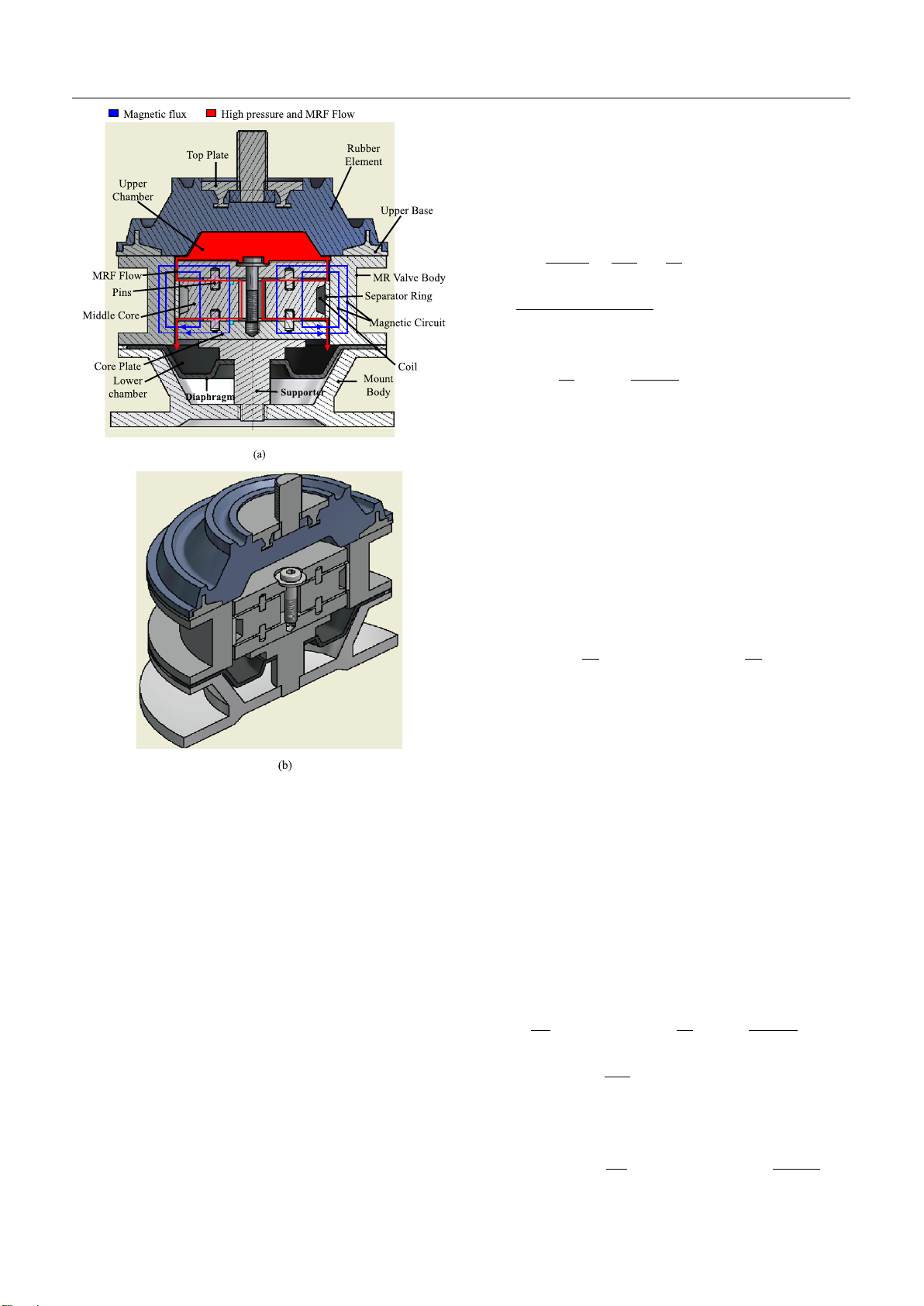
Smart Mater. Struct. 22 (2013) 115024 Q H Nguyen et al
Figure 1. Configuration of the proposed MR mount.
(a) 2D-configuration and (b) 3D CAD model.
paths of the valve. A nonmagnetic ring is placed between the
middle core and the MR valve body functioning as a magnetic
separator to prevent magnetic flux going from the middle core
to the valve body and also to force the MRF flows from
the upper chamber to the lower chamber through the radial
paths. When a high damping force is required, a current is
applied to the coil of the valve and a magnetic circuit going
across the MRF paths is generated. The generated magnetic
circuit causes an increase of yield stress and viscosity of the
MRF in both the annular and radial paths. By controlling the
applied current, the induced damping force of the mount can
be controlled.
The difference between the pressure in the upper chamber
(P1)and the pressure in the lower chamber (P2) can be
calculated by
P1−P2=1PI+1Pη+1PMR (1)
where 1PIis the pressure drop due to inertia of the MRF flow,
1PI=IeqQi, here Ieq is the equivalent inertance and Qiis
the average flow rate of the MRF flow in the mount. 1Pηis
the pressure drop of the MRF flow due to MRF viscosity and
1PMR is the pressure drop due to yield stress of MRF. By
assuming Bingham plastic behavior of MRF, 1Pηand 1PMR
can be approximately calculated by [24]
1Pη=12ηLp
πt3
gaRd
+η
πt3
gr
lnRo
Ri
+ηLc
π(Ri−Rb)3(Ri+Rb)Qi
=RηQi(2)
1Py=2Ca
Lp
tga
τya +Cr
Ro−Ri
tgr
τyr.(3)
In the above, ηis the post-yield viscosity of MRF, τya and τyr
are yield stress of MRF in the annular and the radial flow paths
respectively, Roand Riare respectively the outer and inner
radius of the valve core, Rbis the radius of the fastening bolt,
Lpand Lcare respectively the thickness of the core plates and
the middle core, tga and tgr are respectively the gap size of the
annular and the radial MR flow paths, Rdis the MR annular
duct radius Rd=Ro+tga/2,Rηis the viscous resistance of
the MRF flow, and Caand Crare coefficients which depend
on flow velocity profile and often has a value range from 2.0
to 3.0.
The pressure in the lower chamber can be estimated by
˙
P2=Qi
C2
or P2=Vi
C2
,(4)
where C2is the compliance of the lower chamber, and Viis
the volume of MRF from the upper to the lower chamber.
The MRF flow rate Qiis related to the pressure in the upper
chamber P1and the displacement of the top plate zby the
following equation of volume conservation:
˙
P1C1=Aef˙z−Qi,(5)
where Aef is the effective area of the upper chamber, and
C1is the compliance of the upper chamber. It is noted that
the rubber element of the mount is very stiff and hence the
upper chamber compliance C1is very small. In this study, by
neglecting the upper chamber compliance, the MRF flow rate
can be approximately determined by
Qi=Aef˙zor Vi=Aefz.(6)
From the above, the pressure in the upper chamber can be
calculated by
P1=Ieq
Aef
¨z+RηAef˙z+2Ca
Lp
tga
τya +Cr
Ro−Ri
tgr
τyr
×sgn(˙z)+Aefz
C2
.(7)
Now, the damping force of the MR mount can be determined
by
Fmr =P1Aeq =Ieq
Aeq
Aef
¨z+RηAefAeq˙z+Fy+AefAeqz
C2
,(8)
3


![Bài giảng Kỹ thuật điện - điện tử ô tô [chuẩn nhất]](https://cdn.tailieu.vn/images/document/thumbnail/2026/20260121/hoatrami2026/135x160/37681769069450.jpg)


![Câu hỏi ôn tập Truyền động điện [mới nhất]](https://cdn.tailieu.vn/images/document/thumbnail/2025/20250613/laphong0906/135x160/88301768293691.jpg)
![Giáo trình Kết cấu Động cơ đốt trong – Đoàn Duy Đồng (chủ biên) [Phần B]](https://cdn.tailieu.vn/images/document/thumbnail/2025/20251120/oursky02/135x160/71451768238417.jpg)
